EP0787604A2 - Vehicle tyre - Google Patents
Vehicle tyre Download PDFInfo
- Publication number
- EP0787604A2 EP0787604A2 EP97101181A EP97101181A EP0787604A2 EP 0787604 A2 EP0787604 A2 EP 0787604A2 EP 97101181 A EP97101181 A EP 97101181A EP 97101181 A EP97101181 A EP 97101181A EP 0787604 A2 EP0787604 A2 EP 0787604A2
- Authority
- EP
- European Patent Office
- Prior art keywords
- rubber
- tread
- polymer
- plastic
- vehicle tire
- Prior art date
- Legal status (The legal status is an assumption and is not a legal conclusion. Google has not performed a legal analysis and makes no representation as to the accuracy of the status listed.)
- Granted
Links
- 229920000642 polymer Polymers 0.000 claims abstract description 72
- 229920001971 elastomer Polymers 0.000 claims abstract description 65
- 239000005060 rubber Substances 0.000 claims abstract description 65
- 239000000203 mixture Substances 0.000 claims abstract description 28
- 239000004033 plastic Substances 0.000 claims abstract description 26
- 229920003023 plastic Polymers 0.000 claims abstract description 26
- 238000000034 method Methods 0.000 claims abstract description 10
- 239000007787 solid Substances 0.000 claims abstract description 8
- 238000004519 manufacturing process Methods 0.000 claims abstract description 7
- 238000005553 drilling Methods 0.000 claims abstract description 4
- 238000004073 vulcanization Methods 0.000 claims abstract 2
- VYPSYNLAJGMNEJ-UHFFFAOYSA-N Silicium dioxide Chemical compound O=[Si]=O VYPSYNLAJGMNEJ-UHFFFAOYSA-N 0.000 claims description 12
- 238000002347 injection Methods 0.000 claims description 12
- 239000007924 injection Substances 0.000 claims description 12
- 239000000377 silicon dioxide Substances 0.000 claims description 6
- 239000004071 soot Substances 0.000 claims description 5
- 239000007788 liquid Substances 0.000 claims description 3
- 230000002787 reinforcement Effects 0.000 claims description 3
- 239000004636 vulcanized rubber Substances 0.000 claims description 3
- 238000001125 extrusion Methods 0.000 claims description 2
- 229920000767 polyaniline Polymers 0.000 claims description 2
- 229920000128 polypyrrole Polymers 0.000 claims description 2
- 230000000149 penetrating effect Effects 0.000 abstract 1
- 229920001940 conductive polymer Polymers 0.000 description 15
- 239000000463 material Substances 0.000 description 13
- 239000005062 Polybutadiene Substances 0.000 description 5
- 229920002857 polybutadiene Polymers 0.000 description 5
- 244000043261 Hevea brasiliensis Species 0.000 description 4
- 229920003052 natural elastomer Polymers 0.000 description 4
- 229920001194 natural rubber Polymers 0.000 description 4
- 238000005096 rolling process Methods 0.000 description 3
- 238000000926 separation method Methods 0.000 description 3
- 235000021355 Stearic acid Nutrition 0.000 description 2
- NINIDFKCEFEMDL-UHFFFAOYSA-N Sulfur Chemical compound [S] NINIDFKCEFEMDL-UHFFFAOYSA-N 0.000 description 2
- XLOMVQKBTHCTTD-UHFFFAOYSA-N Zinc monoxide Chemical compound [Zn]=O XLOMVQKBTHCTTD-UHFFFAOYSA-N 0.000 description 2
- 230000003712 anti-aging effect Effects 0.000 description 2
- 239000011324 bead Substances 0.000 description 2
- 239000003795 chemical substances by application Substances 0.000 description 2
- 238000001816 cooling Methods 0.000 description 2
- 230000007547 defect Effects 0.000 description 2
- 239000003974 emollient agent Substances 0.000 description 2
- 238000004880 explosion Methods 0.000 description 2
- 239000002184 metal Substances 0.000 description 2
- 229910052751 metal Inorganic materials 0.000 description 2
- QIQXTHQIDYTFRH-UHFFFAOYSA-N octadecanoic acid Chemical compound CCCCCCCCCCCCCCCCCC(O)=O QIQXTHQIDYTFRH-UHFFFAOYSA-N 0.000 description 2
- OQCDKBAXFALNLD-UHFFFAOYSA-N octadecanoic acid Natural products CCCCCCCC(C)CCCCCCCCC(O)=O OQCDKBAXFALNLD-UHFFFAOYSA-N 0.000 description 2
- 239000000243 solution Substances 0.000 description 2
- 239000002904 solvent Substances 0.000 description 2
- 239000008117 stearic acid Substances 0.000 description 2
- 229920003048 styrene butadiene rubber Polymers 0.000 description 2
- 239000000126 substance Substances 0.000 description 2
- 229910052717 sulfur Inorganic materials 0.000 description 2
- 239000011593 sulfur Substances 0.000 description 2
- 235000014692 zinc oxide Nutrition 0.000 description 2
- 239000011787 zinc oxide Substances 0.000 description 2
- 125000000349 (Z)-3-carboxyprop-2-enoyl group Chemical group O=C([*])/C([H])=C([H])\C(O[H])=O 0.000 description 1
- 239000000654 additive Substances 0.000 description 1
- 238000010073 coating (rubber) Methods 0.000 description 1
- 150000001875 compounds Chemical class 0.000 description 1
- 238000004132 cross linking Methods 0.000 description 1
- 239000003431 cross linking reagent Substances 0.000 description 1
- 238000009795 derivation Methods 0.000 description 1
- 230000002349 favourable effect Effects 0.000 description 1
- 239000000945 filler Substances 0.000 description 1
- 230000009477 glass transition Effects 0.000 description 1
- 238000003780 insertion Methods 0.000 description 1
- 230000037431 insertion Effects 0.000 description 1
- 238000002156 mixing Methods 0.000 description 1
- 238000005457 optimization Methods 0.000 description 1
- 239000000049 pigment Substances 0.000 description 1
- 229920001195 polyisoprene Polymers 0.000 description 1
- 230000002028 premature Effects 0.000 description 1
- 238000003860 storage Methods 0.000 description 1
- VTHOKNTVYKTUPI-UHFFFAOYSA-N triethoxy-[3-(3-triethoxysilylpropyltetrasulfanyl)propyl]silane Chemical compound CCO[Si](OCC)(OCC)CCCSSSSCCC[Si](OCC)(OCC)OCC VTHOKNTVYKTUPI-UHFFFAOYSA-N 0.000 description 1
- 239000002699 waste material Substances 0.000 description 1
- 238000004804 winding Methods 0.000 description 1
Images


Classifications
-
- B—PERFORMING OPERATIONS; TRANSPORTING
- B60—VEHICLES IN GENERAL
- B60C—VEHICLE TYRES; TYRE INFLATION; TYRE CHANGING; CONNECTING VALVES TO INFLATABLE ELASTIC BODIES IN GENERAL; DEVICES OR ARRANGEMENTS RELATED TO TYRES
- B60C19/00—Tyre parts or constructions not otherwise provided for
- B60C19/08—Electric-charge-dissipating arrangements
-
- B—PERFORMING OPERATIONS; TRANSPORTING
- B29—WORKING OF PLASTICS; WORKING OF SUBSTANCES IN A PLASTIC STATE IN GENERAL
- B29D—PRODUCING PARTICULAR ARTICLES FROM PLASTICS OR FROM SUBSTANCES IN A PLASTIC STATE
- B29D30/00—Producing pneumatic or solid tyres or parts thereof
- B29D30/06—Pneumatic tyres or parts thereof (e.g. produced by casting, moulding, compression moulding, injection moulding, centrifugal casting)
- B29D30/52—Unvulcanised treads, e.g. on used tyres; Retreading
- B29D2030/526—Unvulcanised treads, e.g. on used tyres; Retreading the tread comprising means for discharging the electrostatic charge, e.g. conductive elements or portions having conductivity higher than the tread rubber
-
- B—PERFORMING OPERATIONS; TRANSPORTING
- B29—WORKING OF PLASTICS; WORKING OF SUBSTANCES IN A PLASTIC STATE IN GENERAL
- B29K—INDEXING SCHEME ASSOCIATED WITH SUBCLASSES B29B, B29C OR B29D, RELATING TO MOULDING MATERIALS OR TO MATERIALS FOR MOULDS, REINFORCEMENTS, FILLERS OR PREFORMED PARTS, e.g. INSERTS
- B29K2105/00—Condition, form or state of moulded material or of the material to be shaped
- B29K2105/0005—Condition, form or state of moulded material or of the material to be shaped containing compounding ingredients
- B29K2105/002—Agents changing electric characteristics
-
- B—PERFORMING OPERATIONS; TRANSPORTING
- B29—WORKING OF PLASTICS; WORKING OF SUBSTANCES IN A PLASTIC STATE IN GENERAL
- B29K—INDEXING SCHEME ASSOCIATED WITH SUBCLASSES B29B, B29C OR B29D, RELATING TO MOULDING MATERIALS OR TO MATERIALS FOR MOULDS, REINFORCEMENTS, FILLERS OR PREFORMED PARTS, e.g. INSERTS
- B29K2995/00—Properties of moulding materials, reinforcements, fillers, preformed parts or moulds
- B29K2995/0003—Properties of moulding materials, reinforcements, fillers, preformed parts or moulds having particular electrical or magnetic properties, e.g. piezoelectric
- B29K2995/0005—Conductive
Definitions
- the invention relates to a vehicle tire for mounting on an electrically conductive rim, which has a radially outer rubber layer, which has a specific electrical resistance greater than 10 exp 10 Ohm x cm.
- metal wires are known (DE-GM 19 92 389), which are introduced into the tire to discharge electrostatic charge and extend to the tread surface.
- wire structures are such. B. unsuitable for a belt tire, since the belt would be destroyed by rigid metal wires in the course of driving.
- the invention is based on the object of providing sufficient electrical conductivity in a tire of the type mentioned at the outset without sacrificing the driving properties or premature defects of the tire.
- the tread rubber layer in the area of the ground contact area of the tire has at least one substantially radially extending channel which is filled with a polymer plug made of rubber and / or plastic with a specific electrical resistance of less than 10 exp 8 ohm x cm, and that this polymer plug at least completely penetrates the electrically poorly conductive rubber layer.
- the polymer plug made of rubber and / or plastic is also intended to include mixtures of different rubber and / or plastics.
- the electrically conductive polymer plugs according to the invention are sufficient to discharge the electrostatic charge picked up during the driving operation of the tire to the road surface.
- the major part of the loaded loads is otherwise distributed over the entire chassis of the vehicle, so that a dangerous load is created and an explosion can occur when refueling.
- the discharge takes place via the rim, side wall, belt rubber, possibly rubber banding and the polymer plug according to the invention to the road surface. Since only one polymer plug, the diameter of which is between 1 and 10 mm, is required in the ground contact area, the area of the polymer plug is very small in relation to the circumference of the tire, which is in contact with the road surface. Therefore, rubber and / or plastics which do not have a positive influence on the properties (e.g.
- rolling resistance, wet skid behavior) of the tire can also be used as the polymer plug material, provided that their electrical resistance is less than 10 exp 8 ohm ⁇ cm.
- Another advantage of the relatively small diameter of the polymer plug, which extends through the non-conductive tread surface down to a highly conductive layer, is that a separation of the entire tread is not possible due to extensive mixture separating layers. Due to the geometric structure (small diameter) of the polymer plug, the polymer plug is prevented from crumbling out of the tread, since adhesion problems do not play a role. This does not limit the selection of mixtures that can be used for polymer plugs and treads.
- the polymer plugs according to the invention can be introduced both in solid rubber tires and in pneumatic tires. If it is a profiled tire, it is advantageous if the polymer plugs are located in areas of raised tread sections such as blocks or ribs, since these tread elements are in direct contact with the road surface and thus immediately dissipate any charges that occur. In principle, however, it is also possible to insert polymer plugs on non-raised profile sections (grooves).
- the polymer plug should have a specific electrical resistance of less than 10 exp 8 ohm x cm. Rubber and / or plastic containing soot is suitable for this. In particular, rubber containing soot is commonly used in tire manufacture (e.g., as a belt rubber), so that additional provision of material for the polymer plugs can be eliminated. But it is also advantageous if the polymer plugs are made of rubber or plastic, the conductive polymers such. B. contain polypyridines and / or polypyrroles and / or polyanilines. It is also possible to use these substances alone as polymer plug material. These substances have a particularly low specific electrical resistance, so that the diameter of the polymer plug can be kept even smaller so that the electrical charge can be sufficiently dissipated. This has the advantage that the contact area which the polymer plug has with the road surface is also very small, so that the driving properties of the tire are influenced even less by the polymer plug.
- the rubber and / or plastic of the polymer plug has a particularly low specific electrical resistance.
- the potential difference between the ground and the vehicle is particularly high in this case, which results in maximum dissipation.
- Specific electrical resistances of less than 100 ohm ⁇ cm have proven advantageous.
- the outer running rubber layer which surrounds the polymer plug, is a mixture containing silica.
- the optimal driving properties low rolling resistance, very good wet-slip behavior
- silica mixtures bring with them are exploited and, at the same time, the poor electrical conductivity is compensated for by the polymer plugs.
- previously known rubber mixtures which are suitable as an outer running rubber layer and have a specific electrical resistance greater than 10 exp 10 ohm ⁇ cm can be provided with polymer plugs.
- the tire according to the invention with polymer plugs can be produced by introducing polymer plugs made of vulcanized rubber and / or plastic with a specific electrical resistance of less than 10 exp 8 ohm ⁇ cm into the already vulcanized tires by means of an injection device, which extend at least through the part of the tread rubber layer , which has a specific electrical resistance greater than 10 exp 10 Ohm x cm.
- an injection device which extend at least through the part of the tread rubber layer , which has a specific electrical resistance greater than 10 exp 10 Ohm x cm.
- channels are essentially required in the radially inner direction, which z. B. generated by a drilling tool that forms part of the injection device and which extend at least through the entire poorly conductive rubber layer.
- the channels preferably extend to the layer in the tire interior which has the lowest electrical resistance in order to maximize charge dissipation achieve.
- the variant of introducing conductive polymer plugs into vulcanized tires has the advantage that conductive polymer plugs can be introduced specifically in the raised profile sections (blocks, ribs), so that an optimization of the number of polymer plugs is achieved.
- Another possibility for producing the tire according to the invention with conductive polymer plugs is to introduce conductive mixtures of unvulcanized rubber and / or plastic into the poorly conductive tread rubber layer of unvulcanized tires. This can be done by means of an injection device that contains the conductive polymer plug material in the form of unvulcanized rubber mixtures and / or plastic mixtures or solutions thereof. It is also possible to inject frozen polymer plug material.
- the advantage of introducing polymer plugs into an unvulcanized tire is that any material waste that arises is uncrosslinked and can therefore be reused. Furthermore, by vulcanizing / crosslinking the tread and the polymer plug together, optimum adhesion between these two components is achieved.
- EP 0 658 452 A1 in which additional extruders are generally required to extrude the conductive circulating tape, cheaper devices can be used when introducing the polymer plugs according to the invention.
- the polymer plugs made of unvulcanized rubber and / or plastic can also be introduced into pre-wound tire blanks.
- the insertion of polymer plugs in a tire or green tire is suitable both for solid rubber tires and for pneumatic tires.
- a pneumatic vehicle tire 1 with tread 2, belt 3, carcass 4, side wall 5 and a bead with bead cores 6, which is mounted on a rim 8.
- tread 2 are starting from the outer poorly conductive rubber layer radially inward channels, with a diameter of z. B. 3 mm, which are filled with conductive polymer plug 7.
- the polymer plugs 7 are at a maximum distance of 10 cm from one another, so that at least one polymer plug is always in contact with the road.
- the polymer plugs 7 are preferably introduced into the tread blocks of the tread 2 profile, not shown.
- the outer rubber layer has a specific electrical resistance of 10 exp 11 Ohm x cm (poorly conductive) and has the following composition: Table 1 Component: Concentration [pphr]: Natural rubber (NR) 10th Solvent styrene-butadiene rubber (SSBR) 60 Butadiene rubber (BR) 30th precipitated silica 70 Soot 10th Emollient oil 20th Anti-aging agent 3rd Bis- (3-triethoxysilylpropyl) tetrasulfide (TESPT) 10th Zinc white 3rd Stearic acid 3rd sulfur 1.5 accelerator 3.5
- NR Natural rubber
- SSBR Solvent styrene-butadiene rubber
- BR Butadiene rubber
- TESPT Bis- (3-triethoxysilylpropyl) tetrasulfide
- the polymer plug 7 have a specific electrical resistance of 60 ohms x cm (good conductivity) and can, for. B. have the following composition: Table 2 Component: Concentration [pphr]: Natural rubber (NR) 10th Solvent styrene-butadiene rubber (SSBR) 60 Butadiene rubber (BR) 30th precipitated silica 10th Soot 70 Emollient oil 20th Anti-aging agent 3rd Zinc white 3rd Stearic acid 3rd sulfur 1.5 accelerator 3.5
- NR Natural rubber
- SSBR Solvent styrene-butadiene rubber
- BR Butadiene rubber
- Emollient oil 20th Anti-aging agent 3rd Zinc white 3rd Stearic acid 3rd sulfur 1.5 accelerator 3.5
- the polymer plugs 7 in FIG. 1 extend from the surface of the tread 2 to the belt rubberization of the belt 3, not shown, of the pneumatic vehicle tire 1, since in most cases the belt rubberization already has a higher electrical conductivity than the tread. It is of course also conceivable to allow the polymer plug 7 to extend directly to the belt 3 (metallic reinforcement), since the potential difference is particularly high in this case and a maximum number of charges is thus dissipated. In principle, however, it is possible for the polymer plugs to penetrate only the outermost rubber layer (e.g. cap) and to reach the next rubber layer (e.g. base), which has a higher conductivity. It is of course also possible to have the polymer plugs end on any bandage rubber coating that may be present. The electrical charges absorbed are discharged from the rim via the existing electrically conductive rubber layers or reinforcements up to the surface of the road.
- Conductive polymer plugs can also be introduced into solid rubber tires 9, as shown in FIG. 2, which has a tread 11, a compressible rubber layer 12, a rigid rubber layer 13 and wire cores 14 and is applied to a rim 10. These advantageously extend from the outermost running rubber layer, as shown in FIG. 2, to the metallic rim 14 or they end at a more electrically conductive rubber layer 12 or 13.
- the following method (not shown) is suitable for producing the solid rubber tire 9 according to the invention according to FIG. 2 (polymer plug extends to the rim): With a drilling tool, a channel reaching to the rim is created. The vulcanized rubber and / or plastic for the polymer plug with an oversize to the hole is pulled by a winding drum. Its diameter is reduced by the tensile force. The polymer plug is pulled through the bore by means of an injection device, which has a wire-loop-like structure for holding the vulcanized polymer plug. The polymer plug diameter increases due to the reduced tensile stress, so that the polymer plug sits firmly in the channel.
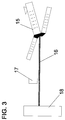
- FIG. 3 shows a basic possibility of how a vehicle tire (for example FIG. 1) can be manufactured with improved conductivity.
- the tread 16 (mixture composition Table 1) obtainable by an extrusion process 15 or at least the part of the tread which has a high specific resistance in the vulcanized state can also be used in the vulcanized one Conductive polymer plug state (mixture composition Table 2) are enforced.
- the conductive polymer plug can be introduced by means of an injection device 17.
- the tread 16 then passes through a cooling device 18 and is provided for further tire manufacture. In principle, it is also possible to cool the tread 16 before the polymer plug is injected.
- the conductive polymer plugs 7 made of unvulcanized rubber and / or plastic in solid form.
- pins made of unvulcanized rubber and / or plastic (mixture composition Table 2) z. B. with a diameter of 2 to 5 mm and a length that corresponds at least to the thickness of the tread part, which has a specific resistance greater than 10 exp 10 ohms x cm, below -80 ° C.
- Frozen should in principle be understood to mean temperatures around the glass transition temperature of the polymer plug mixture and below.
- the injection device 17 contains a cooling device and a ramming tool, so that the polymer plug material can be introduced into the uncured tread 16 in the frozen state by means of the ramming tool.
Landscapes
- Engineering & Computer Science (AREA)
- Mechanical Engineering (AREA)
- Tires In General (AREA)
Abstract
Description
Die Erfindung betrifft einen Fahrzeugreifen zur Montage auf eine elektrisch leitende Felge, der eine radial äußere Laufgummischicht aufweist, die einen spezifischen elektrischen Widerstand größer 10 exp 10 Ohm x cm besitzt.The invention relates to a vehicle tire for mounting on an electrically conductive rim, which has a radially outer rubber layer, which has a specific electrical resistance greater than 10
Bei einem Reifen mit einer Lauffläche, die eine geringe elektrische Leitfähigkeit aufweist, besteht das Problem, daß es während des Fahrbetriebes des Reifens zur elektrischen Aufladung der Lauffläche kommt. Mögliche Folgen einer solchen Aufladung können z. B. Funkenüberschläge sein, die im schlimmsten Falle zu einer Explosion führen können. Insbesondere bei Silica enthaltenden Laufflächen, die dem Reifen an sich gute Fahreigenschaften, wie einen geringen Rollwiderstand und gute Naßrutscheigenschaften verleihen, ist deren geringe elektrische Leitfähigkeit von bedauernswertem Nachteil.In the case of a tire with a tread which has low electrical conductivity, there is the problem that the tread is electrically charged while the tire is in operation. Possible consequences of such a charge can e.g. B. arcing, which in the worst case can lead to an explosion. Particularly in the case of treads containing silica, which in themselves give the tire good driving properties, such as low rolling resistance and good wet-sliding properties, their low electrical conductivity is an unfortunate disadvantage.
Es wurden Versuche unternommen, die elektrische Leitfähigkeit von Laufflächen zu erhöhen, indem eine dünne Schicht aus einer leitenden Gummimischung auf die nicht leitende Lauffläche aufgebracht wurde. Nachteilig dabei ist jedoch, daß während des Fahrbetriebes diese Schichten abgerieben werden können bzw. Risse in diesen Schichten auftreten. Damit besteht kein gesicherter Kontakt von der leitfähigen Schicht zur Straßenoberfläche. Weiterhin ist bekannt (EP 0 658 452 A1), eine leitfähige Schicht als umlaufendes Band durch die gesamte Dicke einer Lauffläche verlaufen zu lassen. Das hat aber den Nachteil, daß diese leitfähige Schicht eine durchgehende Mischungstrennschicht in der Lauffläche darstellt, die sich permanent im Bodenaufstandsbereich befindet. Durch den Fahrbetrieb des Reifens kann es zu einer Auftrennung der Lauffläche entlang dieser Mischungstrennschicht kommen. Somit wird sogar ein Defekt des Reifens verursacht.
Des weiteren sind Metalldrähte bekannt (DE-GM 19 92 389), die zur Ableitung von elektrostatischer Ladung in den Reifen eingebracht werden und bis an die Laufflächenoberfläche reichen. Aber aufgrund der geringen mechanischen Beständigkeit dieser Drähte und auftretender Haftprobleme zum Gummimaterial ist keine gesicherte Ableitung über die gesamte Lebensdauer einer Reifens gewährleistet. Außerdem sind derartige Drahtkonstruktionen z. B. für einen Gürtelreifen ungeeignet, da der Gürtel im Laufe des Fahrbetriebes durch starre Metalldrähte zerstört werden würde.Attempts have been made to increase the electrical conductivity of treads by applying a thin layer of a conductive rubber compound to the non-conductive tread. However, it is disadvantageous that these layers can be rubbed off during driving or cracks occur in these layers. This means there is no reliable contact from the conductive layer to the road surface. Furthermore, it is known (
Furthermore, metal wires are known (DE-GM 19 92 389), which are introduced into the tire to discharge electrostatic charge and extend to the tread surface. However, due to the low mechanical resistance of these wires and the problems with adhesion to the rubber material, no reliable derivation is guaranteed over the entire service life of a tire. In addition, such wire structures are such. B. unsuitable for a belt tire, since the belt would be destroyed by rigid metal wires in the course of driving.
Der Erfindung liegt nun die Aufgabe zugrunde, bei einem Reifen der eingangs genannten Art eine ausreichende elektrische Leitfähigkeit bereitzustellen, ohne dabei Einbußen in den Fahreigenschaften bzw. vorzeitige Defekte des Reifens hinzunehmen.The invention is based on the object of providing sufficient electrical conductivity in a tire of the type mentioned at the outset without sacrificing the driving properties or premature defects of the tire.
Gelöst wird diese Aufgabe dadurch, daß die Laufgummischicht im Bereich der Bodenaufstandsfläche des Reifens zumindest einen im wesentlichen radial verlaufenden Kanal aufweist, der mit einem Polymerpfropfen aus Gummi und/oder Kunststoff mit einem spezifischen elektrischen Widerstand kleiner 10 exp 8 Ohm x cm ausgefüllt ist, und daß dieser Polymerpfropfen zumindest die elektrisch schlecht leitende Laufgummischicht vollständig durchdringt.This object is achieved in that the tread rubber layer in the area of the ground contact area of the tire has at least one substantially radially extending channel which is filled with a polymer plug made of rubber and / or plastic with a specific electrical resistance of less than 10
Der Polymerpfropfen aus Gummi und/oder Kunststoff soll in dieser Anmeldung auch Mischungen aus verschiedenen Gummi- und/oder Kunststoffen beinhalten. Des weiteren kann der "Polymerpfropfen aus Gummi und/oder Kautschuk" für den Fachmann übliche Zusätze, wie z. B. Beschleuniger, Vernetzungsmittel, Füllstoffe und Pigmente enthalten.In this application, the polymer plug made of rubber and / or plastic is also intended to include mixtures of different rubber and / or plastics. Furthermore, the "Polymer stoppers made of rubber and / or rubber" for additives known to those skilled in the art, such as, for. B. accelerators, crosslinking agents, fillers and pigments.
Die erfindungsgemäßen elektrisch leitfähigen Polymerpfropfen reichen aus, um die während des Fahrbetriebes des Reifens aufgenommene elektrostatische Ladung an die Straßenoberfläche abzuleiten. Der wesentliche Anteil der aufgenommenen Ladungen verteilt sich anderenfalls über das gesamte Fahrgestell des Fahrzeuges, so daß eine gefährliche Ladung entsteht und es beim Betanken zur Explosion kommen kann. Die Ableitung findet über Felge, Seitenwand, Gürtelgummierung, ggf. Bandagengummierung und den erfindungsgemäßen Polymerpfropfen an die Straßenoberfläche statt. Da nur jeweils ein Polymerpfropfen, dessen Durchmesser zwischen 1 und 10 mm liegen soll, in der Bodenaufstandsfläche erforderlich ist, ist die Fläche des Polymerpfropfens auf den Reifenumfang bezogen, die mit der Fahrbahnoberfläche Kontakt hat, sehr gering. Deshalb können als Polymerpfropfenmaterial auch Gummi und/oder Kunststoffe verwendet werden, die keinen positiven Einfluß auf die Eigenschaften (z. B. Rollwiderstand, Naßrutschverhalten) des Reifens aufweisen, sofern deren elektrischer Widerstand kleiner 10 exp 8 Ohm x cm ist. Ein weiterer Vorteil des relativ geringen Durchmessers der Polymerpfropfen, der durch die nicht leitende Laufflächenoberfläche bis auf eine gut leitende Schicht reicht, besteht darin, daß ein Auseinandertrennen der gesamten Lauffläche aufgrund von ausgedehnten Mischungstrennschichten nicht möglich ist. Aufgrund der geometrischen Struktur (geringer Durchmesser) der Polymerpfropfen- wird ein Ausbröckeln des Polymerpfropfen aus der Lauffläche verhindert, da Haftungsprobleme keine Rolle spielen. Die Auswahl an einsetzbaren Mischungen für Polymerpfropfen und Laufflächen wird dadurch nicht beschränkt.The electrically conductive polymer plugs according to the invention are sufficient to discharge the electrostatic charge picked up during the driving operation of the tire to the road surface. The major part of the loaded loads is otherwise distributed over the entire chassis of the vehicle, so that a dangerous load is created and an explosion can occur when refueling. The discharge takes place via the rim, side wall, belt rubber, possibly rubber banding and the polymer plug according to the invention to the road surface. Since only one polymer plug, the diameter of which is between 1 and 10 mm, is required in the ground contact area, the area of the polymer plug is very small in relation to the circumference of the tire, which is in contact with the road surface. Therefore, rubber and / or plastics which do not have a positive influence on the properties (e.g. rolling resistance, wet skid behavior) of the tire can also be used as the polymer plug material, provided that their electrical resistance is less than 10
Die erfindungsgemäßen Polymerpfropfen können sowohl in Vollgummireifen als auch in Luftreifen eingebracht sein. Wenn es sich dabei um einen profilierten Reifen handelt, ist es vorteilhaft, wenn sich die Polymerpfropfen in Bereichen von erhabenen Profilabschnitten wie Klötzen oder Rippen befinden, da diese Profilelemente mit der Fahrbahnoberfläche in unmittelbarem Kontakt stehen und somit auftretende Ladungen sofort ableiten. Prinzipiell ist es aber auch möglich, Polymerpfropfen an nicht erhabenen Profilabschnitten (Rillen) einzubringen.The polymer plugs according to the invention can be introduced both in solid rubber tires and in pneumatic tires. If it is a profiled tire, it is advantageous if the polymer plugs are located in areas of raised tread sections such as blocks or ribs, since these tread elements are in direct contact with the road surface and thus immediately dissipate any charges that occur. In principle, however, it is also possible to insert polymer plugs on non-raised profile sections (grooves).
Der Polymerpfropfen soll einen spezifischen elektrischen Widerstand kleiner 10 exp 8 Ohm x cm aufweisen. Dafür eignet sich Gummi und/oder Kunststoff, der Ruß enthält. Insbesondere wird Ruß enthaltender Gummi bei der Reifenherstellung allgemein verwendet (z.B. als Gürtelgummierung), so daß eine zusätzliche Materialbereitstellung für die Polymerpfropfen entfallen kann. Es ist aber auch vorteilhaft, wenn die Polymerpfropfen aus Gummi oder Kunststoff bestehen, die leitende Polymere wie z. B. Polypyridine und/oder Polypyrrole und/oder Polyaniline enthalten. Dabei ist es auch möglich, diese genannten Substanzen allein als Polymerpfropfenmaterial einzusetzen. Diese Substanzen haben einen besonders niedrigen spezifischen elektrischen Widerstand, so daß der Durchmesser des Polymerpfropfens noch geringer gehalten werden kann, damit eine ausreichende Ableitung der elektrischen Ladung erfolgen kann. Das bringt den Vorteil mit sich, daß die Kontaktfläche, die der Polymerpfropfen zur Fahrbahnoberfläche hat, auch sehr klein ist, so daß die Fahreigenschaften des Reifens durch den Polymerpfropfen noch weniger beeinflußt werden.The polymer plug should have a specific electrical resistance of less than 10
Vorteilhaft ist es natürlich, wenn der Gummi und/oder Kunststoff des Polymerpfropfens einen besonders geringen spezifischen elektrischen Widerstand aufweist. Die Potentialdifferenz zwischen Boden und Fahrzeug ist in diesem Fall besonders hoch, was eine maximale Ableitung zur Folge hat. Vorteilhaft haben sich dabei spezifische elektrische Widerstände kleiner 100 Ohm x cm bewährt.It is of course advantageous if the rubber and / or plastic of the polymer plug has a particularly low specific electrical resistance. The The potential difference between the ground and the vehicle is particularly high in this case, which results in maximum dissipation. Specific electrical resistances of less than 100 ohm × cm have proven advantageous.
Besonders günstig ist es, wenn die äußere Laufgummischicht, die den Polymerpfropfen umgibt, eine Silica enthaltende Mischung ist. Dadurch werden die optimalen Fahreigenschaften (geringer Rollwiderstand, sehr gutes Naßrutschverhalten), die Silicamischungen mit sich bringen, ausgenutzt und gleichzeitig durch die Polymerpfropfen auch die schlechte elektrische Leitfähigkeit kompensiert. Generell können aber auch bisher bekannte Gummimischungen, die sich als äußere Laufgummischicht eignen und einen spezifischen elektrischen Widerstand größer 10 exp 10 Ohm x cm aufweisen mit Polymerpfropfen versehen werden.It is particularly favorable if the outer running rubber layer, which surrounds the polymer plug, is a mixture containing silica. As a result, the optimal driving properties (low rolling resistance, very good wet-slip behavior) that silica mixtures bring with them are exploited and, at the same time, the poor electrical conductivity is compensated for by the polymer plugs. In general, however, previously known rubber mixtures which are suitable as an outer running rubber layer and have a specific electrical resistance greater than 10
Der erfindungsgemäße Reifen mit Polymerpfropfen kann hergestellt werden, indem in den bereits vulkanisierten Reifen Polymerpfropfen aus vulkanisiertem Gummi und/oder Kunststoff mit einem spezifischen elektrischen Widerstand kleiner 10 exp 8 Ohm x cm mittels einer Injiziervorrichtung eingebracht werden, die sich zumindest durch den Teil der Laufgummischicht erstrecken, der einen spezifischen elektrischen Widerstand größer 10 exp 10 Ohm x cm aufweist. Um Polymerpfropfen in eine schlecht leitende Laufgummischicht vulkanisierter Reifen einzubringen, sind Kanäle im wesentlichen in radial innerer Richtung erforderlich, die z. B. durch ein Bohrwerkzeug, das einen Teil der Injiziervorrichtung bildet, erzeugt werden und die zumindest durch die gesamte schlecht leitende Laufgummischicht reichen. Vorzugsweise erstrecken sich die Kanäle bis an die Schicht im Reifeninneren, die den geringsten elektrischen Widerstand aufweist, um einen maximale Ladungsableitung zu erzielen. Die Variante des Einbringens von leitfähigen Polymerpfropfen in vulkanisierte Reifen bringt den Vorteil mit sich, daß gezielt in den erhabenen Profilabschnitten (Klötze, Rippen) leitfähige Polymerpfropfen eingebracht werden können, so daß eine Optimierung der Polymerpfropfenanzahl erreicht wird.The tire according to the invention with polymer plugs can be produced by introducing polymer plugs made of vulcanized rubber and / or plastic with a specific electrical resistance of less than 10
Eine andere Möglichkeit für die Herstellung des erfindungsgemäßen Reifens mit leitfähigen Polymerpfropfen besteht darin, in die schlecht leitende Laufgummischicht unvulkanisierter Reifen leitfähige Mischungen aus unvulkanisiertem Gummi und/oder Kunststoff einzubringen. Das kann mittels einer Injiziervorrichtung, die das leitfähgie Polymerpfropfenmaterial in Form von unvulkanisierten Gummimischungen und/oder Kunststoffmischungen oder Lösungen hieraus enthält. Es ist auch möglich, tiefgekühltes Polymerpfropfenmaterial zu injizieren. Der Vorteil des Einbringens von Polymerpfropfen in einen unvulkanisierten Reifen besteht darin, daß eventuell entstehender Materialabfall unvernetzt und damit wieder verwendbar ist. Des weiteren wird durch gemeinsame Vulkanisieren/Vernetzen von Laufstreifen und Polymerpfropfen eine optimale Haftung zwischen diese beiden Komponenten erreicht. Außerdem können im Gegensatz zum Stand der Technik (EP 0 658 452 A1), in dem im allgemeinen zusätzliche Extruder zum Extrudieren des leitfähigen umlaufenden Bandes erforderlich sind, beim Einbringen der erfindungsgemäßen Polymerpfropfen billigere Vorrichtungen eingesetzt werden.Another possibility for producing the tire according to the invention with conductive polymer plugs is to introduce conductive mixtures of unvulcanized rubber and / or plastic into the poorly conductive tread rubber layer of unvulcanized tires. This can be done by means of an injection device that contains the conductive polymer plug material in the form of unvulcanized rubber mixtures and / or plastic mixtures or solutions thereof. It is also possible to inject frozen polymer plug material. The advantage of introducing polymer plugs into an unvulcanized tire is that any material waste that arises is uncrosslinked and can therefore be reused. Furthermore, by vulcanizing / crosslinking the tread and the polymer plug together, optimum adhesion between these two components is achieved. In addition, in contrast to the prior art (
Prinzipiell können die Polymerpfropfen aus unvulkanisiertem Gummi und/oder Kunststoff auch in fertig gewickelten Reifenrohlingen eingebracht werden.In principle, the polymer plugs made of unvulcanized rubber and / or plastic can also be introduced into pre-wound tire blanks.
Das Einbringen von Polymerpfropfen in einem Reifen bzw. Reifenrohling eignet sich sowohl für Vollgummireifen als auch für Luftreifen.The insertion of polymer plugs in a tire or green tire is suitable both for solid rubber tires and for pneumatic tires.
Ein Ausführungsbeispiel wird anhand einer schematischen Zeichnung näher erläutert.An exemplary embodiment is explained in more detail with reference to a schematic drawing.
Es zeigt:
- Fig. 1:
- im Querschnitt einen Fahrzeugluftreifen mit leitfähigen Polymerpfropfen, der auf einer Felge montiert ist,
- Fig. 2:
- im Querschnitt einen Vollgummireifen mit leitenden Polymerpfropfen, der auf einer Felge montiert ist,
- Fig. 3:
- Verfahrensablauf zur Herstellung eines unvulkanisierten Laufstreifens mit leitendem Polymerpfropfen,
- Fig. 4:
- Verfahrensablauf zur Einbringung von Polymerpfropfen in einen unvulkanisierten Laufstreifen.
- Fig. 1:
- in cross section a pneumatic vehicle tire with conductive polymer plugs, which is mounted on a rim,
- Fig. 2:
- in cross section a solid rubber tire with conductive polymer plugs, which is mounted on a rim,
- Fig. 3:
- Process sequence for producing an unvulcanized tread with a conductive polymer plug,
- Fig. 4:
- Process sequence for introducing polymer plugs into an unvulcanized tread.
In der Figur 1 ist ein Fahrzeugluftreifen 1 mit Lauffäche 2, Gürtel 3, Karkasse 4, Seitenwand 5 und einem Wulst mit Wulstkernen 6 dargestellt, der auf einer Felge 8 montiert ist. In der Lauffläche 2 sind ausgehend von der äußeren schlecht leitenden Laufgummischicht nach radial innen verlaufende Kanäle, mit einem Durchmesser von z. B. 3 mm eingebracht, die mit leitendem Polymerpfropfen 7 ausgefüllt sind. Die Polymerpfropfen 7 sind in einem Abstand von maximal 10 cm voneinander entfernt, so daß zumindest ein Polymerpfropfen immer mit der Fahrbahn in Kontakt steht. Vorzugsweise sind die Polymerpfropfen 7 in den Profilklötzen des nicht dargestellten Profils der Lauffläche 2 eingebracht.1 shows a
Die äußere Laufgummischicht weist einen spezifischen elektrischen Widerstand von 10 exp 11 Ohm x cm (schlecht leitend) auf und hat folgende Zusammensetzung:
Die Polymerpfropfen 7 haben einen spezifischen elektrischen Widerstand von 60 Ohm x cm (gut leitend) und können z. B. folgende Zusammensetzung aufweisen:
Die Polymerpfropfen 7 in Figur 1 reichen von der Oberfläche der Lauffläche 2 bis zur nicht dargestellten Gürtelgummierung des Gürtels 3 des Fahrzeugluftreifens 1, da die Gürtelgummierung in den meisten Fällen bereits eine höhere elektrische Leitfähigkeit besitzt als die Lauffläche. Es ist natürlich auch denkbar, den Polymerpfropfen 7 bis direkt an den Gürtel 3 (metallische Festigkeitsträger) reichen zu lassen, da die Potentialdifferenz in diesem Fall besonders hoch ist und somit eine maximale Ladungsanzahl abgeführt wird. Prinzipiell ist es aber möglich, daß die Polymerpfropfen nur die äußerste Laufgummischicht durchdringen (z. B. Cap) und bis zu der nächsten Laufgummischicht (z. B. Base), die eine höhere Leitfähigkeit aufweist, reicht. Es ist natürlich auch möglich, die Polymerpfropfen an einer eventuell vorhandenen Bandagengummierung enden zu lassen. Die Ableitung der aufgenommenen elektrischen Ladungen erfolgt von der Felge über die vorhandenen elektrisch leitfähigen Gummischichten bzw. Festigkeitsträger bis hin zur Oberfläche der Fahrbahn.The polymer plugs 7 in FIG. 1 extend from the surface of the
Auch in Vollgummireifen 9, wie in Figur 2 dargestellt, der eine Lauffläche 11, eine kompressible Gummischicht 12, eine starre Gummischicht 13 und Drahtkerne 14 aufweist und an einer Felge 10 aufgebracht ist, lassen sich leitfähige Polymerpfropfen einbringen. Diese reichen von der äußersten Laufgummischicht vorteilhafterweise, wie in Figur 2 dargestellt, bis zur metallischen Felge 14 oder sie enden an einer elektrisch besser leitfähigeren Gummischicht 12 oder 13.Conductive polymer plugs can also be introduced into
Für die Herstellung des erfindungsgemäßen Vollgummireifens 9 nach Figur 2 (Polymerpfropfen reicht bis zur Felge) ist folgende -nicht dargestellte- Methode geeignet:
Mit einem Bohrwerkzeug wird ein bis zur Felge reichender Kanal erzeugt. Der vulkanisierte Gummi und/oder Kunststoff für den Polymerpfropfen mit einem Übermaß zur Bohrung wird von einer Wickeltrommel gezogen. Durch die Zugkraft verringert sich sein Durchmesser. Mittels einer Injiziervorrichtung, die ein drahtschlingenähnliches Gebilde zur Fassung des vulkanisierten Polymerpfropfens aufweist, wird der Polymerpfropfen durch die Bohrung gezogen. Der Polymerpfropfendurchmesser nimmt aufgrund der nachgelassenen Zugbeanspruchung zu, so daß der Polymerpfropfen fest im Kanal sitzt.The following method (not shown) is suitable for producing the
With a drilling tool, a channel reaching to the rim is created. The vulcanized rubber and / or plastic for the polymer plug with an oversize to the hole is pulled by a winding drum. Its diameter is reduced by the tensile force. The polymer plug is pulled through the bore by means of an injection device, which has a wire-loop-like structure for holding the vulcanized polymer plug. The polymer plug diameter increases due to the reduced tensile stress, so that the polymer plug sits firmly in the channel.
In der Figur 3 ist eine prinzipielle Möglichkeit ersichtlich, wie ein Fahrzeugreifen (z. B. Figur 1) mit einer verbesserten Leitfähigkeit hergestellt werden kann. So kann der durch ein Extrusionsverfahren 15 erhältliche Laufstreifen 16 (Mischungszusammensetzung Tabelle 1) bzw. zumindest der Teil des Laufstreifens, der im vulkanisiertem Zustand einen hohen spezifischen Widerstand aufweist, mit im vulkanisiertem Zustand leitfähigen Polymerpfropfen (Mischungszusammensetzung Tabelle 2) durchsetzt werden. Mittels einer Injiziervorrichtung 17 kann der leitende Polymerpfropfen eingebracht werden. Anschließend durchläuft der Laufstreifen 16 eine Kühleinrichtung 18 und wird für die weitere Reifenherstellung bereitgestellt. Prinzipiell ist es auch möglich, die Kühlung des Laufstreifens 16 bereits vor der Injizierung des Polymerpfropfens vorzunehmen.FIG. 3 shows a basic possibility of how a vehicle tire (for example FIG. 1) can be manufactured with improved conductivity. Thus, the tread 16 (mixture composition Table 1) obtainable by an
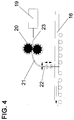
In der Figur 4 ist eine Variante einer Injiziervorrichtung 17 für die Einbringung von leitfähigen Polymerpfropfen in unvulkanisiertes Material (vgl. Figur 3) näher dargestellt. Aus einem Extruder oder Vorratsbehälter 19 wird der unvulkanisierte Gummi und/oder Kunststoff für den Polymerpfropfen (Tabelle 2) mittels einer Zahnradpumpe 20 direkt oder durch eine Leitung 23 zugeführt. Dabei kann es sich um viskose oder flüssige Mischungen aus Gummi und/oder Kunststoff oder Lösungen hieraus handeln. Für niederviskose Mischungen können niedermolekulare Polymere wie flüssiges Polyisopren oder Polybutadien verwendet werden. Die Zahnradpumpe 20 sorgt für einen gleichmäßigen Polymerpfropfenmaterialschub, der durch eine flexible Leitung 21 und eine Injizierkanüle mit Führungsrollen 22 in den fortlaufenden unvulkanisierten Laufstreifen 16 eingespritzt wird. Die Führungsrollen ermöglichen über eine Steuerung horizontale und/oder vertikale Bewegungen der Injizierkanüle, so daß z. B. Einstichtiefe und -zeit variiert werden können. Es werden somit Polymerpfropfen erzeugt, die im wesentlichen zylindrischen Charakter aufweisen. Im folgendem sind einige Verfahrensparameter angegeben:
- Kanülendurchmesser: 0,5 mm
- Einstechzeit: 0,01 s
- Herausziehzeit: 0,1 s
- Stichfrequenz: 3 mal/s
- Fließgeschwindigkeit in der Kanüle: 7 cm/s
- Cannula diameter: 0.5 mm
- Piercing time: 0.01 s
- Pull-out time: 0.1 s
- Stitch frequency: 3 times / s
- Flow rate in the cannula: 7 cm / s
Es ist außerdem noch möglich, die leitfähigen Polymerpfropfen 7 aus unvulkanisiertem Gummi und/oder Kunststoff in fester Form einzubringen. Dazu werden Stifte aus unvulkanisiertem Gummi und/oder Kunststoff (Mischungszusammensetzung Tabelle 2) z. B. mit einem Durchmesser von 2 bis 5 mm und einer Länge, die zumindest der Stärke des Laufstreifenteils, der einen spezifischen Widerstand größer 10 exp 10 Ohm x cm aufweist, entspricht, unter - 80°C tiefgekühlt. Unter tiefgekühlt sollen prinzipiell Temperaturen um die Glastemperatur der Polymerpfropfenmischung und darunter verstanden werden. Die Injiziervorrichtung 17 enthält eine Kühlvorrichtung und ein Rammwerkzeug, so daß das Polymerpfropfenmaterial im tiefgekühlten Zustand mittels des Rammwerkzeuges in den unvulkanisierten Laufstreifen 16 eingebracht werden kann. Dabei ist es möglich, die Bewegung des Laufstreifens 16 zur Injizierung des tiefgekühlten Polymerpfropfens anzuhalten oder aber die Laufstreifengeschwindigkeit mit der der Injiziervorrichtung zu koppeln. Da bei dieser Ausführungsvariante i. a. Material aus dem Laufstreifen 16 mittels des Rammwerkzeuges herausgetrieben wird und in diesen entstandenen Hohlraum der unvulkanisierte tiefgekühlte Stift eingesetzt wird, wird ein unkontrolliertes "Vermengen" von Laufstreifenmaterial und Stifmaterial vermieden und somit eine gesichtert Ableitung elektrostatischer Ladungen zur Fahrbahnoberfläche gewährleistet.It is also possible to introduce the conductive polymer plugs 7 made of unvulcanized rubber and / or plastic in solid form. For this purpose, pins made of unvulcanized rubber and / or plastic (mixture composition Table 2) z. B. with a diameter of 2 to 5 mm and a length that corresponds at least to the thickness of the tread part, which has a specific resistance greater than 10
Claims (13)
Applications Claiming Priority (2)
| Application Number | Priority Date | Filing Date | Title |
|---|---|---|---|
| DE19603441 | 1996-02-01 | ||
| DE19603441A DE19603441C2 (en) | 1996-02-01 | 1996-02-01 | Method for producing a vehicle tire |
Publications (3)
| Publication Number | Publication Date |
|---|---|
| EP0787604A2 true EP0787604A2 (en) | 1997-08-06 |
| EP0787604A3 EP0787604A3 (en) | 1998-01-28 |
| EP0787604B1 EP0787604B1 (en) | 2001-04-11 |
Family
ID=7784143
Family Applications (1)
| Application Number | Title | Priority Date | Filing Date |
|---|---|---|---|
| EP97101181A Expired - Lifetime EP0787604B1 (en) | 1996-02-01 | 1997-01-25 | Vehicle tyre |
Country Status (2)
| Country | Link |
|---|---|
| EP (1) | EP0787604B1 (en) |
| DE (2) | DE19603441C2 (en) |
Cited By (17)
| Publication number | Priority date | Publication date | Assignee | Title |
|---|---|---|---|---|
| EP0881060A2 (en) * | 1997-05-26 | 1998-12-02 | Bridgestone Corporation | Method and apparatus for the manufacture of pneumatic tyres having electric discharge means |
| EP0890460A1 (en) * | 1997-03-18 | 1999-01-13 | Bridgestone Corporation | Antistatic tire |
| EP0895877A1 (en) * | 1997-08-04 | 1999-02-10 | Bridgestone Corporation | Pneumatic tire |
| EP0995618A2 (en) * | 1998-10-19 | 2000-04-26 | The Goodyear Tire & Rubber Company | Tire with tread containing electrically conductive stitched thread |
| EP0995617A2 (en) * | 1998-10-19 | 2000-04-26 | The Goodyear Tire & Rubber Company | Tire with tread containing electrically conductive staples |
| WO2002022382A1 (en) * | 2000-09-15 | 2002-03-21 | Bridgestone/Firestone North American Tire, Llc | Conductive pathways in tire treads for reduced static charge buildup |
| US7029544B2 (en) | 2000-09-15 | 2006-04-18 | Bridgestone Firestone North American Tire, Llc | Conductive pathways in tire treads for reduced static charge buildup |
| EP1792720A2 (en) * | 2005-12-02 | 2007-06-06 | Sumitomo Rubber Industries Ltd. | Pneumatic tire and method of manufacturing same |
| US20080216929A1 (en) * | 2007-03-06 | 2008-09-11 | Toyo Tire & Rubber Co., Ltd. | Manufacturing method of pneumatic tire and pneumatic tire |
| US20090065114A1 (en) * | 2007-09-11 | 2009-03-12 | Solideal Holding Sa | Non-marking antistatic tire |
| EP2596964A1 (en) * | 2011-11-22 | 2013-05-29 | The Goodyear Tire & Rubber Company | Stiffness enhanced tread |
| WO2017144142A1 (en) * | 2016-02-26 | 2017-08-31 | Continental Reifen Deutschland Gmbh | Solid rubber tire |
| WO2018001498A1 (en) * | 2016-06-30 | 2018-01-04 | Artic Investments S.A. | Tire and method for making a tire |
| WO2018007061A1 (en) * | 2016-07-08 | 2018-01-11 | Continental Reifen Deutschland Gmbh | Solid rubber tire |
| FR3075695A3 (en) * | 2017-12-22 | 2019-06-28 | Compagnie Generale Des Etablissements Michelin | PNEUMATIC COMPRISING A PLURALITY OF CONDUCTIVE ANCHORS |
| EP3727897B1 (en) * | 2017-12-22 | 2021-12-01 | Compagnie Générale des Etablissements Michelin | Tyre comprising a conductive cord |
| EP4015202A3 (en) * | 2020-12-15 | 2023-05-03 | Continental Reifen Deutschland GmbH | Method for producing a solid tyre |
Families Citing this family (3)
| Publication number | Priority date | Publication date | Assignee | Title |
|---|---|---|---|---|
| DE19850766B4 (en) * | 1998-11-04 | 2004-01-22 | Continental Aktiengesellschaft | Vehicle tires |
| DE10154454C1 (en) * | 2001-11-06 | 2003-06-18 | Continental Ag | Solid rubber tire on rim has electrically-conductive body containing carbon black, surrounded by resistive clear rubber tread, locally-penetrated by body rubber |
| DE102005056248B4 (en) * | 2005-11-25 | 2012-01-12 | Siemens Ag | Selective main circuit breaker |
Citations (2)
| Publication number | Priority date | Publication date | Assignee | Title |
|---|---|---|---|---|
| DE1992389U (en) | 1968-06-04 | 1968-08-22 | Dipl-Ing Franz Morgenstern 8000 München | Motor vehicle with a device for preventing the electric charging of the rubber-tired motor vehicle |
| EP0658452A1 (en) | 1993-12-14 | 1995-06-21 | PIRELLI COORDINAMENTO PNEUMATICI S.p.A. | Antistatic tyre having low-carbon black blends |
Family Cites Families (6)
| Publication number | Priority date | Publication date | Assignee | Title |
|---|---|---|---|---|
| GB544757A (en) * | 1940-02-15 | 1942-04-27 | Us Rubber Co | Improvements in a pneumatic tyre and method of making same |
| GB551657A (en) * | 1940-12-19 | 1943-03-04 | Firestone Tire & Rubber Co | Improvements in or relating to rubber tires |
| FR1279913A (en) * | 1959-06-29 | 1961-12-29 | Electrical connection device between a vehicle and the ground | |
| JP2782073B2 (en) * | 1989-02-01 | 1998-07-30 | 横浜ゴム株式会社 | Radial ply tires for passenger cars |
| DE4417914A1 (en) * | 1994-05-21 | 1995-11-23 | Ralf Schoeppe | Electrostatic charge build-up prevention system for metallic vehicles on rubber tyres |
| DE4447823B4 (en) * | 1994-12-21 | 2007-07-26 | Dunlop Gmbh | Vehicle tires and process for its manufacture |
-
1996
- 1996-02-01 DE DE19603441A patent/DE19603441C2/en not_active Expired - Fee Related
-
1997
- 1997-01-25 DE DE59703326T patent/DE59703326D1/en not_active Expired - Lifetime
- 1997-01-25 EP EP97101181A patent/EP0787604B1/en not_active Expired - Lifetime
Patent Citations (2)
| Publication number | Priority date | Publication date | Assignee | Title |
|---|---|---|---|---|
| DE1992389U (en) | 1968-06-04 | 1968-08-22 | Dipl-Ing Franz Morgenstern 8000 München | Motor vehicle with a device for preventing the electric charging of the rubber-tired motor vehicle |
| EP0658452A1 (en) | 1993-12-14 | 1995-06-21 | PIRELLI COORDINAMENTO PNEUMATICI S.p.A. | Antistatic tyre having low-carbon black blends |
Cited By (31)
| Publication number | Priority date | Publication date | Assignee | Title |
|---|---|---|---|---|
| EP0890460A1 (en) * | 1997-03-18 | 1999-01-13 | Bridgestone Corporation | Antistatic tire |
| US6183581B1 (en) | 1997-03-18 | 2001-02-06 | Bridgestone Corporationn | Antistatic tire |
| EP0881060A2 (en) * | 1997-05-26 | 1998-12-02 | Bridgestone Corporation | Method and apparatus for the manufacture of pneumatic tyres having electric discharge means |
| EP0881060A3 (en) * | 1997-05-26 | 1999-12-22 | Bridgestone Corporation | Method and apparatus for the manufacture of pneumatic tyres having electric discharge means |
| EP0895877A1 (en) * | 1997-08-04 | 1999-02-10 | Bridgestone Corporation | Pneumatic tire |
| US6367525B1 (en) | 1997-08-04 | 2002-04-09 | Bridgestone Corporation | Pneumatic tire and method of making tire |
| EP0995617A3 (en) * | 1998-10-19 | 2000-12-27 | The Goodyear Tire & Rubber Company | Tire with tread containing electrically conductive staples |
| EP0995618A3 (en) * | 1998-10-19 | 2000-12-27 | The Goodyear Tire & Rubber Company | Tire with tread containing electrically conductive stitched thread |
| EP0995617A2 (en) * | 1998-10-19 | 2000-04-26 | The Goodyear Tire & Rubber Company | Tire with tread containing electrically conductive staples |
| US6220319B1 (en) | 1998-10-19 | 2001-04-24 | The Goodyear Tire & Rubber Company | Tire with tread containing electrically conductive staples |
| US6289958B1 (en) | 1998-10-19 | 2001-09-18 | The Goodyear Tire & Rubber Company | Tire with tread containing electrically conductive stitched thread |
| EP0995618A2 (en) * | 1998-10-19 | 2000-04-26 | The Goodyear Tire & Rubber Company | Tire with tread containing electrically conductive stitched thread |
| WO2002022382A1 (en) * | 2000-09-15 | 2002-03-21 | Bridgestone/Firestone North American Tire, Llc | Conductive pathways in tire treads for reduced static charge buildup |
| US7029544B2 (en) | 2000-09-15 | 2006-04-18 | Bridgestone Firestone North American Tire, Llc | Conductive pathways in tire treads for reduced static charge buildup |
| EP1792720A2 (en) * | 2005-12-02 | 2007-06-06 | Sumitomo Rubber Industries Ltd. | Pneumatic tire and method of manufacturing same |
| EP1792720A3 (en) * | 2005-12-02 | 2008-02-27 | Sumitomo Rubber Industries Ltd. | Pneumatic tire and method of manufacturing same |
| US20080216929A1 (en) * | 2007-03-06 | 2008-09-11 | Toyo Tire & Rubber Co., Ltd. | Manufacturing method of pneumatic tire and pneumatic tire |
| US20090065114A1 (en) * | 2007-09-11 | 2009-03-12 | Solideal Holding Sa | Non-marking antistatic tire |
| EP2036704A1 (en) * | 2007-09-11 | 2009-03-18 | Solideal Holding Sa | Non-marking antistatic tire |
| US8356646B2 (en) | 2007-09-11 | 2013-01-22 | Artic Investments S.A. | Non-marking antistatic tire |
| EP2596964A1 (en) * | 2011-11-22 | 2013-05-29 | The Goodyear Tire & Rubber Company | Stiffness enhanced tread |
| WO2017144142A1 (en) * | 2016-02-26 | 2017-08-31 | Continental Reifen Deutschland Gmbh | Solid rubber tire |
| CN112590469A (en) * | 2016-06-30 | 2021-04-02 | 阿蒂克投资股份有限公司 | Tyre for vehicle wheels |
| EP3750699A1 (en) * | 2016-06-30 | 2020-12-16 | Artic Investments S.A. | Tire and method for making a tire |
| WO2018001498A1 (en) * | 2016-06-30 | 2018-01-04 | Artic Investments S.A. | Tire and method for making a tire |
| CN112590469B (en) * | 2016-06-30 | 2023-01-17 | 米其林集团总公司 | Tyre for vehicle wheels |
| WO2018007061A1 (en) * | 2016-07-08 | 2018-01-11 | Continental Reifen Deutschland Gmbh | Solid rubber tire |
| CN109414960A (en) * | 2016-07-08 | 2019-03-01 | 大陆轮胎德国有限公司 | Vehicle tyre |
| FR3075695A3 (en) * | 2017-12-22 | 2019-06-28 | Compagnie Generale Des Etablissements Michelin | PNEUMATIC COMPRISING A PLURALITY OF CONDUCTIVE ANCHORS |
| EP3727897B1 (en) * | 2017-12-22 | 2021-12-01 | Compagnie Générale des Etablissements Michelin | Tyre comprising a conductive cord |
| EP4015202A3 (en) * | 2020-12-15 | 2023-05-03 | Continental Reifen Deutschland GmbH | Method for producing a solid tyre |
Also Published As
| Publication number | Publication date |
|---|---|
| EP0787604A3 (en) | 1998-01-28 |
| DE19603441A1 (en) | 1997-08-07 |
| EP0787604B1 (en) | 2001-04-11 |
| DE59703326D1 (en) | 2001-05-17 |
| DE19603441C2 (en) | 1999-12-23 |
Similar Documents
| Publication | Publication Date | Title |
|---|---|---|
| EP0787604B1 (en) | Vehicle tyre | |
| DE19718699C1 (en) | Tyre building process to give tread with a path for discharge of static electricity | |
| DE102008012841B4 (en) | Pneumatic tires and method of making such pneumatic tires | |
| EP2027991B1 (en) | Method for manufacturing a pneumatic tyre for a vehicle. | |
| DE19520996C2 (en) | Vehicle tires with charge diversion | |
| EP3288781B1 (en) | Pneumatic vehicle tire having a tread | |
| DE102008053464A1 (en) | tire | |
| EP3288780B1 (en) | Pneumatic vehicle tire having a tread | |
| EP3103661B1 (en) | Method for manufacturing an electrically conductive passage in a vehicle tyre | |
| EP0798142A1 (en) | Vehicle tyre | |
| DE102007039100A1 (en) | Vehicle pneumatic tire producing tread cap as extruded profile, attaching or affixing electrically conductive material on cut surface of tread parts and/or cap parts, and joining tread parts and/or cap parts | |
| DE19644538C1 (en) | Pneumatic vehicle tires | |
| EP3653360B1 (en) | Preform device and method for producing a vehicle tyre with a strip comprising at least two rubber components | |
| EP3012095A1 (en) | Method for manufacturing a pneumatic tyre for a vehicle and pneumatic tyre for a vehicle | |
| DE102010037711B4 (en) | Process for manufacturing a pneumatic vehicle tire | |
| DE2733518A1 (en) | METHOD AND DEVICE FOR RENEWING A TIRE | |
| DE102007022147A1 (en) | Method for producing vehicle tires with radial fibers in tread comprises cutting rubber composition strip containing longitudinally oriented fibers transversely into sections and turning them through ninety degrees before assembly | |
| DE102006050840B4 (en) | Method for producing a pneumatic vehicle tire | |
| EP0931678A2 (en) | Vehicle tyre | |
| EP3475070B1 (en) | Method for producing a solid rubber tyre and solid rubber tyre produced according to said method | |
| DE2624585A1 (en) | METHOD AND APPARATUS FOR MANUFACTURING A LAMINATED TAPE FROM AN UNVULCANIZED ELASTOMER FOR VULCANIZING INTO A MOLD FOR THE PURPOSE OF MANUFACTURING A TIRE | |
| EP3321109B1 (en) | Pneumatic tyre for a vehicle | |
| EP1918132B1 (en) | Method for manufacturing a pneumatic tyre for a vehicle and pneumatic tyre for a vehicle | |
| DE102022213081A1 (en) | Process for introducing thin elements with improved electrical conductivity into an extrudate | |
| EP3760424B1 (en) | Method for the production of a pneumatic vehicle tyre, use of strip winding for winding one or more rubber components, device for carrying out the method and a pneumatic vehicle tyre which is produced or can be produced according to the method |
Legal Events
| Date | Code | Title | Description |
|---|---|---|---|
| PUAI | Public reference made under article 153(3) epc to a published international application that has entered the european phase |
Free format text: ORIGINAL CODE: 0009012 |
|
| AK | Designated contracting states |
Kind code of ref document: A2 Designated state(s): DE FR GB IT |
|
| PUAL | Search report despatched |
Free format text: ORIGINAL CODE: 0009013 |
|
| AK | Designated contracting states |
Kind code of ref document: A3 Designated state(s): DE FR GB IT |
|
| 17P | Request for examination filed |
Effective date: 19980728 |
|
| 17Q | First examination report despatched |
Effective date: 19991209 |
|
| GRAG | Despatch of communication of intention to grant |
Free format text: ORIGINAL CODE: EPIDOS AGRA |
|
| GRAG | Despatch of communication of intention to grant |
Free format text: ORIGINAL CODE: EPIDOS AGRA |
|
| GRAH | Despatch of communication of intention to grant a patent |
Free format text: ORIGINAL CODE: EPIDOS IGRA |
|
| GRAH | Despatch of communication of intention to grant a patent |
Free format text: ORIGINAL CODE: EPIDOS IGRA |
|
| GRAA | (expected) grant |
Free format text: ORIGINAL CODE: 0009210 |
|
| AK | Designated contracting states |
Kind code of ref document: B1 Designated state(s): DE FR GB IT |
|
| REF | Corresponds to: |
Ref document number: 59703326 Country of ref document: DE Date of ref document: 20010517 |
|
| ITF | It: translation for a ep patent filed | ||
| GBT | Gb: translation of ep patent filed (gb section 77(6)(a)/1977) |
Effective date: 20010705 |
|
| ET | Fr: translation filed | ||
| REG | Reference to a national code |
Ref country code: GB Ref legal event code: IF02 |
|
| PLBE | No opposition filed within time limit |
Free format text: ORIGINAL CODE: 0009261 |
|
| STAA | Information on the status of an ep patent application or granted ep patent |
Free format text: STATUS: NO OPPOSITION FILED WITHIN TIME LIMIT |
|
| 26N | No opposition filed | ||
| PGFP | Annual fee paid to national office [announced via postgrant information from national office to epo] |
Ref country code: GB Payment date: 20070119 Year of fee payment: 11 |
|
| PGFP | Annual fee paid to national office [announced via postgrant information from national office to epo] |
Ref country code: IT Payment date: 20070625 Year of fee payment: 11 |
|
| PGFP | Annual fee paid to national office [announced via postgrant information from national office to epo] |
Ref country code: FR Payment date: 20070111 Year of fee payment: 11 |
|
| GBPC | Gb: european patent ceased through non-payment of renewal fee |
Effective date: 20080125 |
|
| REG | Reference to a national code |
Ref country code: FR Ref legal event code: ST Effective date: 20081029 |
|
| PG25 | Lapsed in a contracting state [announced via postgrant information from national office to epo] |
Ref country code: GB Free format text: LAPSE BECAUSE OF NON-PAYMENT OF DUE FEES Effective date: 20080125 |
|
| PG25 | Lapsed in a contracting state [announced via postgrant information from national office to epo] |
Ref country code: FR Free format text: LAPSE BECAUSE OF NON-PAYMENT OF DUE FEES Effective date: 20080131 |
|
| PG25 | Lapsed in a contracting state [announced via postgrant information from national office to epo] |
Ref country code: IT Free format text: LAPSE BECAUSE OF NON-PAYMENT OF DUE FEES Effective date: 20080125 |
|
| PGFP | Annual fee paid to national office [announced via postgrant information from national office to epo] |
Ref country code: DE Payment date: 20110121 Year of fee payment: 15 |
|
| PG25 | Lapsed in a contracting state [announced via postgrant information from national office to epo] |
Ref country code: DE Free format text: LAPSE BECAUSE OF NON-PAYMENT OF DUE FEES Effective date: 20120801 |
|
| REG | Reference to a national code |
Ref country code: DE Ref legal event code: R119 Ref document number: 59703326 Country of ref document: DE Effective date: 20120801 |