EP0787603B1 - A radial ply pneumatic tire - Google Patents
A radial ply pneumatic tire Download PDFInfo
- Publication number
- EP0787603B1 EP0787603B1 EP97107255A EP97107255A EP0787603B1 EP 0787603 B1 EP0787603 B1 EP 0787603B1 EP 97107255 A EP97107255 A EP 97107255A EP 97107255 A EP97107255 A EP 97107255A EP 0787603 B1 EP0787603 B1 EP 0787603B1
- Authority
- EP
- European Patent Office
- Prior art keywords
- tire
- rubber
- ply
- parts
- fillers
- Prior art date
- Legal status (The legal status is an assumption and is not a legal conclusion. Google has not performed a legal analysis and makes no representation as to the accuracy of the status listed.)
- Expired - Lifetime
Links
Images


Classifications
-
- B—PERFORMING OPERATIONS; TRANSPORTING
- B60—VEHICLES IN GENERAL
- B60C—VEHICLE TYRES; TYRE INFLATION; TYRE CHANGING; CONNECTING VALVES TO INFLATABLE ELASTIC BODIES IN GENERAL; DEVICES OR ARRANGEMENTS RELATED TO TYRES
- B60C3/00—Tyres characterised by the transverse section
-
- B—PERFORMING OPERATIONS; TRANSPORTING
- B60—VEHICLES IN GENERAL
- B60C—VEHICLE TYRES; TYRE INFLATION; TYRE CHANGING; CONNECTING VALVES TO INFLATABLE ELASTIC BODIES IN GENERAL; DEVICES OR ARRANGEMENTS RELATED TO TYRES
- B60C15/00—Tyre beads, e.g. ply turn-up or overlap
- B60C15/04—Bead cores
-
- B—PERFORMING OPERATIONS; TRANSPORTING
- B60—VEHICLES IN GENERAL
- B60C—VEHICLE TYRES; TYRE INFLATION; TYRE CHANGING; CONNECTING VALVES TO INFLATABLE ELASTIC BODIES IN GENERAL; DEVICES OR ARRANGEMENTS RELATED TO TYRES
- B60C13/00—Tyre sidewalls; Protecting, decorating, marking, or the like, thereof
-
- B—PERFORMING OPERATIONS; TRANSPORTING
- B60—VEHICLES IN GENERAL
- B60C—VEHICLE TYRES; TYRE INFLATION; TYRE CHANGING; CONNECTING VALVES TO INFLATABLE ELASTIC BODIES IN GENERAL; DEVICES OR ARRANGEMENTS RELATED TO TYRES
- B60C15/00—Tyre beads, e.g. ply turn-up or overlap
- B60C15/06—Flipper strips, fillers, or chafing strips and reinforcing layers for the construction of the bead
-
- B—PERFORMING OPERATIONS; TRANSPORTING
- B60—VEHICLES IN GENERAL
- B60C—VEHICLE TYRES; TYRE INFLATION; TYRE CHANGING; CONNECTING VALVES TO INFLATABLE ELASTIC BODIES IN GENERAL; DEVICES OR ARRANGEMENTS RELATED TO TYRES
- B60C17/00—Tyres characterised by means enabling restricted operation in damaged or deflated condition; Accessories therefor
- B60C17/0009—Tyres characterised by means enabling restricted operation in damaged or deflated condition; Accessories therefor comprising sidewall rubber inserts, e.g. crescent shaped inserts
- B60C17/0018—Tyres characterised by means enabling restricted operation in damaged or deflated condition; Accessories therefor comprising sidewall rubber inserts, e.g. crescent shaped inserts two or more inserts in each sidewall portion
-
- B—PERFORMING OPERATIONS; TRANSPORTING
- B60—VEHICLES IN GENERAL
- B60C—VEHICLE TYRES; TYRE INFLATION; TYRE CHANGING; CONNECTING VALVES TO INFLATABLE ELASTIC BODIES IN GENERAL; DEVICES OR ARRANGEMENTS RELATED TO TYRES
- B60C1/00—Tyres characterised by the chemical composition or the physical arrangement or mixture of the composition
- B60C2001/0033—Compositions of the sidewall inserts, e.g. for runflat
-
- B—PERFORMING OPERATIONS; TRANSPORTING
- B60—VEHICLES IN GENERAL
- B60C—VEHICLE TYRES; TYRE INFLATION; TYRE CHANGING; CONNECTING VALVES TO INFLATABLE ELASTIC BODIES IN GENERAL; DEVICES OR ARRANGEMENTS RELATED TO TYRES
- B60C15/00—Tyre beads, e.g. ply turn-up or overlap
- B60C15/0009—Tyre beads, e.g. ply turn-up or overlap features of the carcass terminal portion
- B60C2015/009—Height of the carcass terminal portion defined in terms of a numerical value or ratio in proportion to section height
-
- Y—GENERAL TAGGING OF NEW TECHNOLOGICAL DEVELOPMENTS; GENERAL TAGGING OF CROSS-SECTIONAL TECHNOLOGIES SPANNING OVER SEVERAL SECTIONS OF THE IPC; TECHNICAL SUBJECTS COVERED BY FORMER USPC CROSS-REFERENCE ART COLLECTIONS [XRACs] AND DIGESTS
- Y10—TECHNICAL SUBJECTS COVERED BY FORMER USPC
- Y10T—TECHNICAL SUBJECTS COVERED BY FORMER US CLASSIFICATION
- Y10T152/00—Resilient tires and wheels
- Y10T152/10—Tires, resilient
- Y10T152/10495—Pneumatic tire or inner tube
- Y10T152/10765—Characterized by belt or breaker structure
- Y10T152/10783—Reinforcing plies made up from wound narrow ribbons
-
- Y—GENERAL TAGGING OF NEW TECHNOLOGICAL DEVELOPMENTS; GENERAL TAGGING OF CROSS-SECTIONAL TECHNOLOGIES SPANNING OVER SEVERAL SECTIONS OF THE IPC; TECHNICAL SUBJECTS COVERED BY FORMER USPC CROSS-REFERENCE ART COLLECTIONS [XRACs] AND DIGESTS
- Y10—TECHNICAL SUBJECTS COVERED BY FORMER USPC
- Y10T—TECHNICAL SUBJECTS COVERED BY FORMER US CLASSIFICATION
- Y10T152/00—Resilient tires and wheels
- Y10T152/10—Tires, resilient
- Y10T152/10495—Pneumatic tire or inner tube
- Y10T152/10819—Characterized by the structure of the bead portion of the tire
- Y10T152/10828—Chafer or sealing strips
-
- Y—GENERAL TAGGING OF NEW TECHNOLOGICAL DEVELOPMENTS; GENERAL TAGGING OF CROSS-SECTIONAL TECHNOLOGIES SPANNING OVER SEVERAL SECTIONS OF THE IPC; TECHNICAL SUBJECTS COVERED BY FORMER USPC CROSS-REFERENCE ART COLLECTIONS [XRACs] AND DIGESTS
- Y10—TECHNICAL SUBJECTS COVERED BY FORMER USPC
- Y10T—TECHNICAL SUBJECTS COVERED BY FORMER US CLASSIFICATION
- Y10T152/00—Resilient tires and wheels
- Y10T152/10—Tires, resilient
- Y10T152/10495—Pneumatic tire or inner tube
- Y10T152/10819—Characterized by the structure of the bead portion of the tire
- Y10T152/10837—Bead characterized by the radial extent of apex, flipper or chafer into tire sidewall
-
- Y—GENERAL TAGGING OF NEW TECHNOLOGICAL DEVELOPMENTS; GENERAL TAGGING OF CROSS-SECTIONAL TECHNOLOGIES SPANNING OVER SEVERAL SECTIONS OF THE IPC; TECHNICAL SUBJECTS COVERED BY FORMER USPC CROSS-REFERENCE ART COLLECTIONS [XRACs] AND DIGESTS
- Y10—TECHNICAL SUBJECTS COVERED BY FORMER USPC
- Y10T—TECHNICAL SUBJECTS COVERED BY FORMER US CLASSIFICATION
- Y10T152/00—Resilient tires and wheels
- Y10T152/10—Tires, resilient
- Y10T152/10495—Pneumatic tire or inner tube
- Y10T152/10855—Characterized by the carcass, carcass material, or physical arrangement of the carcass materials
- Y10T152/10864—Sidewall stiffening or reinforcing means other than main carcass plies or foldups thereof about beads
Definitions
- This invention relates to a tire; more particularly to a pneumatic tire capable of being used in the uninflated condition.
- US-A-4 917 164 shows another approach, which corresponds to the preamble of claim 1.
- Applicants have discovered a new invention which permits a tire construction to be built which can be operated in the uninflated condition for extended distances at relatively high speeds after which the tire can be repaired and returned to normal use, while at the same time maintaining the desired performance of the tire in the inflated state.
- a radial ply pneumatic tire as described in the appended claims has an axis of rotation, a tread having a pair of lateral edges, a pair of reinforcing belts located radially inward of the tread, a pair of sidewalls extending radially inwardly from each lateral edge, a maximum section width defined as the maximum axial distance as measured from the outer surfaces of the sidewalls, and a tire carcass structure.
- Axial and “axially” means the lines or directions that are parallel to the axis of rotation of the tire.
- Bead means that part of the tire comprising an annular tensile member wrapped by ply cords and shaped, with or without other reinforcement elements such as flippers, chippers, apexes, toe guards and chafers, to fit the design rim.
- Belt Structure or “Reinforcing Belts” means at least two annular layers or plies of parallel cords, woven or unwoven, underlying the tread, unanchored to the bead, and having both left and right cord angles in the range from 17° to 27° with respect to the equatorial plane of the tire.
- “Circumferential” means lines or directions extending along the perimeter of the surface of the annular tread perpendicular to the axial direction.
- Carcass means the tire structure apart from the belt structure, tread, undertread, and sidewall rubber over the plies, but including the beads.
- Chips refers to narrow strips of material placed around the outside of the bead to protect cord plies from the rim, distribute flexing above the rim, and to seal the tire.
- Core means one of the reinforcement strands of which the plies in the tire are comprised.
- Equatorial Plane means the plane perpendicular to the tire's axis of rotation and passing through the center of its tread.
- “Footprint” means the contact patch or area of contact of the tire tread with a flat surface at zero speed and under normal load and pressure.
- Innerliner means the layer or layers of elastomer or other material that form the inside surface of a tubeless tire and that contain the inflating fluid within the tire.
- Normal Inflation Pressure means the specific design inflation pressure and load assigned by the appropriate standards organization for the service condition for the tire.
- Normal Load means the specific load assigned by the appropriate standards organization for the service condition for the tire.
- Ply means a continuous layer of rubber-coated parallel cords.
- Ring and radially mean directions radially toward or away from the axis of rotation of the tire.
- Ring Ply Tire means a belted or circumferentially-restricted pneumatic tire in which the ply cords which extend from bead to bead are laid at cord angles between 65° and 90° with respect to the equatorial plane of the tire.
- “Section Height” means the radial distance from the nominal rim diameter to the outer diameter of the tire at its equatorial plane.
- “Section Width” means the maximum linear distance parallel to the axis of the tire and between the exterior of its sidewalls when and after it has been inflated at normal pressure for 24 hours, but unloaded, excluding elevations of the sidewalls due to labeling, decoration or protective bands.
- Shader means the upper portion of sidewall just below the tread edge.
- “Sidewall” means that portion of a tire between the tread and the bead.
- Thread Width means the arc length of the tread surface in the axial direction, that is, in a plane parallel to the axis of rotation of the tire.
- the tire 10 is a passenger tire; the tire 10 is provided with a ground-engaging tread portion 12 which terminates in the shoulder portions 14,16 at the lateral edges of the tread respectively. Sidewall portion 18,20 extends from shoulder portion 14,16 respectively and terminates in a pair of bead portions 22,22' each having an annular inextensible bead core 26,26' respectively.
- the tire 10 is further provided with a carcass reinforcing structure 30 which extends from bead portion 22 through sidewall portion 18, tread portion 12, sidewall portion 20 to bead portion 22'.
- the turnup ends 32,34,32',34' of carcass reinforcing structure 30 are wrapped about bead cores 26,26' respectively.
- the tire 10 may include a conventional inner liner 35 forming the inner peripheral surface of the tire 10 if the tire is to be of the tubeless type.
- a tread reinforcing belt structure 36 Placed circumferentially about the radially outer surface of carcass reinforcing structure 30 beneath tread portion 12 is a tread reinforcing belt structure 36.
- belt structure 36 comprises two cut belt plies 50,51 and the cords of belt plies 50,51 are oriented at an angle of about 23 degrees with respect to the mid-circumferential centerplane of the tire.
- the cords of belt ply 50 are disposed in an opposite direction to the mid-circumferential centerplane and from that of the cords of belt ply 51.
- the belt structure 36 may comprise any number of belt plies of any desired configuration and the cords may be disposed at any desired angle.
- Belt structure 36 has a lateral stiffness across the belt width so as to minimize lifting of the tread from the road surface during operation of the tire in the uninflated state. In the embodiment illustrated, this is accomplished by making the cords of belt plies 51,52 of steel and preferably of a steel cable construction.
- the carcass reinforcing structure comprises at least two reinforcing ply structures.
- a radially inner first reinforcing ply structure 38 and a radially outer second reinforcing ply structure 40 each ply structure 38,40 comprising one layer of parallel cords.
- the cords 41 of reinforcing ply structure 38,40 are oriented at an angle of at least 75 degrees with respect to the mid-circumferential centerplane CP of the tire 10. In the particular embodiment illustrated, the cords 41 are oriented at an angle of about 90 degrees with respect to the mid-circumferential centerplane CP.
- the cords 41 may be made of any material normally used for cord reinforcement of rubber articles, for example, and not by way of limitation, rayon, nylon and polyester. Preferably, the cords are made of material having a high adhesion property with rubber and high heat resistance. In the particular embodiment illustrated, the cords 41 are made from rayon.
- the first and second reinforcing ply structure 38,40 each preferably comprise a single ply layer, however, any number of carcass plies may be used.
- the first and second reinforcing ply structure 38,40 have turnup ends 32,34 and 32',34' respectively which wrap about the bead core 26 and 26' respectively.
- the turnup ends 34,34' of the second ply 40 are adjacent to the bead core 26,26' and terminates radially above the bead core 26,26'.
- the turnup ends 32,32' of the first ply 38 wrap about the second ply turnup ends 34,34' and the bead core 26,26'.
- the turnup ends 34,34' of the first ply terminates radially a distance E above the nominal rim diameter of the tire in proximity to the radial location of the maximum section width of the tire.
- the turnup ends 34,34' are located within 20% of the section height of the tire from the radial location of the maximum section width, most preferably terminating at the radial location of the maximum section width.
- turnup ends 32,32' can terminate as described above in proximity of the radial location of the maximum section width.
- the turnup end 34,34' of the first ply 38 can be radially above or below the second ply turnup end 32,32'.
- the bead portions 22,22' of the tire 10 each have an annular substantially inextensible bead core 26,26' respectively.
- the bead core 26,26' has a flat base surface 27,27' defined by an imaginary surface tangent to the radially innermost surfaces of the bead wires.
- the flat base surface 27,27' has a pair of edges 28,29 and a width "W" between the edges.
- the bead core has an axially inner first surface 23 extending radially from edge 28 and an axially outer second surface 25 extending radially from edge 29.
- the first surface 23 and the flat base surface 27,27' form an acute included angle ⁇ .
- the second surface 25 and the flat base surface 27,27' form an acute included angle ⁇ .
- the angle ⁇ is greater than or equal to the angle ⁇ . In the preferred embodiment, ⁇ approximately equals ⁇ .
- the bead core 26,26' may further include a radially outer surface 31 extending between the first and second surfaces 23,25 respectively.
- the radial outer surface 31 has a maximum height H.
- the height H is less than the width of the base "W.”
- the cross-section defined by surfaces 23,25,27, and 31 preferably are in the form of the base portion of an isosceles triangle.
- the upper portion of the triangular shape cross-section is generally not required because the strength of the core 26,26' as illustrated is sufficient to restrain the beads of an uninflated tire on the rim.
- the bead core is preferably constructed of a single or monofilament steel wire continuously wrapped.
- the bead construction is as described in EP-A-0590481.
- the flat base surfaces of the bead cores 26,26' are preferably about parallel relative to the axis of rotation, while the bottom of the molded portion of the bead is inclined, the preferred inclination being approximately 5° to 10.5° relative to the axis of rotation.
- the inclination of the bead portion assists sealing the tire and is complimentary to the inclination of the bead seat flange of a conventional rim and is believed to assist retaining the beads seated to the rim.
- elastomeric fillers 48 Located within the bead portions 22,22' and the radially inner portions of the sidewall portions 16,18 are high modulus elastomeric fillers 48 disposed between carcass reinforcing structure 30 and the turnup ends 32,34 and 32',34' respectively.
- the elastomeric fillers 48 extend from the radially outer portion of bead cores 26,26' respectively, up into the sidewall portion gradually decreasing in cross-sectional width.
- the elastomeric inserts 48 terminate a distance G from the nominal rim diameter NRD of at least 25 percent (25%) of the section height SH of the tire.
- the elastomeric fillers 48 each extend radially outward from the nominal rim diameter NRD a distance of approximately forty percent (40%) of the maximum section height SH.
- the maximum section height SH of the tire shall be considered the radial distance measured from the nominal rim diameter NRD of the tire to the radially outermost part of the tread portion of the tire.
- the nominal rim diameter shall be the diameter of the tire as designated by its size.
- the bead portions 22,22' further includes at least one cord reinforced member 52,53 located between the bead filler 48 and the second ply turnup end 32.
- the cord reinforced member or members 52,53 have a first end 54 and a second end 55.
- the first end 54 is axially and radially inward of the second end 55.
- the cord reinforced member or members 52,53 increase in radial distance from the axis of rotation of the tire 10 as a function of distance from its first end 54.
- the cord reinforced member comprises two components 52,53 having a width of about 4 cm.
- the axially outer component 52 has a radially inner end 54 that is radially above with the outer edge 29 of the bead core 26,26'.
- the axially inner component 53 has a radially inner end that is radially outward of the outer edge 29 of the bead core 26,26' by about 1 cm.
- the axially inner and axially outer components 52,53 preferably have steel cord reinforcement.
- the second end 55 of the cord reinforced member is located radially outward of the second ply turnup end 32 and radially inward of the termination of the turnup end 34 of the first ply 38.
- the cords of members 52,53 are preferably inclined forming an included angle relative to the radial direction in a range from 25° to 75°, preferably 30°. If two members are employed, the cord angles are preferably equal but oppositely disposed.
- the cord reinforcement member 52,53 dramatically improves the handling characteristics of a car having an uninflated tire of the present invention.
- the members 52,53 greatly reduce the tendency for the car to oversteer, a significant problem encountered in conventional tires that are driven while uninflated or underinflated.
- a fabric reinforced member 61 may be added to the bead portion of the tire 10.
- the fabric reinforced member has first and second ends 62,63.
- the member is wrapped about the first and the second plies 38,40 and the bead core 26,26'. Both the first and the second ends 62,63 extend radially above and outward of the bead core 26,26'.
- the sidewall portions 18,20 may be provided with elastomeric fillers 42.
- the first fillers 42 may be employed between the innerliner and the first reinforcement ply 38.
- the first fillers 42 extend from each bead portion 22,22' radially to beneath the reinforcing belt structure 36.
- the sidewall portions 18,20 may each include a first filler 42 and a second filler 46.
- the first fillers 42 are positioned as described above.
- the second fillers 46 are located between the first and the second plies 38,40 respectively.
- the second filler 46 extends from each bead portion 22,22' radially outward to beneath the reinforcing belt structure 36.
- the elastomeric first fillers 42 have a thickness B at the location of the maximum section width of the tire 10 of at least three percent (3%) of the maximum section height (SH), preferably of at least six percent (6%) and not greater than twelve percent (12%) of the maximum section height of the tire.
- the maximum section width (SW) of the tire is measured parallel to the rotational axis of the tire from the axially outer surfaces of the tire , exclusive of indicia, adornment and the like.
- the tread width is the axial distance across the tire perpendicular to the equatorial plane(EP) of the tire as measured from the footprint of the tire inflated to design inflation pressure,at rated load and mounted on a wheel for which it was designed.
- the elastomeric first fillers 42 each have a thickness B of approximately seven percent(7%) of the maximum section height(SH) at the maximum section width of the tire.
- the elastomeric second fillers 46 have a thickness C of at least one and one-half percent(1.5%) of the maximum section height of the tire 10 at the location of the maximum section width of the tire. In the preferred embodiment the elastomeric second fillers 46 each have a thickness C of approximately three and one-half percent (3.5%) of the maximum section height (SH) of the tire.
- the overall cross-sectional thickness of the elastomeric fillers 42,46,and 48 preceding from the bead portion 22,22' to the shoulder portion 14,16 is preferably of constant thickness.
- the overall sidewall thickness F in the region where it merges into the shoulder portions 14,16 is at least one hundred percent (100%) of the overall sidewall thickness as measured at the maximum section width SW of the tire.
- the overall thickness F of the sidewall in the shoulder region of the tire is approximately one hundred twenty five percent (125%) of the overall sidewall thickness at the maximum section width SW.
- the inflated medium provides the necessary support to carry the load.
- the sidewall portions must support the entire load.
- the tire construction of the present invention permits efficient use of the carcass structure in the uninflated condition while also providing the desired operating performance characteristics of the tire when operated in the inflated state.
- deflection of the tire is only slightly greater than when operated in the inflated state. The internal surfaces of the tire do not come into contact with each other during operation in the uninflated state.
- Pneumatic passenger tires made in accordance with the present invention have been found to be capable of operation in the uninflated state for distances of about 100 miles (160 km) at speeds of up to 55 miles per hour (88 km/h) at 80% of the 26 psi normal rated load per Tire and Rim Association and then be returned to normal operation in the inflated state.
- the drivable range in the uninflated condition can be in excess of 1000 miles (1600 km).
- Performance of the tire when operated in the underinflated or uninflated condition may be enhanced by selecting a tread design which provides high lateral stability at the lateral end portions of the tread.
- the tread design is as taught in EP-A-0524561.
- Run flat performance of the tire may be further enhanced by providing the ply coat of each layer of the reinforcing ply structures 38,40 with an elastomeric material having substantially the same physical properties as that of the elastomeric fillers 42,46.
- the ply coat of a fabric layer is the layer of unvulcanized elastomeric material which is applied to fabric prior to its being cut to its desired shape and applied to the tire on the tire building drum.
- the elastomeric material used as a ply coat for the ply layers is similar to the elastomeric material used in the reinforcing fillers 42,46.
- the rubber compositions for the first fillers 42, second fillers 46 and the plycoats for one or more ply structures 38 and 40 utilized in this invention for the aforesaid pneumatic tire construction are preferably characterized by physical properties which enhance their utilization in the invention which are, collectively, believed to be a departure from properties of rubber compositions normally used in pneumatic tire sidewalls, particularly the combination of first and second fillers 42 and 46 with plies 38 and/or 40 having similar high stiffness/low hysteresis properties as hereinafter described.
- the plycoats referenced herein refers to plycoats for both plies 38 and 40 unless only one of such plies is used.
- both of the aforesaid fillers 42 and 46 are characterized by having a high degree of stiffness yet by also having a relatively low hysteresis for such a degree of stiffness.
- the stiffness of the rubber composition for fillers 42 and 46 is desirable for stiffness and dimensional stability of the tire sidewall.
- the stiffness of the rubber composition for the ply coat for one or more of plies 38 and 40 is desirable for overall dimensional stability of the tire carcass, including its sidewalls, since it extends through both sidewalls and across the crown portion of the tire.
- the stiffness properties of the aforesaid rubber compositions of the first and second fillers 42 and 46 and of the ply structures 38 and/or 40 cooperate with the plies 38 and/or 40 to reinforce each other and to enhance the aforesaid dimensional stability of the tire sidewalls to a greater degree than if either of the aforesaid fillers or plycoats were alone provided with a high stiffness rubber composition.
- the hysteresis of the rubber composition is a measure of its tendency to generate internal heat under service conditions. Relatively speaking, a rubber with a lower hysteresis property generates less internal heat under service conditions than an otherwise comparable rubber composition with a substantially higher hysteresis. Thus, in one aspect, a relatively low hysteresis is desired for the rubber composition for the fillers 42 and 46 and the plycoat(s) for one or more of the plies 38 and 40.
- Hysteresis is a term for heat energy expended in a material (eg: cured rubber composition) by applied work and low hysteresis of a rubber composition is indicated by a relatively high rebound, a relatively low internal friction and relatively low loss modulus property values.
- the rubber compositions for the fillers 42 and 46 and plycoats for one or more of plies 38 and 40 have the properties of both relatively high stiffness and low hysteresis.
- the indicated hardness property is considered to be a moderate rubber hardness.
- the indicated modulus property at 100% modulus is utilized instead of a 300% modulus because the cured rubber has a relatively low ultimate elongation at its breaking point. Such a cured rubber is considered very stiff.
- the indicated static compression property is another indication of the relatively high stiffness of the cured rubber.
- the indicated E' property is a coefficient of the storage or elastic moduli component of the viscoelastic property which is an indication of the material (eg: cured rubber composition) stiffness.
- the indicated E" property is a coefficient of the loss or viscous moduli component of the viscoelastic property which is an indication of the hysteretic nature of the material (eg: cured rubber composition).
- the indicated heat buildup value is measured by a Goodrich flexometer (ASTM D623) test and is indicative of the internal heat generation of the material (eg: cured rubber composition).
- the indicated cold rebound test property at about 23°C is measured by Zwick Rebound Test (DIN 53512) test and is indicative of the material's (eg: cured rubber composition) resilience.
- the properties illustrated in Table 1 indicate a cured rubber composition with a relatively high stiffness, moderate hardness and a relatively low hysteresis for a rubber with such a high stiffness.
- the low hysteresis is demonstrated by the relatively low heat buildup, low E" and high rebound properties and is considered necessary for a rubber composition desired to have a relatively low internal heat buildup in service.
- various rubbers may be used which are, preferably, relatively high unsaturation diene-based rubbers.
- Representative examples of such rubbers are, although they may not be so limited, are: styrene-butadiene rubber, natural rubber, cis 1,4 and 3,4-polyisoprene rubbers, cis 1,4 and vinyl 1,2-polybutadiene rubbers, acrylonitrile-butadiene rubber, styrene-isoprene-butadiene rubber and styrene-isoprene rubber.
- Suitable rubbers for the rubber compositions for the fillers 42 and 46 and for the plycoat(s) for one or more of the plies 38 and 40 are natural cis 1,4-polyisoprene rubber, isoprene/butadiene rubber, and cis 1,4-polybutadiene rubber.
- Preferred combinations, or blends, of rubbers are natural cis 1,4-polyisoprene rubber and cis 1,4-polybutadiene rubber for the fillers and natural cis 1,4-polybutadiene rubber and isoprene/butadiene copolymer rubber for the plycoat(s).
- the fillers are comprised of 60 to 100, preferably 60 to 90, parts natural rubber and, correspondingly, up to about 40, preferably 40 to 10, parts of at least one of cis 1,4 polybutadiene rubber and isoprene/butadiene rubber preferably cis 1,4-polybutadiene rubber, where said isoprene/butadiene rubber, if used, is present in a maximum of 20 parts, and
- the said plycoat(s) are comprised of up to 100, preferably 80 to 100 and more preferably 80 to 95, parts natural rubber and, correspondingly, up to about 100, preferably up to about 20 and more preferably 20 to 5, parts of at least one of isoprene/butadiene copolymer rubber and cis 1,4 polybutadiene rubber, preferably an isoprene/butadiene rubber; wherein the ratio of isoprene to butadiene in said is
- a small amount, such as 5 to 15 parts, of one or more organic solution polymerization prepared rubbers may be included with the aforesaid natural rubber, and cis 1,4 polybutadiene rubber and/or isoprene/butadiene rubber composition(s) for the said fillers and/or plycoat(s), of which the option and selection of such additional rubber(s) can be made by one having skill in the rubber compounding art without undue experimentation.
- the description of the filler and plycoat rubbers is set forth in a "comprising" manner with the intent that small amounts of such solution polymerization prepared elastomers can be added so long as the aforesaid physical property parameters of the cured rubber compositions are met. It is considered that such rubber compounding is within the skill of those with experience in the rubber compounding art without undue experimentation.
- contemplated solution prepared rubbers are styrene/butadiene, and polymers of one or more of isoprene and butadiene such as 3,4-polyisoprene, styrene/isoprene/butadiene terpolymers and medium vinyl polybutadiene.
- rubber compositions for components of the pneumatic tire can be compounded by methods generally known in the rubber compounding art, such as mixing the various sulfur-vulcanizable constituent rubbers with various commonly used additive materials such as, for example, curing aids, such as sulfur, activators, retarders and accelerators, processing additives, such as rubber processing oils, resins including tackifying resins, silicas, and plasticizers, fillers, pigments, stearic acid or other materials such as tall oil resins, zinc oxide, waxes, antioxidants and antiozonants, peptizing agents and reinforcing materials such as, for example, carbon black.
- curing aids such as sulfur, activators, retarders and accelerators
- processing additives such as rubber processing oils, resins including tackifying resins, silicas, and plasticizers
- fillers, pigments, stearic acid or other materials such as tall oil resins, zinc oxide, waxes, antioxidants and antiozonants
- peptizing agents and reinforcing materials such as
- Typical additions of carbon black comprise 30 to 100 parts by weight, of diene rubber (phr), although 40 to a maximum of 70 phr of carbon black is desirable for the high stiffness rubbers desired for the indicated fillers and plycoat(s) used in this invention.
- Typical amounts of resins, if used, including tackifier resins and stiffness resins, if used, including unreactive phenol formaldehyde tackifying resins and, also stiffener resins of reactive phenol formaldehyde resins and resorcinol or resorcinol and hexamethylene tetramine may collectively comprise 1 to 10 phr, with a minimum tackifier resin, if used, being 1 phr and a minimum stiffener resin, if used, being 3 phr. Such resins may sometimes be referred to as phenol formaldehyde type resins.
- Typical amounts of processing aids comprise 4 to 100 phr.
- Typical amounts of silica comprise 5 to 10 or 15 phr and amounts of silica coupling agent, if used, comprise 0.05 to 0.25 parts per part of silica, by weight.
- Representative silicas may be, for example, hydrated amorphous silicas.
- a representative coupling agent may be, for example, a bifunctional sulfur containing organo silane such as, for example, bis-(3-triethoxy-silylpropyl) tetrasulfide, bis-(3-trimethoxy-silylpropyl) tetrasulfide and bis-(3-trimethoxy-silylpropyl) tetrasulfide grafted silica from Degussa, AG.
- Typical amounts of antioxidants comprise 1 to 5 phr.
- Representative antioxidants may be, for example, diphenyl-p-phenylenediamine and others, such as those disclosed in the Vanderbilt Rubber Handbook (1978), pages 344-346.
- Suitable antiozonant(s) and waxes may be of the type shown in the Vanderbilt Rubber Handbook (1978), pages 346-347.
- Typical amounts of antiozonants comprise 1 to 5 phr.
- Typical amounts of stearic acid and/or tall oil fatty acid may comprise 1 to 3 phr.
- Typical amounts of zinc oxide comprise 2 up to 8 or 10 phr.
- Typical amounts of waxes comprise 1 to 5 phr.
- Typical amounts of peptizers comprise 0.1 to 1 phr.
- the presence and relative amounts of the above additives are not an aspect of the present invention which is primarily directed to the utilization of specified blends of resins in tire treads as sulfur vulcanizable compositions.
- the vulcanization is conducted in the presence of a sulfur vulcanizing agent.
- suitable sulfur vulcanizing agents include elemental sulfur (free sulfur) or sulfur donating vulcanizing agents, for example, an amine disulfide, polymeric polysulfide or sulfur olefin adducts.
- the sulfur vulcanizing agent is elemental sulfur.
- sulfur vulcanizing agents are used in an amount ranging from 0.5 to 8 phr with a range of from 3 to 5 being preferred for the stiff rubbers desired for use in this invention.
- Accelerators are used to control the time and/or temperature required for vulcanization and to improve the properties of the vulcanizate.
- a single accelerator system may be used, i.e., primary accelerator.
- a primary accelerator is used in amounts ranging from 0.5 to 3 phr.
- Combinations of such accelerators have historically been known to produce a synergistic effect of the final properties of sulfur cured rubbers and are often somewhat better than those produced by use of either accelerator alone.
- delayed action accelerators may be used which are less affected by normal processing temperatures but produce satisfactory cures at ordinary vulcanization temperatures.
- Representative examples of accelerators include amines, disulfides, guanidines, thioureas, thiazoles, thiurams, sulfenamides, dithiocarbamates and xanthates.
- the primary accelerator is a sulfenamide.
- the secondary accelerator is preferably a guanidine, dithiocarbamate or thiuram compound, although a second sulfenamide accelerator may be used. In the practice of this invention, one and sometimes two, or more accelerators are preferred for the high stiffness rubbers.
- the tire can be built, shaped, molded and cured by various methods which will be readily apparent to those having skill in the art.
- Rubber compositions are prepared and mixed by conventional rubber mixing processes and comprised of the materials shown in Table 2 which represent rubber compositions which may be contemplated for use as fillers 42 and 46 and ply coat(s) for one or more of plies 38 and 40. The indicated amounts of materials have been rounded for the illustration of this Example. (Parts by Weight) Material Plycoat Filler Natural Rubber 1 90 80 Isoprene/Butadiene Rubber 2 10 0 Polybutadiene (cis 1,4-) Rubber 3 0 20 Carbon black 55 55 Zinc Oxide 5 8 Accelerators (Sulfenamide type) 4 2 Sulfur (insol w/2% oil) 2 4
- the rubber compositions are molded and cured at about 150°C for about 20 minutes.
- the rubber compositions for both the fillers 42 and 46 and the ply coat(s) for one or more of plies 38 and 40 are relatively very stiff, moderately hard, and have a low hysteresis.
- the rubber composition for fillers 42 and 46, relative to the rubber composition for plycoats for plies 38 and/or 40 is slightly stiffer, slightly harder and that both of the rubber compositions have a relatively low hysteresis.
- the stiffness of the rubber composition for fillers 42 and 46 is somewhat greater than that of the aforesaid ply coat rubber composition because they are not a part of a fabric reinforced ply and further, because it is desired to somewhat maximize their stiffness property.
- the hysteresis, or E" and heat buildup values for the rubber composition for the aforesaid fillers is desirably somewhat lower than that for the rubber composition for the aforesaid ply coat(s) because of the bulk of the fillers versus the thin dimensions of the fabric reinforced plies.
- Chaffing of the tire in the lower bead region radially outward of the carcass structure 30 adjacent the rim flange may be minimized,especially during use of the tire in the uninflated condition, by providing hard rubber chaffer portion 60,60'.
- High speed performance of the tire may be enhanced by the application of a fabric overlay layer 59 disposed about the tread reinforcing belt structure 36.
- a fabric overlay layer 59 disposed about the tread reinforcing belt structure 36.
- two ply layers having nylon or aramid cords may be disposed about reinforcing belt structure 36, the lateral ends of extending past the lateral ends of the belt structure 36.
- a single layer of spirally wound aramid reinforced fabric can be employed as an overlay.
- the aramid material has a substantially higher modulus of elasticity than nylon and accordingly results in a stronger tire reinforcement than two layers of nylon. Applicants have found that a greater than 10% increase in high speed capability can be achieved in a tire with the single layer of spirally wound aramid overlay.
- aramid material in passenger tire applications is avoided due in part to the fact that the material exhibits poor noise properties that resonate sounds through the relatively thin sidewalls of the passenger tire.
- Applicants' tire of the present invention employs thick sidewalls which noticeably dampen tire generated noises.
- the noise dampening sidewalls permit the use of an aramid overlay without experiencing unacceptable noise levels.
- the aramid reinforced fabric is wound circumferentially about the reinforcing belt layers overlapping the belt edges.
- the overlay fabric 59 is wrapped in approximately 2.5 cm (1.0 inch) wide strips which are abutted.
- each strip may overlap the adjacent wound strips.
- the strips overlap in the range of 25% to 100% of the strip width.
- the strips may include multiple winding for added strength at these highly stressed areas.
Description
- This invention relates to a tire; more particularly to a pneumatic tire capable of being used in the uninflated condition.
- Various tire constructions have been suggested for pneumatic run-flat tires, that is, tires capable of being used in the uninflated condition. One approach taken has been to simply strengthen the sidewalls by increasing the cross-sectional thickness thereof. Due to the large amounts of rubber required to stiffen the sidewall members, heat build-up is a major factor in tire failure. This is especially true when the tire is operated for prolonged periods at high speeds in the uninflated condition.
- US-A-4 917 164 shows another approach, which corresponds to the preamble of claim 1.
- An equally important design consideration in the development of a run-flat tire is insuring that the uninflated tire remains seated on the rim. Solutions have been developed employing bead restraining devices as well as special rims to accomplish this requirement.
- Applicants have discovered a new invention which permits a tire construction to be built which can be operated in the uninflated condition for extended distances at relatively high speeds after which the tire can be repaired and returned to normal use, while at the same time maintaining the desired performance of the tire in the inflated state.
- A radial ply pneumatic tire as described in the appended claims. The tire has an axis of rotation, a tread having a pair of lateral edges, a pair of reinforcing belts located radially inward of the tread, a pair of sidewalls extending radially inwardly from each lateral edge, a maximum section width defined as the maximum axial distance as measured from the outer surfaces of the sidewalls, and a tire carcass structure.
-
- Figure 1 is a cross-sectional view of a tire made in accordance with the present invention;
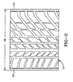
- Figure 2 is a plan view of a footprint of the tread portion of the tire of Figure 1;
- Figure 3 is an enlarged fragmentary view of the shoulder portion of the tire of Figure 1; and
- Figure 4 is an enlarged fragmentary view of the bead portion of the tire of Figure 1.
-
- "Aspect Ratio" means the ratio of a tire's section height to its section width.
- "Axial" and "axially" means the lines or directions that are parallel to the axis of rotation of the tire.
- "Bead" means that part of the tire comprising an annular tensile member wrapped by ply cords and shaped, with or without other reinforcement elements such as flippers, chippers, apexes, toe guards and chafers, to fit the design rim.
- "Belt Structure" or "Reinforcing Belts" means at least two annular layers or plies of parallel cords, woven or unwoven, underlying the tread, unanchored to the bead, and having both left and right cord angles in the range from 17° to 27° with respect to the equatorial plane of the tire.
- "Circumferential" means lines or directions extending along the perimeter of the surface of the annular tread perpendicular to the axial direction.
- "Carcass" means the tire structure apart from the belt structure, tread, undertread, and sidewall rubber over the plies, but including the beads.
- "Chafers" refers to narrow strips of material placed around the outside of the bead to protect cord plies from the rim, distribute flexing above the rim, and to seal the tire.
- "Cord" means one of the reinforcement strands of which the plies in the tire are comprised.
- "Equatorial Plane (EP)" means the plane perpendicular to the tire's axis of rotation and passing through the center of its tread.
- "Footprint" means the contact patch or area of contact of the tire tread with a flat surface at zero speed and under normal load and pressure.
- "Innerliner" means the layer or layers of elastomer or other material that form the inside surface of a tubeless tire and that contain the inflating fluid within the tire.
- "Normal Inflation Pressure" means the specific design inflation pressure and load assigned by the appropriate standards organization for the service condition for the tire.
- "Normal Load" means the specific load assigned by the appropriate standards organization for the service condition for the tire.
- "Ply" means a continuous layer of rubber-coated parallel cords.
- "Radial" and "radially" mean directions radially toward or away from the axis of rotation of the tire.
- "Radial Ply Tire" means a belted or circumferentially-restricted pneumatic tire in which the ply cords which extend from bead to bead are laid at cord angles between 65° and 90° with respect to the equatorial plane of the tire.
- "Section Height" means the radial distance from the nominal rim diameter to the outer diameter of the tire at its equatorial plane.
- "Section Width" means the maximum linear distance parallel to the axis of the tire and between the exterior of its sidewalls when and after it has been inflated at normal pressure for 24 hours, but unloaded, excluding elevations of the sidewalls due to labeling, decoration or protective bands.
- "Shoulder" means the upper portion of sidewall just below the tread edge.
- "Sidewall" means that portion of a tire between the tread and the bead.
- "Tread Width" means the arc length of the tread surface in the axial direction, that is, in a plane parallel to the axis of rotation of the tire.
- Referring to Figs. 1 and 2, there is illustrated a
tire 10 made in accordance with the present invention. In the particular embodiment illustrated, thetire 10 is a passenger tire; thetire 10 is provided with a ground-engaging tread portion 12 which terminates in theshoulder portions Sidewall portion shoulder portion bead portions 22,22' each having an annularinextensible bead core 26,26' respectively. Thetire 10 is further provided with acarcass reinforcing structure 30 which extends frombead portion 22 throughsidewall portion 18,tread portion 12,sidewall portion 20 to bead portion 22'. The turnup ends 32,34,32',34' ofcarcass reinforcing structure 30 are wrapped aboutbead cores 26,26' respectively. Thetire 10 may include a conventionalinner liner 35 forming the inner peripheral surface of thetire 10 if the tire is to be of the tubeless type. Placed circumferentially about the radially outer surface ofcarcass reinforcing structure 30 beneathtread portion 12 is a tread reinforcingbelt structure 36. In the particular embodiment illustrated,belt structure 36 comprises twocut belt plies belt plies belt ply 50 are disposed in an opposite direction to the mid-circumferential centerplane and from that of the cords ofbelt ply 51. However, thebelt structure 36 may comprise any number of belt plies of any desired configuration and the cords may be disposed at any desired angle.Belt structure 36 has a lateral stiffness across the belt width so as to minimize lifting of the tread from the road surface during operation of the tire in the uninflated state. In the embodiment illustrated, this is accomplished by making the cords ofbelt plies - The carcass reinforcing structure comprises at least two reinforcing ply structures. In the particular embodiment illustrated, there is provided a radially inner first reinforcing
ply structure 38 and a radially outer second reinforcingply structure 40, eachply structure cords 41 of reinforcingply structure tire 10. In the particular embodiment illustrated, thecords 41 are oriented at an angle of about 90 degrees with respect to the mid-circumferential centerplane CP. Thecords 41 may be made of any material normally used for cord reinforcement of rubber articles, for example, and not by way of limitation, rayon, nylon and polyester. Preferably, the cords are made of material having a high adhesion property with rubber and high heat resistance. In the particular embodiment illustrated, thecords 41 are made from rayon. The first and second reinforcingply structure - As further illustrated in Fig. 1, the first and second reinforcing
ply structure turnup ends bead core 26 and 26' respectively. The turnup ends 34,34' of thesecond ply 40 are adjacent to thebead core 26,26' and terminates radially above thebead core 26,26'. The turnup ends 32,32' of thefirst ply 38 wrap about the second ply turnup ends 34,34' and thebead core 26,26'. The turnup ends 34,34' of the first ply terminates radially a distance E above the nominal rim diameter of the tire in proximity to the radial location of the maximum section width of the tire. In the preferred embodiment, the turnup ends 34,34' are located within 20% of the section height of the tire from the radial location of the maximum section width, most preferably terminating at the radial location of the maximum section width. Alternatively, turnup ends 32,32' can terminate as described above in proximity of the radial location of the maximum section width. In such a case theturnup end 34,34' of thefirst ply 38 can be radially above or below the secondply turnup end - As further illustrated in Fig. 4, the
bead portions 22,22' of thetire 10 each have an annular substantiallyinextensible bead core 26,26' respectively. Thebead core 26,26' has aflat base surface 27,27' defined by an imaginary surface tangent to the radially innermost surfaces of the bead wires. Theflat base surface 27,27' has a pair ofedges first surface 23 extending radially fromedge 28 and an axially outersecond surface 25 extending radially fromedge 29. Thefirst surface 23 and theflat base surface 27,27' form an acute included angle α. Thesecond surface 25 and theflat base surface 27,27' form an acute included angle β. The angle α is greater than or equal to the angle β. In the preferred embodiment, α approximately equals β. - The
bead core 26,26' may further include a radiallyouter surface 31 extending between the first andsecond surfaces outer surface 31 has a maximum height H. The height H is less than the width of the base "W." The cross-section defined bysurfaces - The bead core is preferably constructed of a single or monofilament steel wire continuously wrapped. The bead construction is as described in EP-A-0590481.
- The flat base surfaces of the
bead cores 26,26' are preferably about parallel relative to the axis of rotation, while the bottom of the molded portion of the bead is inclined, the preferred inclination being approximately 5° to 10.5° relative to the axis of rotation. The inclination of the bead portion assists sealing the tire and is complimentary to the inclination of the bead seat flange of a conventional rim and is believed to assist retaining the beads seated to the rim. - Located within the
bead portions 22,22' and the radially inner portions of thesidewall portions elastomeric fillers 48 disposed betweencarcass reinforcing structure 30 and the turnup ends 32,34 and 32',34' respectively. Theelastomeric fillers 48 extend from the radially outer portion ofbead cores 26,26' respectively, up into the sidewall portion gradually decreasing in cross-sectional width. The elastomeric inserts 48 terminate a distance G from the nominal rim diameter NRD of at least 25 percent (25%) of the section height SH of the tire. In the particular embodiment illustrated, theelastomeric fillers 48 each extend radially outward from the nominal rim diameter NRD a distance of approximately forty percent (40%) of the maximum section height SH. For the purposes of this invention, the maximum section height SH of the tire shall be considered the radial distance measured from the nominal rim diameter NRD of the tire to the radially outermost part of the tread portion of the tire. Also, for the purposes of this invention, the nominal rim diameter shall be the diameter of the tire as designated by its size. - In a preferred embodiment of the invention the
bead portions 22,22' further includes at least one cord reinforcedmember bead filler 48 and the secondply turnup end 32. The cord reinforced member ormembers first end 54 and asecond end 55. Thefirst end 54 is axially and radially inward of thesecond end 55. The cord reinforced member ormembers tire 10 as a function of distance from itsfirst end 54. In the illustrated figure 4, the cord reinforced member comprises twocomponents outer component 52 has a radiallyinner end 54 that is radially above with theouter edge 29 of thebead core 26,26'. The axiallyinner component 53 has a radially inner end that is radially outward of theouter edge 29 of thebead core 26,26' by about 1 cm. The axially inner and axiallyouter components second end 55 of the cord reinforced member is located radially outward of the second ply turnup end 32 and radially inward of the termination of theturnup end 34 of thefirst ply 38. - The cords of
members cord reinforcement member members - A fabric reinforced
member 61 may be added to the bead portion of thetire 10. The fabric reinforced member has first and second ends 62,63. The member is wrapped about the first and the second plies 38,40 and thebead core 26,26'. Both the first and the second ends 62,63 extend radially above and outward of thebead core 26,26'. - The
sidewall portions elastomeric fillers 42. Thefirst fillers 42 may be employed between the innerliner and thefirst reinforcement ply 38. Thefirst fillers 42 extend from eachbead portion 22,22' radially to beneath the reinforcingbelt structure 36. Alternatively, as illustrated in the preferred embodiment of the invention as shown in figures 1,3,and 4, thesidewall portions first filler 42 and asecond filler 46. Thefirst fillers 42 are positioned as described above. Thesecond fillers 46 are located between the first and the second plies 38,40 respectively. Thesecond filler 46 extends from eachbead portion 22,22' radially outward to beneath the reinforcingbelt structure 36. - The elastomeric
first fillers 42 have a thickness B at the location of the maximum section width of thetire 10 of at least three percent (3%) of the maximum section height (SH), preferably of at least six percent (6%) and not greater than twelve percent (12%) of the maximum section height of the tire. - For purposes of this invention, the maximum section width (SW) of the tire is measured parallel to the rotational axis of the tire from the axially outer surfaces of the tire , exclusive of indicia, adornment and the like. Also, for the purposes of this invention the tread width is the axial distance across the tire perpendicular to the equatorial plane(EP) of the tire as measured from the footprint of the tire inflated to design inflation pressure,at rated load and mounted on a wheel for which it was designed. In the particular embodiment illustrated, the elastomeric
first fillers 42 each have a thickness B of approximately seven percent(7%) of the maximum section height(SH) at the maximum section width of the tire. - The elastomeric
second fillers 46 have a thickness C of at least one and one-half percent(1.5%) of the maximum section height of thetire 10 at the location of the maximum section width of the tire. In the preferred embodiment the elastomericsecond fillers 46 each have a thickness C of approximately three and one-half percent (3.5%) of the maximum section height (SH) of the tire. - The overall cross-sectional thickness of the
elastomeric fillers bead portion 22,22' to theshoulder portion - The overall sidewall thickness F in the region where it merges into the
shoulder portions - Applicants have found that by placing a reinforcing elastomeric filler between adjacent reinforcing ply structures in the manner previously described, high levels of run flat performance can be obtained. During normal operation of the tire, the inflated medium provides the necessary support to carry the load. However, when the tire is operated in the uninflated state the sidewall portions must support the entire load. The tire construction of the present invention permits efficient use of the carcass structure in the uninflated condition while also providing the desired operating performance characteristics of the tire when operated in the inflated state. When the tire is operated in the uninflated state ,deflection of the tire is only slightly greater than when operated in the inflated state. The internal surfaces of the tire do not come into contact with each other during operation in the uninflated state. Pneumatic passenger tires made in accordance with the present invention have been found to be capable of operation in the uninflated state for distances of about 100 miles (160 km) at speeds of up to 55 miles per hour (88 km/h) at 80% of the 26 psi normal rated load per Tire and Rim Association and then be returned to normal operation in the inflated state. The drivable range in the uninflated condition can be in excess of 1000 miles (1600 km).
- Performance of the tire when operated in the underinflated or uninflated condition may be enhanced by selecting a tread design which provides high lateral stability at the lateral end portions of the tread. Preferably, the tread design is as taught in EP-A-0524561.
- Run flat performance of the tire may be further enhanced by providing the ply coat of each layer of the reinforcing
ply structures elastomeric fillers fillers - In practice, the rubber compositions for the
first fillers 42,second fillers 46 and the plycoats for one ormore ply structures second fillers plies 38 and/or 40 having similar high stiffness/low hysteresis properties as hereinafter described. - Preferably, while the discussion herein refers to the plycoat(s) being for one or more of
ply structures plies - In particular, for the purposes of this invention, both of the
aforesaid fillers - The stiffness of the rubber composition for
fillers - The stiffness of the rubber composition for the ply coat for one or more of
plies - As a result, it is considered that the stiffness properties of the aforesaid rubber compositions of the first and
second fillers ply structures 38 and/or 40 cooperate with theplies 38 and/or 40 to reinforce each other and to enhance the aforesaid dimensional stability of the tire sidewalls to a greater degree than if either of the aforesaid fillers or plycoats were alone provided with a high stiffness rubber composition. - However, it is to be appreciated that rubbers with a high degree of stiffness in pneumatic tires normally be expected to generate excessive internal heat during service conditions (operating as tires on a vehicle running under load and/or without internal inflation pressure), particularly when the rubber's stiffness is achieved by a rather conventional method of simply increasing its carbon black content. Such internal heat generation within the rubber composition typically results in a temperature increase of the stiff rubber and associated tire structures which can potentially be detrimental to the useful life of the tire.
- The hysteresis of the rubber composition is a measure of its tendency to generate internal heat under service conditions. Relatively speaking, a rubber with a lower hysteresis property generates less internal heat under service conditions than an otherwise comparable rubber composition with a substantially higher hysteresis. Thus, in one aspect, a relatively low hysteresis is desired for the rubber composition for the
fillers plies - Hysteresis is a term for heat energy expended in a material (eg: cured rubber composition) by applied work and low hysteresis of a rubber composition is indicated by a relatively high rebound, a relatively low internal friction and relatively low loss modulus property values.
- Accordingly, it is important that the rubber compositions for the
fillers plies - The following selected desirable properties of the rubber compositions for the
fillers plies Properties Filler Ply Coat Hardness (Shore A) 60 - 70 60 -70 Modulus (100%) MPa 5 - 7 4 - 6 Static Compression 0.1- 0.15 0.15- 0.10 Heat Buildup (°C) <30 <30 Cold Rebound (about 23°C) 55 - 70 55 -70 E' at 100°C (MPa) 10 - 15 10 -15 E'' at 100°C (MPa) 0.5- 1.5 1 - 1.5 - The indicated hardness property is considered to be a moderate rubber hardness.
- The indicated modulus property at 100% modulus is utilized instead of a 300% modulus because the cured rubber has a relatively low ultimate elongation at its breaking point. Such a cured rubber is considered very stiff.
- The indicated static compression property, measured on a flexometer, is another indication of the relatively high stiffness of the cured rubber.
- The indicated E' property is a coefficient of the storage or elastic moduli component of the viscoelastic property which is an indication of the material (eg: cured rubber composition) stiffness.
- The indicated E" property is a coefficient of the loss or viscous moduli component of the viscoelastic property which is an indication of the hysteretic nature of the material (eg: cured rubber composition).
- The utilization of both the E' and E" properties to characterize stiffness and hysteresis of rubber compositions is well known to those having skill in such characterizations of rubber.
- The indicated heat buildup value is measured by a Goodrich flexometer (ASTM D623) test and is indicative of the internal heat generation of the material (eg: cured rubber composition).
- The indicated cold rebound test property at about 23°C (room temperature) is measured by Zwick Rebound Test (DIN 53512) test and is indicative of the material's (eg: cured rubber composition) resilience.
- Thus, the properties illustrated in Table 1 indicate a cured rubber composition with a relatively high stiffness, moderate hardness and a relatively low hysteresis for a rubber with such a high stiffness.
- The low hysteresis is demonstrated by the relatively low heat buildup, low E" and high rebound properties and is considered necessary for a rubber composition desired to have a relatively low internal heat buildup in service.
- In the compounding of the various tire components, various rubbers may be used which are, preferably, relatively high unsaturation diene-based rubbers. Representative examples of such rubbers are, although they may not be so limited, are: styrene-butadiene rubber, natural rubber, cis 1,4 and 3,4-polyisoprene rubbers, cis 1,4 and vinyl 1,2-polybutadiene rubbers, acrylonitrile-butadiene rubber, styrene-isoprene-butadiene rubber and styrene-isoprene rubber.
- Various of the preferred rubbers for the rubber compositions for the
fillers plies - Preferred combinations, or blends, of rubbers are natural cis 1,4-polyisoprene rubber and cis 1,4-polybutadiene rubber for the fillers and natural cis 1,4-polybutadiene rubber and isoprene/butadiene copolymer rubber for the plycoat(s).
- In a preferred practice, based on 100 parts by weight rubber, (A) the fillers are comprised of 60 to 100, preferably 60 to 90, parts natural rubber and, correspondingly, up to about 40, preferably 40 to 10, parts of at least one of cis 1,4 polybutadiene rubber and isoprene/butadiene rubber preferably cis 1,4-polybutadiene rubber, where said isoprene/butadiene rubber, if used, is present in a maximum of 20 parts, and (B) the said plycoat(s) are comprised of up to 100, preferably 80 to 100 and more preferably 80 to 95, parts natural rubber and, correspondingly, up to about 100, preferably up to about 20 and more preferably 20 to 5, parts of at least one of isoprene/butadiene copolymer rubber and cis 1,4 polybutadiene rubber, preferably an isoprene/butadiene rubber; wherein the ratio of isoprene to butadiene in said isoprene/butadiene copolymer rubber is in a range of 40/60 to 60/40.
- It is further contemplated, and is considered to be within the intent and scope of this invention that a small amount, such as 5 to 15 parts, of one or more organic solution polymerization prepared rubbers may be included with the aforesaid natural rubber, and cis 1,4 polybutadiene rubber and/or isoprene/butadiene rubber composition(s) for the said fillers and/or plycoat(s), of which the option and selection of such additional rubber(s) can be made by one having skill in the rubber compounding art without undue experimentation.
- Thus, in such circumstance, the description of the filler and plycoat rubbers is set forth in a "comprising" manner with the intent that small amounts of such solution polymerization prepared elastomers can be added so long as the aforesaid physical property parameters of the cured rubber compositions are met. It is considered that such rubber compounding is within the skill of those with experience in the rubber compounding art without undue experimentation.
- While not necessarily limited thereto, such other contemplated solution prepared rubbers are styrene/butadiene, and polymers of one or more of isoprene and butadiene such as 3,4-polyisoprene, styrene/isoprene/butadiene terpolymers and medium vinyl polybutadiene.
- It should readily be understood by one having skill in the art that rubber compositions for components of the pneumatic tire, including the first and
second fillers - Typical additions of carbon black comprise 30 to 100 parts by weight, of diene rubber (phr), although 40 to a maximum of 70 phr of carbon black is desirable for the high stiffness rubbers desired for the indicated fillers and plycoat(s) used in this invention. Typical amounts of resins, if used, including tackifier resins and stiffness resins, if used, including unreactive phenol formaldehyde tackifying resins and, also stiffener resins of reactive phenol formaldehyde resins and resorcinol or resorcinol and hexamethylene tetramine may collectively comprise 1 to 10 phr, with a minimum tackifier resin, if used, being 1 phr and a minimum stiffener resin, if used, being 3 phr. Such resins may sometimes be referred to as phenol formaldehyde type resins. Typical amounts of processing aids comprise 4 to 100 phr. Typical amounts of silica, if used, comprise 5 to 10 or 15 phr and amounts of silica coupling agent, if used, comprise 0.05 to 0.25 parts per part of silica, by weight. Representative silicas may be, for example, hydrated amorphous silicas. A representative coupling agent may be, for example, a bifunctional sulfur containing organo silane such as, for example, bis-(3-triethoxy-silylpropyl) tetrasulfide, bis-(3-trimethoxy-silylpropyl) tetrasulfide and bis-(3-trimethoxy-silylpropyl) tetrasulfide grafted silica from Degussa, AG. Typical amounts of antioxidants comprise 1 to 5 phr. Representative antioxidants may be, for example, diphenyl-p-phenylenediamine and others, such as those disclosed in the Vanderbilt Rubber Handbook (1978), pages 344-346. Suitable antiozonant(s) and waxes, particularly microcrystalline waxes, may be of the type shown in the Vanderbilt Rubber Handbook (1978), pages 346-347. Typical amounts of antiozonants comprise 1 to 5 phr. Typical amounts of stearic acid and/or tall oil fatty acid may comprise 1 to 3 phr. Typical amounts of zinc oxide comprise 2 up to 8 or 10 phr. Typical amounts of waxes comprise 1 to 5 phr. Typical amounts of peptizers comprise 0.1 to 1 phr. The presence and relative amounts of the above additives are not an aspect of the present invention which is primarily directed to the utilization of specified blends of resins in tire treads as sulfur vulcanizable compositions.
- The vulcanization is conducted in the presence of a sulfur vulcanizing agent. Examples of suitable sulfur vulcanizing agents include elemental sulfur (free sulfur) or sulfur donating vulcanizing agents, for example, an amine disulfide, polymeric polysulfide or sulfur olefin adducts. Preferably, the sulfur vulcanizing agent is elemental sulfur. As known to those skilled in the art, sulfur vulcanizing agents are used in an amount ranging from 0.5 to 8 phr with a range of from 3 to 5 being preferred for the stiff rubbers desired for use in this invention.
- Accelerators are used to control the time and/or temperature required for vulcanization and to improve the properties of the vulcanizate. In one embodiment, a single accelerator system may be used, i.e., primary accelerator. Conventionally, a primary accelerator is used in amounts ranging from 0.5 to 3 phr. In another embodiment, combinations of two or more accelerators in which a primary accelerator is generally used in the larger amount (0.5 to 2 phr), and a secondary accelerator which is generally used in smaller amounts (0.05-.50 phr) in order to activate and to improve the properties of the vulcanizate. Combinations of such accelerators have historically been known to produce a synergistic effect of the final properties of sulfur cured rubbers and are often somewhat better than those produced by use of either accelerator alone. In addition, delayed action accelerators may be used which are less affected by normal processing temperatures but produce satisfactory cures at ordinary vulcanization temperatures. Representative examples of accelerators include amines, disulfides, guanidines, thioureas, thiazoles, thiurams, sulfenamides, dithiocarbamates and xanthates. Preferably, the primary accelerator is a sulfenamide. If a second accelerator is used, the secondary accelerator is preferably a guanidine, dithiocarbamate or thiuram compound, although a second sulfenamide accelerator may be used. In the practice of this invention, one and sometimes two, or more accelerators are preferred for the high stiffness rubbers.
- The tire can be built, shaped, molded and cured by various methods which will be readily apparent to those having skill in the art.
- The following rubber compositions are provided which are intended to exemplary of rubber compositions with properties which can fall within those exemplified in Table 1.
- Rubber compositions are prepared and mixed by conventional rubber mixing processes and comprised of the materials shown in Table 2 which represent rubber compositions which may be contemplated for use as
fillers plies (Parts by Weight) Material Plycoat Filler Natural Rubber1 90 80 Isoprene/ Butadiene Rubber 210 0 Polybutadiene (cis 1,4-) Rubber3 0 20 Carbon black 55 55 Zinc Oxide 5 8 Accelerators (Sulfenamide type) 4 2 Sulfur (insol w/2% oil) 2 4 - Conventional amounts of rubber processing oil and tall oil fatty acid, collectively about 5 parts with a minimum of 1 part each; antidegradants; tackifying and stiffening resins, primarily of the phenolformaldehyde type in an amount of about 6 phr; and silica and coupling agent therefor; are used with two accelerators for the plycoat sample and one accelerator for the filler rubber composition sample.
- 1. Cis 1,4-polyisoprene type
- 2. Copolymer with ratio of isoprene to butadiene of about 1:1
- 3. A high cis 1,4 polybutadiene rubber
-
- The rubber compositions are molded and cured at about 150°C for about 20 minutes.
- In the practice of this invention, it is considered important that the rubber compositions for both the
fillers plies - Further, it is normally desired that the rubber composition for
fillers plies 38 and/or 40 is slightly stiffer, slightly harder and that both of the rubber compositions have a relatively low hysteresis. - It is important to appreciate that the indicated physical properties of the rubber compositions in Table 1 are for samples thereof and that the dimensions, including thickness, of the resulting tire components (fillers and plies) need be taken into account as factors contributing to the overall stiffness and dimensional stability of the tire sidewall and carcass.
- It is considered important that the stiffness of the rubber composition for
fillers - Chaffing of the tire in the lower bead region radially outward of the
carcass structure 30 adjacent the rim flange may be minimized,especially during use of the tire in the uninflated condition, by providing hardrubber chaffer portion 60,60'. - High speed performance of the tire may be enhanced by the application of a
fabric overlay layer 59 disposed about the tread reinforcingbelt structure 36. For example, two ply layers having nylon or aramid cords may be disposed about reinforcingbelt structure 36, the lateral ends of extending past the lateral ends of thebelt structure 36. Alternatively, a single layer of spirally wound aramid reinforced fabric can be employed as an overlay. The aramid material has a substantially higher modulus of elasticity than nylon and accordingly results in a stronger tire reinforcement than two layers of nylon. Applicants have found that a greater than 10% increase in high speed capability can be achieved in a tire with the single layer of spirally wound aramid overlay. Generally the use of aramid material in passenger tire applications is avoided due in part to the fact that the material exhibits poor noise properties that resonate sounds through the relatively thin sidewalls of the passenger tire. Applicants' tire of the present invention employs thick sidewalls which noticeably dampen tire generated noises. The noise dampening sidewalls permit the use of an aramid overlay without experiencing unacceptable noise levels. - In the illustrated preferred embodiment, the aramid reinforced fabric is wound circumferentially about the reinforcing belt layers overlapping the belt edges. The
overlay fabric 59 is wrapped in approximately 2.5 cm (1.0 inch) wide strips which are abutted. Alternatively, each strip may overlap the adjacent wound strips. Preferably the strips overlap in the range of 25% to 100% of the strip width. At the axial extremes of the overlay, the strips may include multiple winding for added strength at these highly stressed areas.
Claims (11)
- A radial ply pneumatic tire (10) having an axis of rotation, a tread (12) having a pair of lateral edges,a belt structure (36) located radially inward of the tread, a pair of sidewalls (18,20), one sidewall extending radially inwardly from each lateral edge, a maximum section width (SW), and a tire carcass structure, the tire carcass structure comprises:characterised by a pair of first fillers (42), a pair of second fillers (46), the first fillers each being between the first ply structure (38) and the innerliner, one first filler extending from each bead portion (22,22') radially outward to beneath the reinforcing belts, the second fillers (46) being between the first and second ply structure, one second filler extending from each bead portion radially outward to beneath the reinforcing belt; anda) a pair of bead portions (22,22'), one bead portion extending radially inwardly from each sidewall, each portion including a substantially inextensible core (26,26');b) a carcass reinforcing structure (30) radially inward of the reinforcing belt structure (36) extending circumferentially about the tire from one bead portion to the other bead portion, the carcass reinforcing structure having a first ply structure (38) and a second ply structure (40) provided with an elastomeric ply coat, the first ply structure having a pair of turnup ends (34,34'), wrapped about each bead core (26,26'), extending axially and radially outwardly, and terminating radially in proximity to the radial location of the maximum section width of the tire;c) an inner liner (35) radially inward of the first ply structure (38);d) a bead filler (48) located above each bead core (26,26') and between the second ply structure (40) and the turnup ends (32,34;32',34') of the first and second ply structures;
wherein, based on 100 parts by weight rubber, the fillers (42,46) are comprised of 60 to 100 parts natural cis 1,4-polyisoprene rubber and, correspondingly, up to 40 parts of at least one of cis 1,4-polybutadiene rubber and isoprene/butadiene rubber and 40 to 70 phr carbon black and 5 to 15 phr silica, if used. - The tire of claim 1 wherein the plycoat(s) are comprised of up to 100 parts natural cis 1,4-polyisoprene rubber and, correspondingly, up to 100 parts of at least one of isoprene/butadiene copolymer rubber and cis 1,4-polybutadiene rubber; wherein the ratio of isoprene to butadiene in said isoprene/butadiene copolymer is in a range of 30/70 to 60/40 and 40 to 70 phr carbon black and 5 to 15 phr silica, if used.
- The tire of claim 1 or 2 wherein, based on 100 parts by weight rubber, the fillers (42,46) are comprised of 60 to 90 parts natural rubber and, correspondingly, 10 to 40 parts of at least one of cis 1,4-polybutadiene and isoprene/butadiene copolymer rubber.
- The tire of claim 2 wherein, based on 100 parts by weight rubber, the plycoat(s) are comprised of 80 to 100 parts natural rubber and, correspondingly, up to 20 parts isoprene/butadiene copolymer rubber.
- The tire of claim 2 wherein, based on 100 parts by weight rubber, the plycoat(s) are comprised of 80 to 95 parts natural rubber and, correspondingly, 20 to 5 parts of at least one of isoprene/butadiene copolymer rubber and cis 1,4-polybutadiene rubber.
- The tire of claim 1 wherein the filler (42,46) is comprised of 60 to 90 parts natural rubber and cis 1,4-polybutadiene rubber and the plycoat(s) are comprised of 80 to 95 parts natural rubber and 20 to 5 parts isoprene/butadiene copolymer rubber.
- The tire of claim 3 wherein the first ply structure and second ply (38,40) of the carcass reinforcing structure have an elastomeric ply coat having material properties substantially similar to the first and second fillers (42,46).
- The tire of claim 7 wherein the first and second fillers (42,46) have material properties E' and E'' both at 100 degrees C (MPA), E' being in the range of 10-15 and E'' being in the range of 0.5-1.5.
- The tire of claim 1 further comprising a fabric reinforced member (61) integral of the bead portion (22,22'), the fabric reinforced member having first and second ends (62,63) the member being wrapped about the first and second ply structures (38,40) and the bead core (26,26'), both the first and second ends radially extending above the bead core.
- The tire of claim 1 characterized in that each ply structure (38,40) comprises a single ply layer.
- The tire of claim 1 characterized in that the turnup ends (34,34') are located within 20% of the section height of the tire from the radial location of the maximum section width.
Applications Claiming Priority (3)
| Application Number | Priority Date | Filing Date | Title |
|---|---|---|---|
| US08/954,209 US5368082A (en) | 1992-09-30 | 1992-09-30 | Radial ply pneumatic tire |
| EP93115227A EP0590482B1 (en) | 1992-09-30 | 1993-09-22 | A radial ply pneumatic tire |
| US954209 | 1997-10-20 |
Related Parent Applications (2)
| Application Number | Title | Priority Date | Filing Date |
|---|---|---|---|
| EP93115227.6 Division | 1993-09-22 | ||
| EP93115227A Division EP0590482B1 (en) | 1992-09-30 | 1993-09-22 | A radial ply pneumatic tire |
Publications (3)
| Publication Number | Publication Date |
|---|---|
| EP0787603A2 EP0787603A2 (en) | 1997-08-06 |
| EP0787603A3 EP0787603A3 (en) | 1999-05-19 |
| EP0787603B1 true EP0787603B1 (en) | 2003-03-19 |
Family
ID=25495091
Family Applications (2)
| Application Number | Title | Priority Date | Filing Date |
|---|---|---|---|
| EP97107255A Expired - Lifetime EP0787603B1 (en) | 1992-09-30 | 1993-09-22 | A radial ply pneumatic tire |
| EP93115227A Expired - Lifetime EP0590482B1 (en) | 1992-09-30 | 1993-09-22 | A radial ply pneumatic tire |
Family Applications After (1)
| Application Number | Title | Priority Date | Filing Date |
|---|---|---|---|
| EP93115227A Expired - Lifetime EP0590482B1 (en) | 1992-09-30 | 1993-09-22 | A radial ply pneumatic tire |
Country Status (9)
| Country | Link |
|---|---|
| US (4) | US5368082A (en) |
| EP (2) | EP0787603B1 (en) |
| JP (1) | JP3372311B2 (en) |
| KR (1) | KR100284471B1 (en) |
| AU (3) | AU670119B2 (en) |
| BR (1) | BR9303836A (en) |
| CA (1) | CA2088382C (en) |
| DE (2) | DE69315654T2 (en) |
| MX (1) | MX9305781A (en) |
Families Citing this family (122)
| Publication number | Priority date | Publication date | Assignee | Title |
|---|---|---|---|---|
| US5685927A (en) | 1992-09-30 | 1997-11-11 | The Goodyear Tire & Rubber Company | Run-flat tire with wet handling design |
| US5263526A (en) * | 1992-09-30 | 1993-11-23 | The Goodyear Tire & Rubber Company | Pneumatic tire having specified bead structure |
| EP0637519B1 (en) * | 1993-08-06 | 1997-10-15 | Sedepro | Tyre having a bead with a specific shape |
| US5427166A (en) * | 1994-01-18 | 1995-06-27 | Michelin Recherche Et Technique S.A. | Run-flat tire with three carcass layers |
| US5725701A (en) * | 1996-03-13 | 1998-03-10 | The Goodyear Tire & Rubber Company | Low pressure all terrain vehicle tire |
| US5879482A (en) * | 1996-03-15 | 1999-03-09 | Goodyear Tire & Rubber Company | Run-flat low-pressure all terrain vehicle (ATV) tire |
| EP0810105B1 (en) * | 1996-05-29 | 2003-07-09 | Bridgestone Corporation | Pneumatic radial tires provided with a side portion reinforcing layer |
| US5795416A (en) * | 1996-08-02 | 1998-08-18 | Michelin Recherche Et Technique | Run-flat tire having partial carcass layers |
| US5769980A (en) * | 1996-11-13 | 1998-06-23 | Bridgestone/Firestone, Inc. | Pneumatic tire with sidewall inserts having specified extension underneath the belt package |
| US5879484A (en) * | 1997-01-13 | 1999-03-09 | Bridgestone/Firestone, Inc. | Run flat banded pneumatic tire |
| US6422280B1 (en) | 1997-01-30 | 2002-07-23 | The Goodyear Tire & Rubber Company | Heavy duty tire with specified bead design |
| US5871602A (en) * | 1997-05-29 | 1999-02-16 | The Goodyear Tire & Rubber Company | Tire with carcass turn up ends under belt structure |
| US5871600A (en) * | 1997-05-29 | 1999-02-16 | The Goodyear Tire & Rubber Company | Runflat tire with different modulus or elongation carcass cords |
| BR9809698A (en) * | 1997-05-29 | 2000-07-11 | Goodyaer Tire & Rubber Company | Tire with composite canvas structure and manufacturing method |
| US6026878A (en) * | 1997-05-29 | 2000-02-22 | The Goodyear Tire & Rubber Company | Inextensible high temperature resistant tire |
| KR100582331B1 (en) * | 1997-05-29 | 2006-05-23 | 더 굿이어 타이어 앤드 러버 캄파니 | Tire with composite ply structure and method of manufacture |
| US6082423A (en) * | 1997-06-09 | 2000-07-04 | The Goodyear Tire & Rubber Company | Low cost light weight radial tire |
| US6016858A (en) * | 1997-06-09 | 2000-01-25 | The Goodyear Tire & Rubber Company | Light weight fiberglass belted radial tire |
| US6016857A (en) * | 1997-06-09 | 2000-01-25 | The Goodyear Tire & Rubber Company | Light weight aramid radial tire |
| US5868190A (en) * | 1997-06-10 | 1999-02-09 | Michelin Recherche Et Technique, S.A. | Run-flat tire with an improved bead to rim interface |
| US6142205A (en) * | 1998-03-13 | 2000-11-07 | The Goodyear Tire & Rubber Company | Tire with composite ply structure |
| US6230773B1 (en) * | 1998-03-17 | 2001-05-15 | The Goodyear Tire & Rubber Company | Tire with sidewall carcass reinforcement |
| US6338374B1 (en) | 1998-03-26 | 2002-01-15 | The Goodyear Tire & Rubber Company | Runflat tire with fabric underlay and tread insert |
| US6068721A (en) * | 1998-03-27 | 2000-05-30 | The Goodyear Tire & Rubber Company | Method of fabricating a tire having a geodesic ply |
| US6117258A (en) * | 1998-04-27 | 2000-09-12 | Bridgestone/Firestone Research, Inc. | Band element and method for building same for a run flat banded tire |
| US7260371B1 (en) | 1998-04-14 | 2007-08-21 | The Goodyear Tire & Rubber Company | Programmable modulation index for transponder |
| US6922134B1 (en) | 1998-04-14 | 2005-07-26 | The Goodyear Tire Rubber Company | Programmable trimmer for transponder |
| US6358346B1 (en) | 2000-07-28 | 2002-03-19 | The Goodyear Tire & Rubber Company | Method of building tire with composite ply structure |
| US6550509B1 (en) | 1998-06-19 | 2003-04-22 | The Goodyear Rubber & Tire Company | Tread and sidewall construction for runflat tire |
| US6631748B1 (en) | 1998-07-06 | 2003-10-14 | The Goodyear Tire & Rubber Company | Sidewall with insert construction for runflat tire |
| US6561245B1 (en) | 1998-07-10 | 2003-05-13 | The Goodyear Tire & Rubber Company | Thread reinforcement means for extended mobility tire |
| US6148885A (en) | 1998-07-21 | 2000-11-21 | Bridgestone/Firestone Research, Inc. | Pneumatic tire with band element |
| WO2000007834A2 (en) | 1998-08-03 | 2000-02-17 | The Goodyear Tire & Rubber Company | Mounting transponders in pneumatic tires |
| BR9903977A (en) | 1998-09-09 | 2000-10-10 | Goodyear Tire & Rubber | Flat operating tire |
| CA2282027A1 (en) * | 1998-09-25 | 2000-03-25 | Thomas Paul Wolski | Antireversion agent for inserts used in runflat tires |
| DE19845724A1 (en) | 1998-10-05 | 2000-04-06 | Dunlop Gmbh | Pneumatic vehicle tires |
| DE19846854A1 (en) | 1998-10-12 | 2000-04-20 | Dunlop Gmbh | Pneumatic tire, used as a vehicle safety tire, has sidewall rubber reinforcement layers of different heights and varying thicknesses |
| US6536495B1 (en) | 1998-11-02 | 2003-03-25 | The Goodyear Tire & Rubber Company | Tread stiffening for two ply runflat tire |
| EP1524132B1 (en) * | 1998-12-17 | 2012-04-18 | Bridgestone Corporation | Pneumatic tire |
| DE69923759T2 (en) * | 1998-12-21 | 2006-05-11 | Bridgestone Corp. | Radial pneumatic tire |
| DE19860362A1 (en) * | 1998-12-24 | 2000-06-29 | Dunlop Gmbh | Pneumatic vehicle tires |
| DE69907127T2 (en) * | 1999-01-20 | 2004-02-12 | The Goodyear Tire & Rubber Co., Akron | Tires with an improved run-flat structure |
| US6763866B1 (en) | 1999-02-03 | 2004-07-20 | The Goodyear Tire & Rubber Company | Reinforced wedge-insert construction for extended mobility tires |
| US6712108B1 (en) | 1999-02-05 | 2004-03-30 | The Goodyear Tire & Rubber Company | Discontinuous ply for runflat tire construction |
| US6980084B1 (en) | 1999-05-17 | 2005-12-27 | The Goodyear Tire & Rubber Company | Power-on reset for transponder |
| US6995672B1 (en) | 1999-05-17 | 2006-02-07 | The Goodyear Tire & Rubber Co. | Relaxation oscillator for transponder |
| DE69908661T2 (en) | 1999-05-17 | 2004-04-29 | The Goodyear Tire & Rubber Co., Akron | RF TRANSPONDER WITH A RELAXATION OSCILLATOR AND METHOD FOR GENERATING AN OSCILLATING MEASURING SIGNAL IN AN RF TRANSPONDER |
| US6695025B1 (en) | 1999-05-18 | 2004-02-24 | The Goodyear Tire & Rubber Company | Runflat tire construction with ply cords having a variable modulus of elasticity |
| US6494242B2 (en) | 1999-05-27 | 2002-12-17 | Michelin Recherche Et Technique | Runflat tire having optimized carcass path |
| CA2338573A1 (en) * | 1999-05-27 | 2000-12-07 | Roger Cary Cottrell | Runflat tire having optimized carcass path |
| US6182728B1 (en) | 1999-06-04 | 2001-02-06 | Hankook Tire | Pneumatic run flat tire |
| WO2001002195A1 (en) | 1999-07-01 | 2001-01-11 | The Goodyear Tire & Rubber Company | Fabric support for metal reinforced inner ply of runflat tire |
| US6809637B1 (en) | 1999-09-03 | 2004-10-26 | The Goodyear Tire & Rubber Company | Monitoring a condition of a pneumatic tire |
| JP2003508299A (en) | 1999-09-03 | 2003-03-04 | ザ・グッドイヤー・タイヤ・アンド・ラバー・カンパニー | How to monitor the condition of pneumatic tires |
| WO2001019626A1 (en) | 1999-09-15 | 2001-03-22 | The Goodyear Tire & Rubber Company | Low pressure warning system (lpws) for pneumatic tires |
| US6581449B1 (en) | 1999-09-15 | 2003-06-24 | The Goodyear Tire & Rubber Company | Low pressure warning system for pneumatic tires with RF tags and monitors for each tire |
| US6923233B1 (en) | 1999-09-30 | 2005-08-02 | The Goodyear Tire & Rubber Company | Runflat tire with sawtooth shaped insert |
| WO2001025032A1 (en) * | 1999-09-30 | 2001-04-12 | The Goodyear Tire & Rubber Company | Runflat tire with sawtooth shaped insert |
| US6899153B1 (en) | 1999-11-15 | 2005-05-31 | The Goodyear Tire & Rubber Company | Mounting transponders and antennas in pneumatic tires |
| US6885291B1 (en) | 1999-11-15 | 2005-04-26 | The Goodyear Tire & Rubber Company | Mouting transponders and antennas in pneumatic tires |
| WO2001043994A1 (en) | 1999-12-14 | 2001-06-21 | The Goodyear Tire & Rubber Company | Tire with compression-bearing hoop structure |
| AU2844300A (en) | 1999-12-14 | 2001-06-25 | Goodyear Tire And Rubber Company, The | Method of monitoring pressure in a pneumatic tire |
| US6843293B1 (en) | 1999-12-16 | 2005-01-18 | The Goodyear Tire & Rubber Company | Variable-stiffness wedge insert for runflat tires |
| US6386258B1 (en) | 2000-02-10 | 2002-05-14 | The Goodyear Tire & Rubber Company | Tire having a geodesic ply and a method of fabricating |
| US6476110B1 (en) * | 2000-02-18 | 2002-11-05 | Continental Ag | Rubber composition containing solid magnetizable particles of greater stiffness than the rubbery compounds |
| JP2001239813A (en) * | 2000-02-29 | 2001-09-04 | Bridgestone Corp | Pneumatic tire |
| US6460586B1 (en) | 2000-03-29 | 2002-10-08 | Bridgestone/Firestone North American Tire, Llc | Multi-region band element for run flat tire |
| US6321808B1 (en) | 2000-03-29 | 2001-11-27 | Bridgestone/Firestone Research, Inc. | Expandable band for run flat tire and method of making |
| JP2003528761A (en) * | 2000-03-31 | 2003-09-30 | ピレリ・プネウマティチ・ソチエタ・ペル・アツィオーニ | Automotive self-supporting tire and method for manufacturing the same |
| US6401777B1 (en) * | 2000-04-10 | 2002-06-11 | The Goodyear Tire & Rubber Company | Tire chipper construction for runflat tires |
| US6453961B1 (en) | 2000-06-01 | 2002-09-24 | The Goodyear Tire & Rubber Company | Variable-stiffness wedge insert for runflat tire |
| US6405773B1 (en) | 2000-06-14 | 2002-06-18 | Bridgestone/Firestone North American Tire, Llc | Run flat pneumatic tire and band element therefor |
| US6834696B1 (en) | 2000-06-29 | 2004-12-28 | Bridgestone/Firestone North American Tire, Llc | Runflat tire with cantilever-like sidewall construction |
| JP4053719B2 (en) * | 2000-09-08 | 2008-02-27 | 住友ゴム工業株式会社 | Tires with improved run flatness |
| US6470937B1 (en) | 2000-10-03 | 2002-10-29 | Bridgestone/Firestone North American Tire, Llc | Run flat pneumatic tire and anticlastic band element therefor |
| US6439288B1 (en) | 2000-11-28 | 2002-08-27 | Bridgestone/Firestone North American Tire, Llc | Pneumatic tire with variable thickness band element |
| US6435239B1 (en) | 2000-11-30 | 2002-08-20 | Bridgestone/Firestone North American Tire, Llc | Pneumatic tire having multiple element bead assembly |
| US6894600B2 (en) * | 2001-07-05 | 2005-05-17 | The Goodyear Tire & Rubber Company | Energy conservation in battery powered tag |
| US6606902B2 (en) * | 2001-07-09 | 2003-08-19 | The Goodyear Tire & Rubber Company | Method of improving steering performance robustness utilizing stiffness non-uniformity in tire/wheel |
| US6668635B2 (en) * | 2001-07-09 | 2003-12-30 | The Goodyear Tire & Rubber Company | Method of improving steering performance robustness utilizing dimensional non-uniformity in tire/wheel |
| US6672148B2 (en) | 2001-07-09 | 2004-01-06 | The Goodyear Tire & Rubber Company | Method of improving steering performance robustness utilizing mass non-uniformity in tire/wheel |
| EP1465947A4 (en) * | 2001-12-13 | 2005-11-30 | Exxonmobil Chem Patents Inc | Thermoplastic vulcaninates for run-flat tires |
| ES2316760T3 (en) * | 2002-06-05 | 2009-04-16 | Bridgestone Corporation | PROCEDURE TO PRODUCE A TIRE. |
| US6719029B2 (en) * | 2002-08-09 | 2004-04-13 | The Goodyear Tire & Rubber Company | Tire wall gauges to optimize runflat tire ride comfort |
| US6938659B2 (en) * | 2002-09-19 | 2005-09-06 | The Goodyear Tire & Rubber Company | Runflat tire having crown-reinforcing insert extending into the sidewalls |
| US20060128907A1 (en) * | 2002-12-12 | 2006-06-15 | Yu Thomas C | Process for making a thermoplastic vulcanizates |
| US6988522B2 (en) * | 2002-12-12 | 2006-01-24 | The Goodyear Tire & Rubber Company | Self-supporting pneumatic tire with a partial inner liner |
| US20040261928A1 (en) * | 2003-06-27 | 2004-12-30 | Imhoff Serge Julien Auguste | Polyester cords and their use in runflat tires |
| JP2005119384A (en) * | 2003-10-15 | 2005-05-12 | Bridgestone Corp | Run flat tire |
| US7086440B2 (en) * | 2003-11-14 | 2006-08-08 | The Goodyear Tire & Rubber Company | Pneumatic tire with annular reinforcing strip layer |
| JP2005161998A (en) * | 2003-12-02 | 2005-06-23 | Bridgestone Corp | Pneumatic tire |
| JP4744800B2 (en) * | 2003-12-05 | 2011-08-10 | 株式会社ブリヂストン | Pneumatic tire |
| FR2864469A1 (en) * | 2003-12-30 | 2005-07-01 | Michelin Soc Tech | Pneumatic tyre designed to run when deflated has self-supporting side walls reinforced by inserts of rigid rubber composition in zones |
| BRPI0406207A (en) * | 2004-04-22 | 2006-02-21 | Goodyear Tire & Rubber | empty wheel tire |
| US7255146B2 (en) * | 2004-09-13 | 2007-08-14 | Bridgestone Firestone North American Tire, Llc | Apparatus and method of enhancing run-flat travel for pneumatic tires |
| US7389802B2 (en) * | 2004-12-30 | 2008-06-24 | The Goodyear Tire & Rubber Co. | Tire with double layer innerliner |
| EP1676730B1 (en) * | 2004-12-31 | 2008-04-16 | Societe de Technologie Michelin STM | Extended mobility tire having separated carcass portions in summit |
| US8631844B2 (en) | 2005-06-13 | 2014-01-21 | Millenworks | Variable compliance wheel |
| EP1733901A1 (en) * | 2005-06-16 | 2006-12-20 | Societe de Technologie Michelin | Extended-mobility tire having separated carcass portions in summit |
| US7509987B2 (en) * | 2005-11-22 | 2009-03-31 | The Goodyear Tire & Rubber Company | Tire with turned down ply construction |
| JP4703384B2 (en) * | 2005-11-30 | 2011-06-15 | 株式会社ブリヂストン | Run flat tire |
| JP4948842B2 (en) * | 2006-01-30 | 2012-06-06 | 株式会社ブリヂストン | Pneumatic tire |
| JP2008049966A (en) * | 2006-08-28 | 2008-03-06 | Bridgestone Corp | Pneumatic tire |
| JP5228052B2 (en) * | 2007-09-27 | 2013-07-03 | ピレリ・タイヤ・ソチエタ・ペル・アツィオーニ | Method and plant for manufacturing tires for vehicle wheels |
| US20090095397A1 (en) * | 2007-10-15 | 2009-04-16 | Robert Anthony Neubauer | Floating two-ply tire |
| US8056596B2 (en) * | 2007-10-22 | 2011-11-15 | The Goodyear Tire + Rubber Company, Inc. | Multiple ply modular construction |
| JP5530059B2 (en) * | 2007-10-30 | 2014-06-25 | 株式会社ブリヂストン | Pneumatic tire |
| US20090277554A1 (en) * | 2008-05-06 | 2009-11-12 | Yves Donckels | High twist polyester carcass ply for a pneumatic tire |
| US8037913B2 (en) * | 2008-08-19 | 2011-10-18 | The Goodyear Tire & Rubber Company | Pneumatic tire with single non-continuous carcass ply |
| US20100051164A1 (en) | 2008-08-29 | 2010-03-04 | Robert Anthony Neubauer | Modular ply tire with dissimilar materials |
| US20100051162A1 (en) | 2008-08-29 | 2010-03-04 | Robert Anthony Neubauer | Modular two-ply tire with directional side plies |
| US8205652B2 (en) * | 2008-12-12 | 2012-06-26 | The Goodyear Tire & Rubber Company | Self-supporting pneumatic tire with optimized ply line |
| US20100147433A1 (en) * | 2008-12-12 | 2010-06-17 | Thierry Paul-Marie Gabriel Koeune | Self-supporting pneumatic tire |
| US20110146871A1 (en) | 2009-12-23 | 2011-06-23 | Richard Frank Laske | Self-supporting pneumatic tire |
| FR2977828B1 (en) * | 2011-07-13 | 2013-08-16 | Michelin Soc Tech | PNEUMATIC FOLDING MACHINE, FOLDING METHOD AND USE |
| JP5905112B2 (en) | 2011-10-24 | 2016-04-20 | ブリヂストン アメリカズ タイヤ オペレイションズ エルエルシー | Silica-filled rubber composition and method for producing the same |
| WO2015156975A1 (en) * | 2014-04-07 | 2015-10-15 | Bridgestone Americas Tire Operations, Llc | Tire with pre-stressed toroidal element |
| JP6972975B2 (en) * | 2017-11-29 | 2021-11-24 | 横浜ゴム株式会社 | Pneumatic tires |
| CN111542441B (en) * | 2017-12-22 | 2022-05-06 | 横滨橡胶株式会社 | Runflat tire |
| JP6720997B2 (en) * | 2018-04-10 | 2020-07-08 | 横浜ゴム株式会社 | Run flat tires |
| USD986810S1 (en) | 2021-08-16 | 2023-05-23 | Bridgestone Americas Tire Operations, Llc | Tire |
| USD986811S1 (en) | 2021-08-16 | 2023-05-23 | Bridgestone Americas Tire Operations, Llc | Tire |
Family Cites Families (74)
| Publication number | Priority date | Publication date | Assignee | Title |
|---|---|---|---|---|
| US1393952A (en) * | 1921-10-18 | Tire-casing | ||
| US1294161A (en) * | 1917-12-10 | 1919-02-11 | Alphonso Comstock Pratt | Gromet. |
| US1437013A (en) * | 1919-03-25 | 1922-11-28 | Internat Bead Wire Company | Grommet or core for tire beads |
| GB152843A (en) * | 1919-09-13 | 1920-10-28 | Max John Railing | Improvements in electric lamp fittings |
| US2430560A (en) * | 1942-12-30 | 1947-11-11 | Goodrich Co B F | Tire |
| BE569490A (en) * | 1957-09-18 | |||
| FR1355014A (en) * | 1963-02-01 | 1964-03-13 | Mft Fr Pneumatiques Michelin | Improvements to tire casings |
| FR1448109A (en) * | 1965-06-01 | 1966-08-05 | Fr Du Pneu Englebert Soc | Oriented drift pneumatic jacket |
| US3386486A (en) * | 1965-10-22 | 1968-06-04 | Goodyear Tire & Rubber | Tires |
| DE1605616A1 (en) * | 1966-06-15 | 1971-03-11 | Continental Gummi Werke Ag | Pneumatic vehicle tires |
| US3542108A (en) * | 1968-05-23 | 1970-11-24 | Goodyear Tire & Rubber | Tire |
| FR2076641A5 (en) * | 1970-01-21 | 1971-10-15 | Michelin & Cie | |
| US3682223A (en) * | 1970-05-20 | 1972-08-08 | Goodyear Tire & Rubber | Tire bead construction |
| AU4484972A (en) * | 1971-07-23 | 1974-01-24 | Toyo Tire & Rubber Co | Radial-ply tire |
| DE2202944C3 (en) * | 1972-01-21 | 1982-10-07 | Dunlop Ag, 6450 Hanau | Pneumatic vehicle tires |
| DE2204746A1 (en) * | 1972-02-01 | 1973-08-09 | Uniroyal Ag | TUBELESS VEHICLE TIRE |
| DE2229888A1 (en) * | 1972-06-19 | 1974-01-10 | Dunlop Ag | STEEL BELT FOR VEHICLE TIRES |
| GB1436725A (en) * | 1972-06-21 | 1976-05-26 | Bridgestone Tire Co Ltd | Pneumatic safety tyre |
| JPS5249603B2 (en) * | 1972-11-13 | 1977-12-19 | ||
| JPS5235161B2 (en) * | 1973-06-21 | 1977-09-07 | ||
| GB1487997A (en) * | 1973-10-20 | 1977-10-05 | Dunlop Ltd | Pneumatic tyres |
| GB1491197A (en) * | 1973-11-07 | 1977-11-09 | Dunlop Ltd | Pneumatic tyres |
| US3961657A (en) * | 1974-05-03 | 1976-06-08 | The Goodyear Tire & Rubber Company | High speed radial ply tire |
| US3946785A (en) * | 1974-08-01 | 1976-03-30 | The Firestone Tire & Rubber Company | Simplified bead construction for pneumatic tires |
| US3983919A (en) * | 1974-10-09 | 1976-10-05 | The B. F. Goodrich Company | High-modulus rubber composition for pneumatic tires |
| CA1051330A (en) * | 1974-10-09 | 1979-03-27 | John T. Alden | Pneumatic tire |
| US4142567A (en) * | 1975-08-06 | 1979-03-06 | Continental Gummi-Werke Aktiengesellschaft | Pneumatic vehicle tire |
| JPS5237303A (en) * | 1975-09-18 | 1977-03-23 | Bridgestone Corp | Light air tire having thin side wall rubber and method of fabricating the same |
| JPS53138106A (en) * | 1976-10-02 | 1978-12-02 | Toyo Tire & Rubber Co Ltd | Pneumatic safety tire |
| IT1072537B (en) * | 1976-10-05 | 1985-04-10 | Sarda Off Mecc Spa | IMPROVEMENT TO RADIAL TIRES PROVIDED WITH STRUCTURE FOR STRENGTHENING THE SIDES |
| IT1065465B (en) * | 1976-12-20 | 1985-02-25 | Pirelli | REFERENCES TO HEELS OF RADIAL TIRES |
| DE7713948U1 (en) * | 1977-05-03 | 1977-09-29 | Uniroyal Ag, 5100 Aachen | HEAVY-DUTY VEHICLE TIRES, MOUNTED ON ANGLE SHOULDER RIMS, WITH A RING-SHAPED REINFORCEMENT UNIT FOR THE Bead |
| US4405007A (en) * | 1977-06-27 | 1983-09-20 | The Goodyear Tire & Rubber Company | Pneumatic safety tire |
| JPS5427104A (en) * | 1977-08-01 | 1979-03-01 | Yokohama Rubber Co Ltd:The | Run-flat tire for use in two-wheel car |
| US4193437A (en) * | 1977-09-16 | 1980-03-18 | The B. F. Goodrich Company | Self supporting tire |
| FR2425333A1 (en) * | 1978-05-10 | 1979-12-07 | Kleber Colombes | SAFETY TIRES |
| JPS5534001A (en) * | 1978-08-28 | 1980-03-10 | Noda Sangyo Kagaku Kenkyusho | Stabilization of sarcosine oxidase |
| JPS5559005A (en) * | 1978-10-30 | 1980-05-02 | Bridgestone Corp | Air-filled safety tire |
| JPS5568406A (en) * | 1978-11-20 | 1980-05-23 | Bridgestone Corp | Air-filled safety tire with effective puncture-proof drivability |
| CA1126635A (en) * | 1979-06-06 | 1982-06-29 | Mark H. Mineur | Pneumatic safety tire |
| JPS5718503A (en) * | 1980-07-08 | 1982-01-30 | Bridgestone Corp | Pneumatic radial tire excellent in stability of steering |
| ZA817371B (en) * | 1980-11-24 | 1982-10-27 | Goodyear Tire & Rubber | A pneumatic safety tire |
| JPS57151406A (en) * | 1981-03-14 | 1982-09-18 | Sumitomo Rubber Ind Ltd | Tyre having improved bead |
| JPS5822704A (en) * | 1981-08-04 | 1983-02-10 | Bridgestone Corp | Pneumatic semiradial tire for motorcycle |
| JPS58185304A (en) * | 1982-04-23 | 1983-10-29 | Bridgestone Corp | Pneumatic tire for motorcycle |
| IT1160797B (en) * | 1983-04-18 | 1987-03-11 | Pirelli | SELF-SUPPORTING TIRE |
| US5435370A (en) * | 1985-05-08 | 1995-07-25 | Uniroyal Goodrich Licensing Services, Inc. | Pneumatic tire having discontinuous outer carcass ply |
| JPS62255205A (en) * | 1986-04-30 | 1987-11-07 | Bridgestone Corp | Pneumatic safety tire |
| JP2599164B2 (en) * | 1986-05-16 | 1997-04-09 | 住友ゴム工業 株式会社 | Radial tires for four-wheeled vehicles |
| JPH06102406B2 (en) * | 1986-05-28 | 1994-12-14 | 株式会社ブリヂストン | Pneumatic safety tires |
| JPS63315304A (en) * | 1987-06-17 | 1988-12-23 | Bridgestone Corp | Pneumatic radial tire for aircraft |
| EP0319588B2 (en) * | 1987-06-18 | 1998-02-04 | Sumitomo Rubber Industries Limited | Pneumatic radial tire and production thereof |
| US5205883A (en) * | 1988-02-23 | 1993-04-27 | The Yokohama Rubber Co., Ltd. | Pneumatic tire with polygonal bead core |
| JPH01223004A (en) * | 1988-03-01 | 1989-09-06 | Bridgestone Corp | Pneumatic tyre for high internal pressure and heavy load |
| US4869307A (en) * | 1988-03-17 | 1989-09-26 | The Goodyear Tire & Rubber Company | Pneumatic tire and method for making same |
| JP2918229B2 (en) * | 1988-05-30 | 1999-07-12 | オーツタイヤ株式会社 | Radial tire |
| JPH0237003A (en) * | 1988-07-28 | 1990-02-07 | Yokohama Rubber Co Ltd:The | Heavy load tubeless tyre |
| JPH02147417A (en) * | 1988-11-30 | 1990-06-06 | Sumitomo Rubber Ind Ltd | Pneumatic safety tire |
| JPH02241807A (en) * | 1989-03-15 | 1990-09-26 | Bridgestone Corp | Pneumatic radial tire for passenger car |
| US4989658A (en) * | 1989-06-09 | 1991-02-05 | The Goodyear Tire & Rubber Company | Belt overlay structure for pneumatic tires comprising a single ribbon wrapped about the belt structure |
| CA2018018C (en) * | 1989-08-10 | 1999-10-05 | Rene Francois Reuter | Pneumatic tire |
| JP2913322B2 (en) * | 1989-09-08 | 1999-06-28 | 横浜ゴム株式会社 | Runflat pneumatic radial tires |
| JPH0415111A (en) * | 1990-05-07 | 1992-01-20 | Sumitomo Rubber Ind Ltd | Safety tire |
| JPH0459403A (en) * | 1990-06-28 | 1992-02-26 | Yokohama Rubber Co Ltd:The | Run-flat pneumatic radial tire |
| DE4021450A1 (en) * | 1990-07-05 | 1992-01-09 | Uniroyal Englebert Gmbh | VEHICLE TIRES |
| IT1245271B (en) * | 1990-09-14 | 1994-09-13 | Pirelli | SELF-SUPPORTING CARCASS FOR MOTOR VEHICLE TIRES |
| US5223061A (en) * | 1990-10-01 | 1993-06-29 | The Goodyear Tire & Rubber Company | Belt structure for a radial pneumatic tire, including spirally wound strips reinforced by cords comprising aramid yarns |
| JP2870703B2 (en) * | 1990-11-28 | 1999-03-17 | 住友ゴム工業 株式会社 | Pneumatic tire |
| JPH04221209A (en) * | 1990-12-21 | 1992-08-11 | Bridgestone Corp | Pneumatic tire having lightweight bead |
| US5360043A (en) * | 1991-07-26 | 1994-11-01 | The Goodyear Tire & Rubber Company | Asymmetric tread for a tire |
| US5660656A (en) * | 1992-08-05 | 1997-08-26 | Sedepro | Tire with anchored carcass |
| US5263526A (en) * | 1992-09-30 | 1993-11-23 | The Goodyear Tire & Rubber Company | Pneumatic tire having specified bead structure |
| US5427166A (en) * | 1994-01-18 | 1995-06-27 | Michelin Recherche Et Technique S.A. | Run-flat tire with three carcass layers |
| US5509455A (en) * | 1994-04-12 | 1996-04-23 | The Goodyear Tire & Rubber Company | Aircraft tire including reinforcement inserts |
-
1992
- 1992-09-30 US US08/954,209 patent/US5368082A/en not_active Expired - Lifetime
-
1993
- 1993-01-29 CA CA002088382A patent/CA2088382C/en not_active Expired - Fee Related
- 1993-09-20 BR BR9303836A patent/BR9303836A/en not_active IP Right Cessation
- 1993-09-21 MX MX9305781A patent/MX9305781A/en not_active IP Right Cessation
- 1993-09-22 EP EP97107255A patent/EP0787603B1/en not_active Expired - Lifetime
- 1993-09-22 EP EP93115227A patent/EP0590482B1/en not_active Expired - Lifetime
- 1993-09-22 DE DE69315654T patent/DE69315654T2/en not_active Expired - Fee Related
- 1993-09-22 DE DE69332784T patent/DE69332784T2/en not_active Expired - Fee Related
- 1993-09-28 KR KR1019930020223A patent/KR100284471B1/en not_active IP Right Cessation
- 1993-09-28 JP JP24153293A patent/JP3372311B2/en not_active Expired - Fee Related
- 1993-09-28 AU AU48677/93A patent/AU670119B2/en not_active Ceased
-
1994
- 1994-05-06 US US08/239,055 patent/US5851324A/en not_active Expired - Lifetime
- 1994-05-06 US US08/239,056 patent/US5639320A/en not_active Expired - Lifetime
-
1996
- 1996-05-13 US US08/645,373 patent/US6263935B1/en not_active Expired - Fee Related
- 1996-10-03 AU AU68023/96A patent/AU681561B2/en not_active Ceased
- 1996-10-03 AU AU68024/96A patent/AU681065B2/en not_active Ceased
Also Published As
| Publication number | Publication date |
|---|---|
| US6263935B1 (en) | 2001-07-24 |
| JP3372311B2 (en) | 2003-02-04 |
| AU6802496A (en) | 1996-12-19 |
| DE69332784T2 (en) | 2004-02-12 |
| EP0787603A2 (en) | 1997-08-06 |
| KR100284471B1 (en) | 2001-11-22 |
| AU4867793A (en) | 1994-04-14 |
| DE69315654T2 (en) | 1998-06-10 |
| US5851324A (en) | 1998-12-22 |
| EP0787603A3 (en) | 1999-05-19 |
| US5368082A (en) | 1994-11-29 |
| JPH06191244A (en) | 1994-07-12 |
| DE69332784D1 (en) | 2003-04-24 |
| DE69315654D1 (en) | 1998-01-22 |
| BR9303836A (en) | 1994-04-05 |
| AU681065B2 (en) | 1997-08-14 |
| AU681561B2 (en) | 1997-08-28 |
| CA2088382A1 (en) | 1994-03-31 |
| MX9305781A (en) | 1994-03-31 |
| CA2088382C (en) | 2003-11-25 |
| KR940006809A (en) | 1994-04-25 |
| AU6802396A (en) | 1996-12-19 |
| AU670119B2 (en) | 1996-07-04 |
| EP0590482B1 (en) | 1997-12-10 |
| US5639320A (en) | 1997-06-17 |
| EP0590482A1 (en) | 1994-04-06 |
Similar Documents
| Publication | Publication Date | Title |
|---|---|---|
| EP0787603B1 (en) | A radial ply pneumatic tire | |
| EP1023191B1 (en) | Low cost runflat tire with improved carcass | |
| US6026878A (en) | Inextensible high temperature resistant tire | |
| EP0729853B1 (en) | Tire with improved run-flat and wet handling design | |
| EP0984868B1 (en) | Runflat tire with improved carcass | |
| US5879482A (en) | Run-flat low-pressure all terrain vehicle (ATV) tire | |
| US6530404B1 (en) | Runflat all terrain tire | |
| CA2428276C (en) | A radial ply pneumatic tire |
Legal Events
| Date | Code | Title | Description |
|---|---|---|---|
| PUAI | Public reference made under article 153(3) epc to a published international application that has entered the european phase |
Free format text: ORIGINAL CODE: 0009012 |
|
| 17P | Request for examination filed |
Effective date: 19970502 |
|
| AC | Divisional application: reference to earlier application |
Ref document number: 590482 Country of ref document: EP |
|
| AK | Designated contracting states |
Kind code of ref document: A2 Designated state(s): DE FR GB IT |
|
| PUAL | Search report despatched |
Free format text: ORIGINAL CODE: 0009013 |
|
| AK | Designated contracting states |
Kind code of ref document: A3 Designated state(s): DE FR GB IT |
|
| RHK1 | Main classification (correction) |
Ipc: B60C 15/06 |
|
| 17Q | First examination report despatched |
Effective date: 20010316 |
|
| GRAH | Despatch of communication of intention to grant a patent |
Free format text: ORIGINAL CODE: EPIDOS IGRA |
|
| GRAH | Despatch of communication of intention to grant a patent |
Free format text: ORIGINAL CODE: EPIDOS IGRA |
|
| GRAA | (expected) grant |
Free format text: ORIGINAL CODE: 0009210 |
|
| AC | Divisional application: reference to earlier application |
Ref document number: 0590482 Country of ref document: EP Kind code of ref document: P |
|
| AK | Designated contracting states |
Designated state(s): DE FR GB IT |
|
| REG | Reference to a national code |
Ref country code: GB Ref legal event code: FG4D |
|
| REF | Corresponds to: |
Ref document number: 69332784 Country of ref document: DE Date of ref document: 20030424 Kind code of ref document: P |
|
| ET | Fr: translation filed | ||
| PLBE | No opposition filed within time limit |
Free format text: ORIGINAL CODE: 0009261 |
|
| STAA | Information on the status of an ep patent application or granted ep patent |
Free format text: STATUS: NO OPPOSITION FILED WITHIN TIME LIMIT |
|
| 26N | No opposition filed |
Effective date: 20031222 |
|
| PGFP | Annual fee paid to national office [announced via postgrant information from national office to epo] |
Ref country code: GB Payment date: 20060804 Year of fee payment: 14 |
|
| PGFP | Annual fee paid to national office [announced via postgrant information from national office to epo] |
Ref country code: IT Payment date: 20070913 Year of fee payment: 15 Ref country code: DE Payment date: 20070928 Year of fee payment: 15 |
|
| GBPC | Gb: european patent ceased through non-payment of renewal fee |
Effective date: 20070922 |
|
| PG25 | Lapsed in a contracting state [announced via postgrant information from national office to epo] |
Ref country code: GB Free format text: LAPSE BECAUSE OF NON-PAYMENT OF DUE FEES Effective date: 20070922 |
|
| PG25 | Lapsed in a contracting state [announced via postgrant information from national office to epo] |
Ref country code: IT Free format text: LAPSE BECAUSE OF NON-PAYMENT OF DUE FEES Effective date: 20080922 Ref country code: DE Free format text: LAPSE BECAUSE OF NON-PAYMENT OF DUE FEES Effective date: 20090401 |
|
| REG | Reference to a national code |
Ref country code: FR Ref legal event code: ST Effective date: 20110531 |
|
| PG25 | Lapsed in a contracting state [announced via postgrant information from national office to epo] |
Ref country code: FR Free format text: LAPSE BECAUSE OF NON-PAYMENT OF DUE FEES Effective date: 20100930 |
|
| PGFP | Annual fee paid to national office [announced via postgrant information from national office to epo] |
Ref country code: FR Payment date: 20090916 Year of fee payment: 17 |