EP0787601B1 - Bande de roulement pour pneumatique - Google Patents
Bande de roulement pour pneumatique Download PDFInfo
- Publication number
- EP0787601B1 EP0787601B1 EP97100844A EP97100844A EP0787601B1 EP 0787601 B1 EP0787601 B1 EP 0787601B1 EP 97100844 A EP97100844 A EP 97100844A EP 97100844 A EP97100844 A EP 97100844A EP 0787601 B1 EP0787601 B1 EP 0787601B1
- Authority
- EP
- European Patent Office
- Prior art keywords
- tread
- circumferential
- incisions
- strip
- index
- Prior art date
- Legal status (The legal status is an assumption and is not a legal conclusion. Google has not performed a legal analysis and makes no representation as to the accuracy of the status listed.)
- Expired - Lifetime
Links
Images

Classifications
-
- B—PERFORMING OPERATIONS; TRANSPORTING
- B60—VEHICLES IN GENERAL
- B60C—VEHICLE TYRES; TYRE INFLATION; TYRE CHANGING; CONNECTING VALVES TO INFLATABLE ELASTIC BODIES IN GENERAL; DEVICES OR ARRANGEMENTS RELATED TO TYRES
- B60C11/00—Tyre tread bands; Tread patterns; Anti-skid inserts
- B60C11/03—Tread patterns
- B60C11/12—Tread patterns characterised by the use of narrow slits or incisions, e.g. sipes
- B60C11/1204—Tread patterns characterised by the use of narrow slits or incisions, e.g. sipes with special shape of the sipe
- B60C2011/1213—Tread patterns characterised by the use of narrow slits or incisions, e.g. sipes with special shape of the sipe sinusoidal or zigzag at the tread surface
-
- Y—GENERAL TAGGING OF NEW TECHNOLOGICAL DEVELOPMENTS; GENERAL TAGGING OF CROSS-SECTIONAL TECHNOLOGIES SPANNING OVER SEVERAL SECTIONS OF THE IPC; TECHNICAL SUBJECTS COVERED BY FORMER USPC CROSS-REFERENCE ART COLLECTIONS [XRACs] AND DIGESTS
- Y02—TECHNOLOGIES OR APPLICATIONS FOR MITIGATION OR ADAPTATION AGAINST CLIMATE CHANGE
- Y02T—CLIMATE CHANGE MITIGATION TECHNOLOGIES RELATED TO TRANSPORTATION
- Y02T10/00—Road transport of goods or passengers
- Y02T10/80—Technologies aiming to reduce greenhouse gasses emissions common to all road transportation technologies
- Y02T10/86—Optimisation of rolling resistance, e.g. weight reduction
Definitions
- the present invention relates to tire treads of carcass reinforcement tires surmounted by a crown reinforcing belt.
- the rolling resistance of a rolling tire is related to the energy losses in said tire, some of which are dependent on the hysteresis characteristics of the rubber compounds used, and in particular those comprising the tread, and for another dependent part of the deformation cycles undergone by said mixtures during the rolling of the tire.
- One possibility of reducing the energy losses of a rolling tire concerns the reduction of energy losses resulting from the hysteresis characteristics of the gum mixtures used and, more particularly, of the compounds that make up the tread.
- tread is provided with cuts, in the form of notches and / or incisions, to form a sculpture pattern.
- said band has a surface, said rolling surface, located radially at the outside of the tire, which, outside the area of contact with the ground, can be characterized as a double radius surface of curvature, both in the meridian and in the circumferential direction.
- This surface is characterized in that its intersection with a radial plane, that is to say a plane which contains the axis of rotation of the tire, has a profile which has in all points a non-zero meridional radius of curvature; similarly and obviously, intersections of the running surface with planes perpendicular to the axis of rotation of the tire correspond to circles whose radii of curvature are almost identical to the radius of the unfilled inflated tire and measured in the plane equatorial.
- the equatorial plane is the plane perpendicular to the axis of rotation of the tire and passing through the middle of the axial width of the tread.
- Notch means any cut made in the tread and creating two walls vis-à-vis opening to the rolling surface, and having a width of at least 2 mm, that is to say that the average distance separating the walls of the notch between the opening and the bottom of the notch is on average two millimeters; incision means a cut of width less than 2 mm.
- the running surface When driving on a soil of constant mean curvature in a main direction and corresponding to the rolling direction, the running surface is deformed in a so-called contact zone so as to adopt the geometry of the soil and thereby the main curvatures of the soil ; this bringing into contact therefore results in deformations of the tread.
- the tread and its tread At the entrance and exit of the zone of contact with the ground, the tread and its tread pass through two transition zones, situated in the vicinity of the contact zone, in which the tread undergoes a strong circumferential bending and is forced to take very small radii of curvature in the circumferential direction.
- the circumferential bending deformation cycle experienced by the tread is very important since it forces the outer surface of the tread to pass through very strong curvatures at the entry and exit of the contact, said surface in front of take the average soil curvatures between these two areas.
- curvature of the ground is meant that the ground, on which the tire rolls, has a single curvature in the direction of displacement of the tire on it and that this curvature remains close to a fixed value; a planar ground corresponds to a zero curvature, while a rolling wheel for testing a tire corresponds to a curvature whose value may be positive or negative depending on whether the ground is concave or convex.
- the sculpture elements thus formed are subject to the actions of the pressures of contact and inflation pressures, and this results in compression deformation according to their thickness, which leads to the dissipation of a certain amount of energy at each cycle, that is to say at each passage in the contact.
- An object of the invention is to lower the rolling resistance of a tire by proposing a tread pattern which, while facilitating flexing of said strip at the entry and exit of the contact, at the same time makes it possible to reduce the rolling resistance of the tire. possible deformations of this band in its thickness for a large part of the contact zone.
- a tread of a tire comprising a carcass reinforcement and reinforced by a reinforcing belt, the tread comprising a so-called rolling surface intended to come into contact with a ground.
- the tread comprises in the axial direction at least one circumferential band, each band being defined between the edges of the tread or a cutout and an edge or between two cutouts; each circumferential band thus defined is assigned an index (i).
- each circumferential band of index (i) On the tread surface of each circumferential band of index (i), a plurality of substantially transverse general-direction incisions are made and distributed in the circumferential direction almost uniformly, each incision having on the tread surface of a new tire, an average width greater than zero and at most equal to 2 mm so as to define on each circumferential band of index (i) a rate of circumferential notching mean Tci, expressing itself as the ratio of the surface of the transverse incisions present on said circumferential band to the total surface of said band.
- a distribution is said to be almost regular since the total number of incisions in the contact zone is on average constant regardless of the part of the tread passing in said zone.
- An average radius of circumferential curvature Rci and a mean radius of transverse curvature Rti obtained as the rays measured on the surface of the tire are defined on the inflated tire at its operating pressure and on each circumferential band of index (i). rolling in the middle part of each circumferential band index (i).
- Each index band (i) has an average thickness Ei measured between the running surface of said strip and the surface radially outside the reinforcement belt substantially in the median portion of said strip.
- the tread according to the invention is characterized in that, on the tread surface of each circumferential band of index (i), the circumferential incision score Tci is between 0.9 and 2 times the value of the expression.
- Ei / Rci representing the compressive deformation of the band (i) measured at the passage in the contact zone.
- An incision is said to be closed as soon as the walls of said incision are in contact on almost their entire surface.
- the circumferential nicking ratio is chosen to be between 0.9 and 1.1 times the value of the Ei / Rci expression.
- One advantage of a tread made according to the invention lies in the fact that both the beneficial effect resulting from the presence of the transverse incisions on the strong bends of the tread in and out of the tread is combined. of the contact zone, and the fact that in this contact zone the walls opposite each incision come into contact so that the tread does not undergo a decrease or an increase in its thickness.
- the rate of notching of each circumferential band index (i) is chosen so that all the spaces created by the incisions compensates the variation in circumferential length of the running surface resulting from the variation of curvature of said surface in the contact area.
- Each circumferential band actually has a circumferential notching rate which is directly related to the average circumferential curvature variation experienced by said circumferential band through the contact zone.
- the circumferential notching rate Tci is less than 0.9 times the value of the expression Ei / Rci, it means that the variation in circumferential length of the running surface on the circumferential band considered, resulting from the passage in the contact zone, is greater than can be absorbed by the only closure of the transverse incisions, and there is then a compression in the circumferential direction which causes a thickening of the tread leading to a loss of energy by hysteresis .
- the bending of said band in the contact zone decreases, for example by providing a reduction in the circumferential circumferential notching rate. and as the wear of said band, for example by making incisions having cross sections of variable width and gradually decreasing.
- the same result can be achieved by ensuring that the number of incisions decreases with the wear of the tread, for example, by producing on the new tire incisions of different depths, the incisions whose depths are the most important. weaker as the wear of the tread increases.
- this first transverse incision distribution arrangement may further be advantageous to combine with a second circumferential incision distribution in each circumferential band forming the tread; in fact, during the passage in the contact zone the transverse curvature of the rolling surface is canceled, which results in a resulting deformation of compression of the tread in the transverse direction. It is then advantageous to provide a second incision distribution comprising a plurality of circumferential general orientation and average width greater than zero and less than 2 mm incisions measured at the rolling surface of the inflated tire at its pressure. 'use.
- an average transverse notching rate Tti equal to the ratio of the surface of the circumferential incisions on said circumferential band of index (i) to the total surface of said band.
- the tread comprising both transverse and circumferential incisions has on each circumferential band of index (i) an average transverse notching rate Tti of between 0.6 and 1.2 times the value of the tread.
- Tti average transverse notching rate
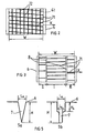
- Figure 1 is shown only a portion of a tire 1 of size 125/80 R 18 seen in a meridian section, that is to say in a cutting plane containing the axis of rotation of said tire.
- the 1 comprises a radial carcass reinforcement 2 surmounted radially on the outside by a crown reinforcement belt 3.
- the reinforcing belt 3 has a surface 4 located radially on the outside and on which is fixed permanently a strip of bearing 5 having a rolling surface 6 located radially outwardly and intended to come into contact with the ground.
- the tread 5 is composed in the axial direction of a single circumferential band 61 of the same width W as the tread 5, corresponding to the effective width of said strip coming into contact with the road under the effect of crushing the tire and rolling it.
- the thickness E is measured, for example, in the middle of the width of the tread 5, between the running surface 6 of said strip and the radially outer surface 4 of the crown reinforcing belt 3.
- the running surface 6 is convex, that is to say that all the points of a segment connecting any two points of the running surface 6 are located radially inside said surface 6.
- the tread 5 is provided with a plurality of substantially transverse orientation incisions 71 and a plurality of circumferentially oriented incisions 72; the incisions 71 make a small angle with respect to the axial direction X, in this case 5 °.
- the transverse and circumferential incisions all have the same width equal to 0.5 mm, said width remaining constant over almost the entire depth of said incisions.
- the transverse and circumferential incisions are evenly distributed with the same pitch equal to 10 mm, which corresponds to a transverse notching rate of about 5% and a circumferential notching rate of about 5%.
- Table I presented below, the values, measured at 90 km / h, of the rolling resistance of several 125/80 R 18 tires inflated to a pressure of 3.5 bar and bearing a load of 400 daN are given. each tire being distinguished from others only by the sculpture of its tread.
- the value of the rolling resistance of the smooth tread tire is taken as a base 100 reference, and a value below 100 must be understood as a lower value of the rolling resistance.
- the rolling surface 6 of width W is divided axially into three circumferential bands of indices (I), (II), (III) of unequal widths.
- the circumferential band of index (I) is in the intermediate position and separated from the other two circumferential bands of indices (II) and (III) by a circumferential cut 8 of width 5 mm.
- Each circumferential band is provided with transverse incisions 71 of width 0.5 mm arranged regularly in the circumferential direction but with a pitch that is two times smaller for the circumferential band (I) than for the other two bands (II) and (III) .
- FIG. 4 shows the impression on a plane floor of another tread sculpture of a radial tire of dimension 175/70 R 13, said tread pattern being defined according to the invention.
- This footprint corresponds to the areas of the tread that come into contact with the ground.
- the sculpture is composed of three circumferential grooves of width 5 mm delimiting, on the rolling surface and in the transverse direction, four circumferential bands; the two circumferential bands on the outer edges of the tread are of smaller width than the two intermediate circumferential bands located in the central region.
- On each band circumferential is formed a network of incisions of width 0.5 mm in transverse and circumferential direction, said incisions being evenly spaced in both directions of the same pitch equal to 7 mm.
- FIG. 5a shows an incision 7 of which a cut is in the form of a V, the maximum width L 0 of said incision corresponding to the width of the incision measured on the running surface of the new tire in the inflated state. and the depth H being greater than the maximum allowable height, so that it closes almost completely regardless of the state of wear of the tread 5.
- FIG. 5b shows an equivalent embodiment obtained by making an incision 7 having, starting from the running surface 6 and at a depth H 0, a constant width L 0 and then, to the depth H, a second constant width L 1 and such that L 1 ⁇ L 0 .
- the sculpture according to the invention can of course be combined with the use of a tread made of a material of low hysteretic loss so as to amplify the beneficial effect on the rolling resistance of the tire.
- this invention is applied to the case of a passenger car tire, said tire comprising at least one radial carcass reinforcement, that is to say composed of reinforcing elements arranged in the meridional direction of the tire, surmounted a reinforcement belt itself surmounted by a tread.
Landscapes
- Engineering & Computer Science (AREA)
- Mechanical Engineering (AREA)
- Tires In General (AREA)
Applications Claiming Priority (2)
| Application Number | Priority Date | Filing Date | Title |
|---|---|---|---|
| FR9601254 | 1996-01-30 | ||
| FR9601254A FR2744067A1 (fr) | 1996-01-30 | 1996-01-30 | Bande de roulement pour pneumatique |
Publications (2)
| Publication Number | Publication Date |
|---|---|
| EP0787601A1 EP0787601A1 (fr) | 1997-08-06 |
| EP0787601B1 true EP0787601B1 (fr) | 2007-01-03 |
Family
ID=9488755
Family Applications (1)
| Application Number | Title | Priority Date | Filing Date |
|---|---|---|---|
| EP97100844A Expired - Lifetime EP0787601B1 (fr) | 1996-01-30 | 1997-01-21 | Bande de roulement pour pneumatique |
Country Status (6)
| Country | Link |
|---|---|
| US (1) | US5918654A (enExample) |
| EP (1) | EP0787601B1 (enExample) |
| JP (1) | JP4271266B2 (enExample) |
| CA (1) | CA2196095A1 (enExample) |
| DE (1) | DE69737167T2 (enExample) |
| FR (1) | FR2744067A1 (enExample) |
Cited By (1)
| Publication number | Priority date | Publication date | Assignee | Title |
|---|---|---|---|---|
| WO2011073313A1 (fr) | 2009-12-17 | 2011-06-23 | Societe De Technologie Michelin | Pneu a faible resistance au roulement |
Families Citing this family (18)
| Publication number | Priority date | Publication date | Assignee | Title |
|---|---|---|---|---|
| IT1289182B1 (it) * | 1997-01-20 | 1998-09-29 | Pirelli | Pneumatico a bassa resistenza di rotolamento in particolare per ruote motrici di veicoli pesanti |
| US6412531B1 (en) * | 1999-07-15 | 2002-07-02 | Michelin Recherche Et Technique S.A. | Tire tread having groove walls with compound contours |
| USD458584S1 (en) | 2001-08-09 | 2002-06-11 | The Goodyear Tire & Rubber Company | Tire tread |
| FR2890600B1 (fr) * | 2005-09-15 | 2010-02-26 | Michelin Soc Tech | Dispositif anti-usure irreguliere pour bande de roulement de pneumatique |
| FR2898298B1 (fr) * | 2006-03-08 | 2010-08-20 | Michelin Soc Tech | Incision de bande de roulement comprenant des parties de blocage. |
| JP4964560B2 (ja) * | 2006-10-23 | 2012-07-04 | 東洋ゴム工業株式会社 | 空気入りタイヤ |
| FR2964600B1 (fr) * | 2010-09-09 | 2014-08-22 | Michelin Soc Tech | Bande de roulement pour pneumatique |
| FR2999473B1 (fr) * | 2012-12-14 | 2015-03-20 | Michelin & Cie | Pneumatique ayant une basse resistance au roulement |
| JP6076818B2 (ja) | 2013-04-23 | 2017-02-08 | 株式会社ブリヂストン | 航空機用タイヤ |
| FR3013261A1 (fr) | 2013-11-20 | 2015-05-22 | Michelin & Cie | Bande de roulement et pneumatique |
| CN106457921B (zh) * | 2014-06-30 | 2019-04-02 | 米其林集团总公司 | 轮胎胎面和轮胎的可变宽度胎纹沟槽 |
| CN107278184B (zh) * | 2014-12-31 | 2019-09-13 | 米其林集团总公司 | 具有改进干式/雪地牵引的轮胎胎面 |
| JP6527758B2 (ja) * | 2015-06-13 | 2019-06-05 | 株式会社ブリヂストン | 空気入りタイヤ |
| JP6769729B2 (ja) * | 2016-04-18 | 2020-10-14 | 株式会社ブリヂストン | タイヤ |
| US10065457B2 (en) * | 2016-07-05 | 2018-09-04 | Shinji Marui | Tire with offset beveled knobs |
| WO2018044305A1 (en) | 2016-08-31 | 2018-03-08 | Compagnie Generale Des Etablissements Michelin | Tire tread |
| KR101901064B1 (ko) * | 2017-06-08 | 2018-09-20 | 한국타이어 주식회사 | 윈터 타이어의 커프 |
| JP2024086466A (ja) * | 2022-12-16 | 2024-06-27 | 株式会社ブリヂストン | タイヤ |
Citations (1)
| Publication number | Priority date | Publication date | Assignee | Title |
|---|---|---|---|---|
| US4298046A (en) * | 1979-07-24 | 1981-11-03 | Compagnie Generale Des Etablissements Michelin | Winter tire |
Family Cites Families (10)
| Publication number | Priority date | Publication date | Assignee | Title |
|---|---|---|---|---|
| US2109691A (en) * | 1932-03-12 | 1938-03-01 | D Ayguesvives Serge | Pneumatic tire |
| NL66975C (enExample) * | 1932-11-04 | |||
| GB518601A (en) * | 1938-10-15 | 1940-03-01 | Bull John Rubber Company Ltd | Improvements in pneumatic tyres |
| GB727207A (en) * | 1952-06-24 | 1955-03-30 | Goodrich Co B F | Improvements in or relating to a high speed tire |
| US2926715A (en) * | 1956-11-23 | 1960-03-01 | Us Rubber Co | Tire tread |
| JPS58194605A (ja) * | 1982-05-07 | 1983-11-12 | Sumitomo Rubber Ind Ltd | レ−ス用タイヤ |
| JPH0253611A (ja) * | 1988-08-19 | 1990-02-22 | Yokohama Rubber Co Ltd:The | 重荷重用空気入りラジアルタイヤ |
| AT394002B (de) * | 1989-01-27 | 1992-01-27 | Semperit Ag | Radialreifen fuer raeder von lkw-antriebsachsen |
| FR2669273A1 (fr) * | 1990-11-15 | 1992-05-22 | Michelin & Cie | Bande de roulement d'enveloppe de pneumatique pour vehicules poids-lourds. |
| JPH07228106A (ja) * | 1994-02-17 | 1995-08-29 | Bridgestone Corp | 空気入りタイヤ |
-
1996
- 1996-01-30 FR FR9601254A patent/FR2744067A1/fr active Pending
-
1997
- 1997-01-21 EP EP97100844A patent/EP0787601B1/fr not_active Expired - Lifetime
- 1997-01-21 DE DE69737167T patent/DE69737167T2/de not_active Expired - Lifetime
- 1997-01-27 CA CA002196095A patent/CA2196095A1/fr not_active Abandoned
- 1997-01-27 US US08/789,656 patent/US5918654A/en not_active Expired - Lifetime
- 1997-01-30 JP JP01694697A patent/JP4271266B2/ja not_active Expired - Lifetime
Patent Citations (1)
| Publication number | Priority date | Publication date | Assignee | Title |
|---|---|---|---|---|
| US4298046A (en) * | 1979-07-24 | 1981-11-03 | Compagnie Generale Des Etablissements Michelin | Winter tire |
Cited By (1)
| Publication number | Priority date | Publication date | Assignee | Title |
|---|---|---|---|---|
| WO2011073313A1 (fr) | 2009-12-17 | 2011-06-23 | Societe De Technologie Michelin | Pneu a faible resistance au roulement |
Also Published As
| Publication number | Publication date |
|---|---|
| CA2196095A1 (fr) | 1997-07-31 |
| US5918654A (en) | 1999-07-06 |
| EP0787601A1 (fr) | 1997-08-06 |
| JP4271266B2 (ja) | 2009-06-03 |
| DE69737167D1 (de) | 2007-02-15 |
| FR2744067A1 (fr) | 1997-08-01 |
| JPH09207523A (ja) | 1997-08-12 |
| DE69737167T2 (de) | 2007-10-04 |
Similar Documents
| Publication | Publication Date | Title |
|---|---|---|
| EP0787601B1 (fr) | Bande de roulement pour pneumatique | |
| EP1035978B1 (fr) | Armature de sommet de pneumatique | |
| EP2694302B1 (fr) | Bande de roulement comprenant au moins une rainure ondulante et procédé d'obtention | |
| EP3160773B1 (fr) | Bande de roulement incisée pour pneu génie civil | |
| EP2788204B1 (fr) | Combinaison d'une structure de pneu poids lourd avec une sculpture de bande de roulement | |
| EP3648991B1 (fr) | Pneu dont la bande de roulement comprend des rainures ondulantes | |
| EP3439897B1 (fr) | Bande de roulement pour pneu | |
| FR2967940A1 (fr) | Pneu poids lourd pour vehicule remorque | |
| FR3014747A1 (fr) | Bande de roulement evolutive pour pneu | |
| EP1638785B1 (fr) | Element protecteur d'une bande de roulement | |
| EP3433111B1 (fr) | Bande de roulement pour un pneu | |
| EP3687837B1 (fr) | Pneu pour véhicule hors-la-route ayant une endurance ameliorée | |
| EP1638786B1 (fr) | Bande de roulement comportant une nervure sacrifiee ventilee | |
| EP3703958A1 (fr) | Bande de roulement pour pneu de véhicule poids lourd | |
| EP3523141A1 (fr) | Pneu pour véhicule destiné à porter de lourdes charges | |
| EP3681737B1 (fr) | Moule de bande de roulement de pneu comprenant des canaux cachés | |
| EP3390105B1 (fr) | Pneumatique présentant des propriétés d'usure améliorées | |
| EP3898279B1 (fr) | Bande de roulement comportant des cavites cachees et des rainures | |
| WO2017174927A1 (fr) | Bande de roulement améliorée pour pneu | |
| WO2020128235A1 (fr) | Bande de roulement comportant des cavites cachees et des rainures | |
| EP3390078B1 (fr) | Pneumatique presentant des proprietes d'usure ameliorees | |
| WO2023194096A1 (fr) | Pneumatique comportant une bande de roulement recreusable |
Legal Events
| Date | Code | Title | Description |
|---|---|---|---|
| PUAI | Public reference made under article 153(3) epc to a published international application that has entered the european phase |
Free format text: ORIGINAL CODE: 0009012 |
|
| AK | Designated contracting states |
Kind code of ref document: A1 Designated state(s): DE FR GB IT |
|
| 17P | Request for examination filed |
Effective date: 19980206 |
|
| GRAP | Despatch of communication of intention to grant a patent |
Free format text: ORIGINAL CODE: EPIDOSNIGR1 |
|
| GRAS | Grant fee paid |
Free format text: ORIGINAL CODE: EPIDOSNIGR3 |
|
| GRAA | (expected) grant |
Free format text: ORIGINAL CODE: 0009210 |
|
| AK | Designated contracting states |
Kind code of ref document: B1 Designated state(s): DE FR GB IT |
|
| REG | Reference to a national code |
Ref country code: GB Ref legal event code: FG4D Free format text: NOT ENGLISH |
|
| REF | Corresponds to: |
Ref document number: 69737167 Country of ref document: DE Date of ref document: 20070215 Kind code of ref document: P |
|
| PGFP | Annual fee paid to national office [announced via postgrant information from national office to epo] |
Ref country code: GB Payment date: 20070220 Year of fee payment: 11 |
|
| PLBE | No opposition filed within time limit |
Free format text: ORIGINAL CODE: 0009261 |
|
| STAA | Information on the status of an ep patent application or granted ep patent |
Free format text: STATUS: NO OPPOSITION FILED WITHIN TIME LIMIT |
|
| 26N | No opposition filed |
Effective date: 20071005 |
|
| GBPC | Gb: european patent ceased through non-payment of renewal fee |
Effective date: 20080121 |
|
| PG25 | Lapsed in a contracting state [announced via postgrant information from national office to epo] |
Ref country code: GB Free format text: LAPSE BECAUSE OF NON-PAYMENT OF DUE FEES Effective date: 20080121 |
|
| REG | Reference to a national code |
Ref country code: FR Ref legal event code: PLFP Year of fee payment: 20 |
|
| PGFP | Annual fee paid to national office [announced via postgrant information from national office to epo] |
Ref country code: IT Payment date: 20160127 Year of fee payment: 20 Ref country code: DE Payment date: 20160120 Year of fee payment: 20 |
|
| PGFP | Annual fee paid to national office [announced via postgrant information from national office to epo] |
Ref country code: FR Payment date: 20160121 Year of fee payment: 20 |
|
| REG | Reference to a national code |
Ref country code: DE Ref legal event code: R071 Ref document number: 69737167 Country of ref document: DE |