EP0787560B2 - Vorrichtung zum Bearbeiten von Stangenmaterial, Profilen und dergleichen - Google Patents
Vorrichtung zum Bearbeiten von Stangenmaterial, Profilen und dergleichen Download PDFInfo
- Publication number
- EP0787560B2 EP0787560B2 EP97100989A EP97100989A EP0787560B2 EP 0787560 B2 EP0787560 B2 EP 0787560B2 EP 97100989 A EP97100989 A EP 97100989A EP 97100989 A EP97100989 A EP 97100989A EP 0787560 B2 EP0787560 B2 EP 0787560B2
- Authority
- EP
- European Patent Office
- Prior art keywords
- profile
- clamping
- shaft
- machining
- processing unit
- Prior art date
- Legal status (The legal status is an assumption and is not a legal conclusion. Google has not performed a legal analysis and makes no representation as to the accuracy of the status listed.)
- Expired - Lifetime
Links
Images

Classifications
-
- B—PERFORMING OPERATIONS; TRANSPORTING
- B27—WORKING OR PRESERVING WOOD OR SIMILAR MATERIAL; NAILING OR STAPLING MACHINES IN GENERAL
- B27F—DOVETAILED WORK; TENONS; SLOTTING MACHINES FOR WOOD OR SIMILAR MATERIAL; NAILING OR STAPLING MACHINES
- B27F5/00—Slotted or mortised work
- B27F5/02—Slotting or mortising machines tools therefor
- B27F5/12—Slotting or mortising machines tools therefor for making holes designed for taking up fittings, e.g. in frames of doors, windows, furniture
-
- B—PERFORMING OPERATIONS; TRANSPORTING
- B23—MACHINE TOOLS; METAL-WORKING NOT OTHERWISE PROVIDED FOR
- B23Q—DETAILS, COMPONENTS, OR ACCESSORIES FOR MACHINE TOOLS, e.g. ARRANGEMENTS FOR COPYING OR CONTROLLING; MACHINE TOOLS IN GENERAL CHARACTERISED BY THE CONSTRUCTION OF PARTICULAR DETAILS OR COMPONENTS; COMBINATIONS OR ASSOCIATIONS OF METAL-WORKING MACHINES, NOT DIRECTED TO A PARTICULAR RESULT
- B23Q1/00—Members which are comprised in the general build-up of a form of machine, particularly relatively large fixed members
- B23Q1/25—Movable or adjustable work or tool supports
- B23Q1/44—Movable or adjustable work or tool supports using particular mechanisms
- B23Q1/50—Movable or adjustable work or tool supports using particular mechanisms with rotating pairs only, the rotating pairs being the first two elements of the mechanism
- B23Q1/52—Movable or adjustable work or tool supports using particular mechanisms with rotating pairs only, the rotating pairs being the first two elements of the mechanism a single rotating pair
- B23Q1/527—Movable or adjustable work or tool supports using particular mechanisms with rotating pairs only, the rotating pairs being the first two elements of the mechanism a single rotating pair with a ring or tube in which a workpiece is fixed coaxially to the degree of freedom
-
- Y—GENERAL TAGGING OF NEW TECHNOLOGICAL DEVELOPMENTS; GENERAL TAGGING OF CROSS-SECTIONAL TECHNOLOGIES SPANNING OVER SEVERAL SECTIONS OF THE IPC; TECHNICAL SUBJECTS COVERED BY FORMER USPC CROSS-REFERENCE ART COLLECTIONS [XRACs] AND DIGESTS
- Y10—TECHNICAL SUBJECTS COVERED BY FORMER USPC
- Y10T—TECHNICAL SUBJECTS COVERED BY FORMER US CLASSIFICATION
- Y10T408/00—Cutting by use of rotating axially moving tool
- Y10T408/55—Cutting by use of rotating axially moving tool with work-engaging structure other than Tool or tool-support
- Y10T408/561—Having tool-opposing, work-engaging surface
- Y10T408/5614—Angularly adjustable surface
-
- Y—GENERAL TAGGING OF NEW TECHNOLOGICAL DEVELOPMENTS; GENERAL TAGGING OF CROSS-SECTIONAL TECHNOLOGIES SPANNING OVER SEVERAL SECTIONS OF THE IPC; TECHNICAL SUBJECTS COVERED BY FORMER USPC CROSS-REFERENCE ART COLLECTIONS [XRACs] AND DIGESTS
- Y10—TECHNICAL SUBJECTS COVERED BY FORMER USPC
- Y10T—TECHNICAL SUBJECTS COVERED BY FORMER US CLASSIFICATION
- Y10T408/00—Cutting by use of rotating axially moving tool
- Y10T408/55—Cutting by use of rotating axially moving tool with work-engaging structure other than Tool or tool-support
- Y10T408/563—Work-gripping clamp
- Y10T408/5635—Oppositely moving lateral clamps
-
- Y—GENERAL TAGGING OF NEW TECHNOLOGICAL DEVELOPMENTS; GENERAL TAGGING OF CROSS-SECTIONAL TECHNOLOGIES SPANNING OVER SEVERAL SECTIONS OF THE IPC; TECHNICAL SUBJECTS COVERED BY FORMER USPC CROSS-REFERENCE ART COLLECTIONS [XRACs] AND DIGESTS
- Y10—TECHNICAL SUBJECTS COVERED BY FORMER USPC
- Y10T—TECHNICAL SUBJECTS COVERED BY FORMER US CLASSIFICATION
- Y10T409/00—Gear cutting, milling, or planing
- Y10T409/30—Milling
- Y10T409/306664—Milling including means to infeed rotary cutter toward work
- Y10T409/307448—Milling including means to infeed rotary cutter toward work with work holder
- Y10T409/307504—Indexable
-
- Y—GENERAL TAGGING OF NEW TECHNOLOGICAL DEVELOPMENTS; GENERAL TAGGING OF CROSS-SECTIONAL TECHNOLOGIES SPANNING OVER SEVERAL SECTIONS OF THE IPC; TECHNICAL SUBJECTS COVERED BY FORMER USPC CROSS-REFERENCE ART COLLECTIONS [XRACs] AND DIGESTS
- Y10—TECHNICAL SUBJECTS COVERED BY FORMER USPC
- Y10T—TECHNICAL SUBJECTS COVERED BY FORMER US CLASSIFICATION
- Y10T409/00—Gear cutting, milling, or planing
- Y10T409/30—Milling
- Y10T409/30868—Work support
- Y10T409/308792—Indexable
Definitions
- the invention relates to a device according to the preamble of claim 1.
- a device is known from US-3,918,145-A.
- the clamping device is mounted pivotably about a horizontal pivot axis, wherein the clamping device is mounted in the machine frame about a parallel to the longitudinal axis of the hollow profile pivot axis by at least 180 ° ,
- the holder of the hollow profile is carried out by compressed air actuated clamping cylinder, which clamp the hollow profile with respect to a contact surface.
- a circular arc guide By means of a circular arc guide the hollow profile is pivoted about a pivot axis parallel to the longitudinal axis of the hollow profile.
- the drive of the hollow profile via arranged on the machine frame bearing rollers.
- the rotary actuator is actuated by two pressure medium swivel cylinder, the drive for pivoting the hollow profile is designed very expensive and the storage of the jig.
- Machines of the type mentioned are known. On a machine table, the profile to be machined is clamped. In the profiles, for example, plastic, wood or metal profiles can be used. On the profiles, which are processed or processed, for example, as Stangenpreßprofile or extruded profiles, preparatory work is to be carried out. For example, windows are produced from the profiles, wherein recesses for the fitting of valves, drives or the like are to be provided in the profiles.
- the tool carrier In the processing of this bar material, it is disadvantageous that they are to be processed on a plurality of sides.
- the tool carrier is designed to be pivotable and thereby a multi-side machining of the profile is possible.
- Such a configuration is correspondingly expensive, since the tool carrier, in particular the tool spindles, must have a high precision and the corresponding Verschwenkmechaniscmus must also have a high quality.
- the invention proceeds from the device, as described above, and proposes a device according to claim 1.
- Such an embodiment of the invention ensures that the profile can be processed in a simple manner on several sides. If, for example, a side is used as the visible side in the case of a four-sided profile, pivotability of the device through 180 °, for example, is sufficient. Of course it's possible; to edit any other profile shape by then the corresponding pivoting range of the device is selected.
- the two shafts are connected by a worktable.
- the production of long waves is difficult in high quality.
- a plurality of bearings are provided in order to derive the weight of the shaft and also the forces occurring during the machining of the profile holder on the machine frame. These bearings also support the worktable provided between the shafts. It is also envisaged that both a rigid connection between the two shaft parts is realized, as well as a respective independent drive for the two shafts.
- the device has a lock which locks the profile holder.
- a lock which locks the profile holder.
- a locking pin is inserted in the device.
- the Arritieremia has, for example, in its periphery openings into which a locking pin can be inserted by a pneumatically actuated piston.
- the Arritierstatt is provided here, for example, on the machining table.
- the locking is provided at the end of the shaft.
- a lock can be provided in the central portion of the shaft.
- the change of the lock, in particular the locking disc is favorable if it is provided at the end of the shaft.
- the locking disc may, for example, have different angular divisions.
- the openings are arranged at a distance of 90 ° to each other.
- the openings may in this case be arranged, for example, radially or parallel to the shaft.
- a servomotor is provided as the pivoting drive.
- a servo motor stepless angle adjustment of the pivoting device is possible. It is provided, for example, that the pivoting drive attacks both ends of the shaft and has a corresponding synchronization control.
- a servomotor two different, complementary effects can be achieved. On the one hand, it is possible to realize a uniform movement by the servo motor, in which case a corresponding machining of the workpiece is possible.
- any adjustment of the profile with respect to the processing machines can be achieved by the servo motor.
- the servo motor has a corresponding brake or lock, so that the selected setting is fixed and processing is done easily.
- the servomotor can, for example, directly attack the shaft or act on the shaft via a toothed belt.
- pivoting drives and geared motors or the like can be provided.
- a processing unit is provided on the device, which processes the sides and / or the end face of the profile.
- the processing unit for example a tool spindle with devices for drilling, milling or a processing machine or the like, is for example longitudinally displaceable, parallel to the longitudinal axis of the profile (X-axis), provided on the device.
- the processing unit also has a mobility in the direction of the Y-axis, ie in the horizontal plane.
- the processing unit processes the profile during the pivoting movement of the pivoting drive. This makes it possible to bring elaborate milling work, etc. in the profile, without providing another processing machine for this purpose. In particular, thus milling on the circumference of the profile or the like are easily possible.
- the profile clamping device comprises a clamping slide, which is movable along the shaft. This ensures that machining is possible even with clamped profiles in which actually the profile clamping device would interfere, for example, because the profile is held in a position to be processed. For this purpose, not the entire profile must be removed and moved, but only the disturbing profile clamping device can be solved and offset. The profile is released and the clamping device is released on the profile clamping device to then move it to the shaft.
- the profile clamping device has clamping jaws which hold the profile like a pincers on the side.
- Such an embodiment is realized by a simple and effective profile clamping device. It is provided that for the clamping jaws, for example, a pneumatic or hydraulic actuation is provided. Depending on the application, thus different pressures can be given to the jaws and according to the holding forces can be varied. This is particularly advantageous when machining different profile materials (metal or plastic).
- both jaws perform a same clamping movement for the centric clamping of the profile.
- the axes of the profile are still defined.
- the apparatus for processing bar material 10, profiles or the like is shown.
- the device 1 has a machine table 12 on which the profiles 10 are mounted with the aid of the profile holder 3.
- the processing unit 6 is, for example, a high-speed tool spindle, a milling cutter, a drill, a planer or the like.
- the processing unit 6 is displaceable parallel to the longitudinal axis 11 of the profile 10, arranged in the direction of the X-axis.
- the processing unit is also movable in the other two spatial axes, ie the Y and Z axes. As a result, a positioning of the processing unit 6 in height or in depth is achieved.
- the processing unit 6 is designed, for example, also pivotable or has an angle drive to edit, for example, the end face 13 of the profile 10.
- a two-part shaft 31,32 is provided as a profile holder 3.
- This division of the shaft has the advantage that relatively short shafts are easy to produce and a majority of these waves form a long profile holder. As a result, a great flexibility of the device is achieved. Also, the production of short waves is easier and less expensive. A majority of the waves is in this case arranged so that they are ever in alignment.
- the two shafts 31, 32 are rigidly connected to one another via the clamping table 36.
- a plurality of supports 15 are provided which bear bearings 14 in which the shaft 30 is mounted.
- the clamping table 36 is connected by support bearings 37 with the shaft.
- the profile holder at each of its ends on a lock 5. This ensures that the profile holder 3, for example, the shaft 30, is optimally maintained in the pivoted position.
- the possible use of the device is further increased if, for example, provided that on a machine table 12 not only a profile holder 3 is provided, but a plurality of profile mounts.
- the advantage is achieved that a processing unit 6 is provided which cooperates, for example, with two profile mounts 3. It is now, for example, a processing possible so that the first profile holder on the profile is changed, while the processing unit 6 to the profile, which is provided on the left profile holder, making operations.
- the high cost of a tool spindle, in particular a high-speed spindle, are thus optimally utilized with the device according to the invention.
- the lock 5 consists of a locking disc 50 which is attached to the end of the shaft 30.
- the locking disc 50 is formed, for example, circular. But it is also possible that the locking disc 50 consists of a half-disc, in the upper portion 10 at right angles to the disc, a strut 58 or a support is formed, as is indicated for example in Fig. 3. In such a configuration then, for example, the locking disk 50 still acts as a stop 57 for the profile 10 held on the mounting slide 38, wherein the strut 58 carries the stop 57.
- the support plane of the profile is arranged on the clamping device on the device for locking, in particular the locking disc.
- the stop 57 is connected by a strut 58 with the disc 50. With the strut 58, the stop 57 engages over the end bearing 16 and the support 15 in which the shaft 30 is mounted. As indicated in Fig. 4, the stopper 57 is formed almost resting on the shaft 30.
- a lock is provided by an insertable into the disc locking pin 54. Furthermore, it is provided that a servo motor 22 is provided as a pivot drive 20 for stepless adjustment, the has a corresponding brake or clutch to hold the pivoted profile holder in the desired position. Furthermore, it can be provided that the shaft 30 and the profile holder 3 is formed in its end region as a splined shaft, and this spline is determined by corresponding locking positions.
- a locking disc 50 In the formation of the lock 5 by a locking disc 50 is provided that the disc 50 has radial openings 51,52, 53, in which a locking pin 54 is inserted.
- the locking pin 54 is actuated by a working cylinder 55. This can be for example a pneumatic cylinder or an electric drive.
- the pin 54 or the working cylinder 55 is provided here, for example, on the machine table.
- the pin 54 has a conical tip 56. As a result, the retraction of the pin 54 is achieved in the openings 51,52,53 and causes a stable, mechanical connection between the disc and the machine table 12.
- the distance between the openings 51,52 53 at the periphery of the disc 50 is 90 °.
- a 3-sided machining of the clamped profile or bar material is easily possible.
- the openings 51,52,53 with respect to additional openings it is easily possible to realize any other angular adjustment.
- an axial lock is conceivable in which the arrangement of the pin 54 in the axial direction, for example, the shaft 30, takes place.
- a servomotor 22 forms the catch 5. Such a configuration is particularly advantageous when various angle settings are desired.
- the servo motor 22 is then provided, for example, at both ends of the profile holder 3 in order to optimally hold it.
- the servomotor 22 has a clutch or brake to securely lock the position.
- the control acts in common on the servomotor acting on the profile holder, so that a uniform movement and locking of these servomotors is ensured.
- the clamping carriage 38 is shown, which is arranged on the shaft 30.
- the clamping slide 38 is clamped on the shaft 30, so that a pivoting of the shaft 30 also leads to a pivoting of the clamping slide 38.
- the clamping slide 38 is supported on the shaft 30 via the linear bearing 39.
- the clamping slide 38 can be moved manually or pneumatically on the guide shaft 30 and fixed on the shaft 30 in any position. This is particularly advantageous when a profile machining is to be made at locations that are hidden by the clamping jaws 40.
- FIGS. 5a, 5b and 5c the device according to the invention is shown in three different pivoted positions.
- the pivoting device 2 causes a pivoting of the profile holder 3 about an axis which is parallel to the longitudinal axis of the rod material 10.
- the profile holder 3 is pivoted about the axis 34 of the shaft 30.
- the pivoting movement is indicated by the arrow 25.
- operations are performed with the processing unit.
- the processing unit 6 has a mobility at least in the three spatial axes X, Y and Z.
- the X-axis (double arrow 62) is described here by the orientation of the axis 34 and the longitudinal axis 11 of the rod material 10.
- the Y-axis is the horizontal perpendicular to the X-axis.
- the Y-axis is indicated by the double arrow 60. Due to the mobility in the Z direction (arrow 61) a height adjustment is easily possible.
- Fig. 5c is shown that with respect to the position in Fig. 5a, the processing unit 6 is shifted relative to the axis 34 to the right.
- a positioning unit 7 For a movement of the processing unit 6 in the three spatial axes X (62), Y (60) and Z (61), a positioning unit 7 is provided.
- This positioning unit 7 consists of a rail track 70, which is arranged substantially parallel to the longitudinal axis 34 of the shaft 30 of the profile holder 3.
- a carriage 71 On this rail track 70, a carriage 71 is provided, which carries the processing unit 6.
- the drive for the processing unit 6 is provided and a height adjustment (Z-axis) for the processing unit or an adjustability (Y-axis) transverse to the longitudinal axis 34 of the shaft 30.
- the positioning unit 7, which is arranged above the processing table 12 is, but can also be arranged transversely to the longitudinal extension of the profile displaceable or movable.
- the rail track 70 is held on a strut 72, wherein the processing unit 6, for example, edited from above the profile.
- the processing unit 6 for example, edited from above the profile.
- another processing unit 65 is selectively used to edit, for example, the end face of the profile.
- the processing unit 65 optionally has a propulsion in the X direction (62).
- processing unit 6 is typically at least a 3-axis tool spindle. Due to the embodiment of the invention, however, it is achieved that can be dispensed with a more complex mobility of the tool spindle with respect to as versatile as possible processing of the rod material.
- the profile clamping device 35 is shown in partial section.
- the profile clamping device 35 is arranged on the shaft 30.
- clamping jaws 40,45 are provided, which take the profile on the side of pincers.
- the jaws 40,45 perform a uniform movement.
- a common drive is provided for the drive the two clamping jaws 40, whose movement is indicated by the double arrow 41.
- a pneumatically or hydraulically actuated cylinder acts on a pull plate.
- This tension plate has a slotted guide for the two jaws 40,45.
- a sliding block which is connected to the jaw, engages in the respective slotted guide.
- a movement of the tension plate takes place, and the movements result according to the arrow 41 of the clamping jaws 40, 45.
- a bearing of the clamping jaws 40,45 is provided on the clamping saddle 42. The bearing for this purpose is marked 43.
- the jaws 40 can be used in different basic positions.
- the clamping jaws 40 sit on a Einstellschlitten, and the Einstellschlitten has the backdrop for the slotted guide.
- the clamping jaws are secured with screws on the adjusting slide, for example.
- the Einstellschlitten has notches, which are provided at a shorter distance than the maximum clamping range of the clamping jaws.
- any profile thickness can be kept between a minimum and maximum dimensions.
- the jaws are applied for example pneumatically or hydraulically.
- the application takes place, for example, on said working cylinder.
- a pneumatic impingement may be sufficient, for example, when holding plastic profiles, since in this machining the forces occurring are lower than in a metalworking.
- At high loads for example, provided that a hydraulic admission takes place.
- the working cylinder is in this case acted upon on both sides, a movement of the clamping jaws in the locking or release direction is actuated in each case by the working cylinder.
- a geared motor 23 is provided which acts on the shaft 30 via a toothed belt or V-belt 24.
- a controller 8 For monitoring the movement of the processing unit 6, a controller 8 is provided.
- the processing unit 6 is in this case connected via the data line 81 to the controller 8.
- the controller 8 determines the processing position, that is to say the coordinates along the axes of motion, in this case the three spatial axes.
- the controller 8 with the pivoting drive 20, so the servo motor 22 or the geared motor 23, connected and controls the rotation of the profile.
- the lock 5 is connected to the controller 8. Before rotating the profile for a new machining, the locking is released via this data line so that the pivoting device 2 can pivot the profile 10.
- the lock can be closed again or when using a servomotor 22, a corresponding brake or clutch can be actuated.
- the controller 8 takes into account the new working coordinates for a pivoted profile, since, for example, the controller knows the dimension of the profile, as well as the angle of rotation and adds this information to the machining coordinates on the profile mutatis mutandis and thus determines the new machining position of the tool spindle or the like.
- the device has a machining table and the pivoting device can be mounted on the machining table.
- the pivoting device is mounted, for example, on the base plate of the machining table.
- the pivoting device for example, connections for power and control lines, whereby a smooth integration into the device is possible.
- the signals for the rotation of the profile are transmitted via the control line.
Landscapes
- Engineering & Computer Science (AREA)
- Life Sciences & Earth Sciences (AREA)
- Mechanical Engineering (AREA)
- Wood Science & Technology (AREA)
- Forests & Forestry (AREA)
- Jigs For Machine Tools (AREA)
- Machine Tool Units (AREA)
- Electrical Discharge Machining, Electrochemical Machining, And Combined Machining (AREA)
- Forging (AREA)
- Turning (AREA)
- Metal Extraction Processes (AREA)
- Load-Engaging Elements For Cranes (AREA)
Description
- Die Erfindung betrifft eine Vorrichtung nach dem Oberbegriff des Anspruchs 1. Eine derartige Vorrichtung ist aus der US-3 918 145-A bekannt.
- Aus der EP-A-0 558 982 geht eine Vorrichtung zur mehrseitigen Bearbeitung von Hohlprofilen hervor, deren Aufspanneinrichtung um eine horizontale Schwenkachse schwenkbar gelagert ist, wobei die Aufspanneinrichtung im Maschinengestell um eine parallel zur Längsachse des Hohlprofiles verlaufende Schwenkachse um mindestens 180° schwenkbar gelagert ist. Die Halterung des Hohlprofiles erfolgt durch druckluftbetätigte Spannzylinder, die das Hohlprofil gegenüber einer Anlagefläche spannen. Mittels einer Kreisbogenführung wird das Hohlprofil um eine Schwenkachse parallel zur Längsachse des Hohlprofils verschwenkt. Der Antrieb des Hohlprofils erfolgt über am Maschinengestell angeordneten Lagerrollen. Der Schwenkantrieb erfolgt über zwei Druckmittel betätigte Schwenkzylinder, der Antrieb zum Schwenken des Hohlprofils ist sehr aufwendig gestaltet sowie die Lagerung der Aufspanneinrichtung.
- Maschinen der eingangs angegebenen Gattung sind bekannt. Auf einem Maschinentisch wird das zu bearbeitende Profil aufgespannt. Bei den Profilen können zum Beispiel Kunststoff-, Holz oder Metallprofile Verwendung finden. An den Profilen, die beispielsweise als Stangenpreßprofile oder extrudierte Profile ver- bzw. bearbeitet werden, sind vorbereitende Arbeiten auszuführen. Zum Beispiel werden aus den Profilen Fenster gefertigt, wobei in den Profilen Ausnehmungen für das Einpassen von Armaturen, Antrieben oder dergleichen vorzusehen sind.
- Des weiteren ist zum Beispiel an einem Metallprofil, das für den Fassadenbau verwendet wird, das Aufbringen von zusätzlichen Leisten notwendig, die beispielsweise mit der vorerwähnten Vorrichtung angeschweißt werden.
- Bei der Bearbeitung dieses Stangenmaterials ist es von Nachteil, daß diese an einer Mehrzahl von Seiten zu bearbeiten sind. Hierzu ist es bekannt, daß der Werkzeugträger schwenkbar ausgeführt ist und dadurch eine Mehrseitenbearbeitung des Profiles möglich ist. Eine solche Ausgestaltung ist entsprechend aufwendig, da die Werkzeugträger, insbesondere die Werkzeugspindeln, eine hohe Präzision aufweisen müssen und der entsprechende Verschwenkmechaniscmus auch eine hohe Qualität besitzen muß.
- Es ist Aufgabe der vorliegenden Erfindung, die Vorrichtung zum Bearbeiten von Stangenmaterial zu schaffen, bei der die Bearbeitung des Materials an mehreren Seiten beliebig erfolgen kann, wobei die Vorrichtung einfach und zuverlässig zu bedienen ist.
- Zur Lösung dieser Aufgabe geht die Erfindung aus von der Vorrichtung, wie eingangs beschrieben, und schlagt eine Vorrichtung nach Anspruch 1 vor.
- Eine solche erfindungsgemäße Ausgestaltung erreicht, daß das Profil auf einfache Weise an mehreren Seiten bearbeitbar ist. Wenn zum Beispiel bei einem Vierseitenprofil eine Seite als Sichtseite Verwendung findet, ist beispielsweise eine Verschwenkbarkeit der Vorrichtung um 180° ausreichend. Natürlich ist es möglich; jede beliebige andere Profilform zu bearbeiten, indem dann der entsprechende Verschwenkbereich der Vorrichtung gewählt wird.
- Die aufwendige Lagerung und Verschwenkung der Werkzeugspindel entfällt somit. Auf eine entsprechend aufwendige Konstruktion der Werkzeugspindel kann verzichtet werden.
- Es ist von Vorteil, daß die beiden Wellen durch einen Aufspanntisch verbunden sind. Bei einer solchen Ausgestaltung ist es möglich, auch kurze Profile zu bearbeiten, ohne daß die Wellen eine entsprechende Länge aufweisen müssen. Denn insbesondere das Herstellen von langen Wellen ist in hoher Güte schwierig. Es wird insbesondere beabsichtigt, Profile von mehr als sechs Meter mit der erfindungsgemäßen Vorrichtung zu bearbeiten. Durch die zweiteilige Welle, wobei hierbei auch ein prinzipieller modularer Aufbau vorgesehen sein kann, wird auf einfache Weise erreicht, daß die Vorrichtung auf die entsprechenden Profillängen leicht angepaßt werden kann. Um das Gewicht der Welle und auch die auftretenden Kräfte bei der Bearbeitung von der Profilhalterung auf das Maschinengestell abzuleiten, sind eine Vielzahl von Lager vorgesehen. Diese Lager unterstützen auch den Aufspanntisch, der zwischen den Wellen vorgesehen ist. Es ist auch vorgesehen, daß sowohl eine starre Verbindung zwischen den beiden Wellenteilen realisiert wird, als auch ein jeweils unabhängiger Antrieb für die beiden Wellen.
- Auch ist es günstig, wenn die Vorrichtung eine Arretierung aufweist, die die Profilhalterung arretiert. Durch die Arretierung wird erreicht, daß die verschwenkte Profilhalterung in der gewünschten Winkelstellung sicher gehalten ist und bei der Bearbeitung sich nicht verstellt. Dementsprechend weist die Arretierung Mittel auf, die eine ausreichende Arretierungskraft bilden, daß auch die auf das Werkstück wirkenden Bearbeitungskräfte nicht zu einer ungewollten Verschwenkung der Profilhalterung führen.
- In einer bevorzugten Ausgestaltung der Erfindung ist vorgesehen, daß in die Vorrichtung ein Arretierstift einführbar ist. Die Arritierscheibe weist zum Beispiel in ihrem Umfang Öffnungen auf, in die ein Arretierstift durch einen pneumatisch betätigbaren Kolben eingeführt werden kann. Der Arritierstift ist hierbei beispielsweise an dem Bearbeitungstisch vorgesehen.
- Insbesondere ist es günstig, wenn die Arretierung am Ende der Welle vorgesehen ist. Es kann natürlich auch eine Arretierung im Mittelabschnitt der Welle vorgesehen werden. Das Wechseln der Arretierung, insbesondere der Arretierscheibe, ist dann günstig, wenn diese am Ende der Welle vorgesehen ist. Die Arretierscheibe kann zum Beispiel verschiedene Winkeleinteilungen aufweisen. Hierbei ist es günstig, daß die Öffnungen in einem Abstand von 90° zueinander angeordnet sind. Die Öffnungen können hierbei beispielsweise radial oder parallel zur Welle angeordnet sein. Durch eine Ausgestaltung im Abstand von 90° wird eine Arretierung entsprechend der zu bearbeitenden Seiten eines Vierseitenprofiles erreicht.
- Es ist von Vorteil, wenn als Verschwenkantrieb ein Servomotor vorgesehen ist. Durch einen Servomotor ist eine stufenlose Winkeleinstellung der Verschwenkvorrichtung möglich. Hierbei ist zum Beispiel vorgesehen, daß der Verschwenkantrieb beide Enden der Welle angreift und eine entsprechende Gleichlaufsteuerung aufweist. Mit der Verwendung eines Servomotores können zwei unterschiedliche, sich ergänzende Effekte erzielt werden. Zum einen ist es möglich, durch den Servomotor eine gleichförmige Bewegung zu realisieren, wobei dann eine entsprechende Bearbeitung des Werkstückes möglich ist. Zum anderen kann durch den Servomotor eine beliebige Einstellung des Profils bezüglich der Bearbeitungsmaschinen erreicht werden. Hierzu weist dann der Servomotor eine entsprechende Bremse oder Arretierung auf, damit die gewählte Einstellung feststeht und eine Bearbeitung problemlos erfolgt. Der Servomotor kann beispielsweise direkt an die Welle angreifen oder über einen Zahnriemen auf die Welle wirken. Als weitere Verschwenkantriebe können auch Getriebemotoren oder dergleichen vorgesehen sein.
- Des weiteren ist es günstig, wenn ein Bearbeitungsaggregat an der Vorrichtung vorgesehen ist, das die Seiten und/oder die Stirnfläche des Profils bearbeitet. Das Bearbeitungsaggregat, zum Beispiel eine Werkzeugspindel mit Vorrichtungen zum Bohren, Fräsen oder einen Bearbeitungsautomat oder ähnliches, ist beispielsweise längsverschiebbar, parallel zur Längsachse des Profils (X-Achse), an der Vorrichtung vorgesehen. Gleichzeitig weist das Bearbeitungsaggregat auch eine Beweglichkeit in Richtung der Y-Achse auf, also in der waagrechten Ebene. Dadurch können die verschiedenen Verschwenkpositionen, an denen das Werkstück zum Liegen kommt, erreicht werden.
- Durch einen Winkelantrieb an dem Bearbeitungsaggregat ist es auch möglich, daß die Stirnfläche des Profils bearbeitet wird.
- Es ist von Vorteil, wenn das Bearbeitungsaggregat das Profil während der Verschwenkbewegung des Verschwenkantriebes bearbeitet. Dadurch ist es möglich, aufwendige Fräsarbeiten usw. in das Profil einzubringen, ohne hierfür eine andere Bearbeitungsmaschine vorzusehen. Insbesondere sind damit Fräsarbeiten am Umfang des Profils oder dergleichen leicht möglich.
- Ferner sieht die Erfindung vor, daß die Profilspannvorrichtung einen Aufspannschlitten aufweist, der längs der Welle bewegbar ist. Dadurch wird erreicht, daß Bearbeitungen auch bei aufgespannten Profilen möglich sind, bei denen eigentlich die Profilspannvorrichtung stören würde, zum Beispiel weil das Profil an einer Stelle gehalten wird, die bearbeitet werden soll. Hierzu muß nicht das ganze Profil abgenommen und versetzt werden, sondern nur die störende Profilspannvorrichtung gelöst und versetzt werden. Das Profil wird freigegeben und die Klemmvorrichtung an der Profilspannvorrichtung gelöst, um diese dann an der Welle zu verschieben.
- Auch ist es günstig, wenn die Profilspannvorrichtung Spannbacken aufweist, die das Profil zangenartig an der Seite halten. Eine solche Ausgestaltung wird durch eine einfache und effektive Profilspannvorrichtung realisiert. Hierbei wird vorgesehen, daß für die Spannbacken zum Beispiel eine pneumatische oder eine hydraulische Betätigung vorgesehen ist. Je nach Anwendungsbereich können somit verschiedene Drücke auf die Spannbacken gegeben werden und entsprechend die Haltekräfte variiert werden. Dies ist insbesondere bei der Bearbeitung von unterschiedlichen Profilmaterialien (Metall oder Kunststoff) von Vorteil.
- Des weiteren ist vorgesehen, daß beide Spannbacken eine gleiche Spannbewegung für das zentrische Festspannen des Profiles ausführen. Für eine Bearbeitung des Profiles ist es von Vorteil, wenn die Achsen des Profiles noch definiert sind. Hierbei wird insbesondere vorgesehen, daß die Längsachse des Profiles, also beispielsweise die Symmetrieachse des Profiles, über der Welle in de rAufspannstellung zum Liegen kommt. Bei einer gleichförmigen Spannbewegung der Spannbacken wird eine zentrische, also genau ausgerichtete Spannung des Profiles erreicht. Dadurch kann bei einer automatischen Bearbeitung der Steuerung vorgegeben werden, welche Breite das zu bearbeitende Profil besitzt, und das Bearbeitungsaggregat bzw. die computergeführte Steuerung ist in der Lage, die entsprechenden Koordinaten für die Bearbeitung des Profiles selbst zu bestimmen und eine entsprechende Bearbeitung an diesen Stellen durchzuführen.
- In der Zeichnung ist die Erfindung schematisch dargestellt. Es zeigen:
- Fig. 1
- eine Seitenansicht der erfindungsgemäßen Vorrichtung,
- Fig. 2
- eine weitere Seitenansicht der erfindungsgemäßen Vorrichtung,
- Fig. 3
- eine Ansicht entsprechend Pfeil lll in Fig. 4,
- Fig. 4
- in einer Seitenansicht ein Detail der erfindungsgemäßen Vorrichtung,
- Fig. 5a, 5b, 5c
- in verschiedenen Stellungen eine Ansicht der Profilspannvorrichtung mit Bearbeitungsaggregat der erfindungsgemäßen Vorrichtung,
- Fig. 6
- in einem waagrechten Schnitt die Profilspannvorrichtung der erfindungsgemäßen Vorrichtung und
- Fig. 7
- eine Ansicht der Profilspannvorrichtung der erfindungsgemäßen Vorrichtung.
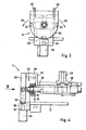
- In Fig. 1 ist mit 1 die Vorrichtung zum Bearbeiten von Stangenmaterial 10, Profilen oder dergleichen dargestellt. Die Vorrichtung 1 weist hierzu einen Maschinentisch 12 auf, auf dem die Profile 10 mit Hilfe der Profilhalterung 3 gelagert sind. An dem Tisch 12 ist auch das Bearbeitungsaggregat 6 vorgesehen. Das Bearbeitungsaggregat 6 ist zum Beispiel eine Hochgeschwindigkeitswerkzeugspindel, ein Fräser, ein Bohrer, ein Hobel oder dergleichen. Das Bearbeitungsaggregat 6 ist parallel zur Längsachse 11 des Profiles 10 verschiebbar, in Richtung der X-Achse angeordnet. Gleichzeitig ist das Bearbeitungsaggregat auch in den beiden anderen Raumachsen, also der Y- und Z-Achse beweglich. Dadurch wird eine Positionierung des Bearbeitungsaggregates 6 in der Höhe bzw. in der Tiefe erreicht. Das Bearbeitungsaggregat 6 ist beispielsweise auch schwenkbar ausgestaltet oder weist einen Winkelantrieb auf, um zum Beispiel die Stirnseite 13 des Profiles 10 zu bearbeiten.
- In Fig. 1 ist gezeigt, daß als Profilhalterung 3 eine zweigeteilte Welle 31,32 vorgesehen ist. Diese Zweiteilung der Welle hat den Vorteil, daß relativ kurze Wellen einfach herstellbar sind und eine Mehrzahl dieser Wellen eine lange Profilhalterung bilden. Dadurch wird eine große Flexibilität der Vorrichtung erreicht. Auch ist die Fertigung der kurzen Wellen einfacher und kostengünstiger. Eine Mehrzahl der Wellen ist hierbei so angeordnet, daß diese je in einer Flucht liegen.
- Die beiden Wellen 31,32 sind über den Aufspanntisch 36 miteinander starr verbunden.
- Auf dem Maschinentisch 12 sind mehrere Stützen 15 vorgesehen, die Lager 14 tragen, in denen die Welle 30 gelagert ist. Der Aufspanntisch 36 ist durch Stützlager 37 mit der Welle verbunden.
- Wie in Fig. 1 gezeigt, weist die Profilhalterung an ihren Enden je eine Arretierung 5 auf. Dadurch wird erreicht, daß die Profilhalterung 3, zum Beispiel die Welle 30, in der verschwenkten Stellung optimal gehalten wird.
- Die Einsatzmöglichkeit der Vorrichtung wird weiter erhöht, wenn beispielsweise vorgesehen wird, daß auf einem Maschinentisch 12 nicht nur eine Profilhalterung 3 vorgesehen ist, sondern eine Mehrzahl von Profilhalterungen. Hierbei wird zum Beispiel der Vorteil erreicht, daß ein Bearbeitungsaggregat 6 vorgesehen ist, das beispielsweise mit zwei Profilhalterungen 3 zusammenwirkt. Es ist nun zum Beispiel eine Bearbeitung derart möglich, daß zuerst an der rechten Profilhalterung das Profil gewechselt wird, während das Bearbeitungsaggregat 6 an dem Profil, das an der linken Profilhalterung vorgesehen ist, Bearbeitungen vornimmt. Die hohen Aufwendungen für eine Werkzeugspindel, insbesondere eine Hochgeschwindigkeitsspindel, werden somit mit der erfindungsgemäßen Vorrichtung optimal genützt.
- In Fig. 4 ist als Detail das Ende der Profilhalterung mit der Arretierung 5 gezeigt. Am Ende 33 der Welle 30 ist die Arretierung 5 vorgesehen. Die Arretierung 5 besteht aus einer Arretierscheibe 50, die auf das Ende der Welle 30 aufgesteckt ist. Die Arretierscheibe 50 ist zum Beispiel kreisrund ausgebildet. Es ist aber auch möglich, daß die Arretierscheibe 50 aus einer Halbscheibe besteht, in deren oberen Bereich 10 rechtwinklig zur Scheibe eine Strebe 58 oder ein Träger angeformt ist, wie es beispielsweise in Fig. 3 angedeutet ist. Bei einer solchen Ausgestaltung wirkt dann zum Beispiel die Arretierscheibe 50 noch als Anschlag 57 für das auf dem Aufspannschlitten 38 gehaltenen Profil 10, wobei die Strebe 58 den Anschlag 57 trägt.
- In einer weiteren Ausgestaltung ist es günstig, einen absenkbaren Anschlag vorzusehen, insbesondere dann, wenn eine stirnseitige Bearbeitung des Profiles erfolgen soll. Hierbei ist vorgesehen, daß die Auflageebene des Profiles auf der Spannvorrichtung über der Vorrichtung für die Arretierung, insbesondere der Arretierscheibe, angeordnet ist.
- Der Anschlag 57 ist durch eine Strebe 58 mit der Scheibe 50 verbunden. Mit der Strebe 58 übergreift der Anschlag 57 das Endlager 16 sowie die Stütze 15, in welchem die Welle 30 gelagert ist. Wie in Fig. 4 angedeutet, ist der Anschlag 57 fast auf der Welle 30 aufstehend ausgebildet. Durch eine solche Ausgestaltung des Anschlages in Verbindung mit der Strebe 58 wird auch der Abdeckeffekt für das Endlager 16 erreicht. Dies ist von Vorteil, da mit der erfindungsgemäßen Vorrichtung auch spanabhebende Bearbeitungen vorgenommen werden und somit ein Verschmutzen in diesem Bereich optimal vermieden werden kann.
- Erfindungsgemäß sind mehrere verschiedene Möglichkeiten für die Arretierung vorgesehen. Zunächst ist eine Arretierung durch einen in die Scheibe einführbaren Arretierstift 54 vorgesehen. Des weiteren ist vorgesehen, daß für eine stufenlose Einstellung ein Servomotor 22 als Verschwenkantrieb 20 vorgesehen ist, der eine entsprechende Bremse oder Kupplung aufweist, um die verschwenkte Profilhalterung in der gewünschten Stellung zu halten. Des weiteren kann vorgesehen sein, daß die Welle 30 bzw. die Profilhalterung 3 in ihrem Endbereich als Keilwelle ausgebildet ist, und diese Keilwelle durch entsprechende Arretierstellungen feststellbar ist.
- Bei der Ausbildung der Arretierung 5 durch eine Arretierscheibe 50 ist vorgesehen, daß die Scheibe 50 radiale Öffnungen 51,52, 53 aufweist, in die ein Arretierstift 54 einführbar ist. Der Arretierstift 54 wird von einem Arbeitszylinder 55 betätigt. Dies kann beispielsweise ein Pneumatikzylinder oder auch ein Elektroantrieb sein. Der Stift 54 bzw. der Arbeitszylinder 55 ist hierbei zum Beispiel am Maschinentisch vorgesehen. Der Stift 54 weist eine konische Spitze 56 auf. Dadurch wird das Einfahren des Stiftes 54 in die Öffnungen 51,52,53 erreicht und eine stabile, mechanische Verbindung zwischen der Scheibe und dem Maschinentisch 12 bewirkt.
- Erfindungsgemäß wird vorgeschlagen, daß der Abstand der Öffnungen 51,52 53 am Umfang der Scheibe 50 jeweils 90° beträgt. Mit einer solchen Ausgestaltung ist eine 3-Seitenbearbeitung des aufgespannten Profiles oder Stangenmaterials leicht möglich. Durch entsprechende Wahl der Öffnungen 51,52,53 bezüglich zusätzlicher Öffnungen ist es leicht möglich, jede andere Winkelverstellung zu realisieren. Auch ist eine axiale Arretierung vorstellbar, bei der die Anordnung des Stiftes 54 in Achsrichtung, zum Beispiel der Welle 30, erfolgt.
- Es ist auch vorgesehen, daß ein Servomotor 22 die Arretierung 5 bildet. Eine solche Ausgestaltung ist insbesondere dann von Vorteil, wenn verschiedene Winkeleinstellungen gewünscht werden. Der Servomotor 22 ist dann zum Beispiel an beiden Enden der Profilhalterung 3 vorgesehen, um diesen optimal zu halten. Der Servomotor 22 weist eine Kupplung oder Bremse auf, um die Stellung sicher zu arretieren. Für einen gleichmäßigen Antrieb der Verschwenkbewegung der Profilhalterung 3 ist vorgesehen, daß die Steuerung auf die an der Profilhalterung angreifenden Servomotoren gemeinsam wirkt, so daß eine gleichförmige Bewegung und Arretierung dieser Servomotoren sichergestellt ist.
- In Fig. 4 ist der Aufspannschlitten 38 gezeigt, der auf der Welle 30 angeordnet ist. Der Aufspannschlitten 38 ist auf der Welle 30 festgeklemmt, so daß eine Verschwenkung der Welle 30 auch zu einer Verschwenkung des Aufspannschlittens 38 führt. Der Aufspannschlitten 38 stützt sich über das Linearlager 39 auf der Welle 30 ab. Hierdurch können die Aufspannschlitten 38 auf der Führungswelle 30 händisch oder pneumatisch verschoben und auf der Welle 30 in beliebiger Position fixiert werden. Dies ist insbesondere dann von Vorteil, wenn eine Profilbearbeitung an Stellen vorgenommen werden soll, die durch die Spannbacken 40 verdeckt sind.
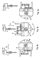
- In den Fig. 5a, 5b und 5c ist die erfindungsgemäße Vorrichtung in drei verschiedenen, geschwenkten Stellungen gezeigt. Die Verschwenkvorrichtung 2 bewirkt ein Verschwenken der Profilhalterung 3 um eine Achse, die parallel zur Längsachse des Stangenmaterials 10 ist. Die Profilhalterung 3 wird um die Achse 34 der Welle 30 geschwenkt. Die Verschwenkbewegung ist mit dem Pfeil 25 angedeutet. An den Profilen 10 werden mit dem Bearbeitungsaggregat 6 Bearbeitungen durchgeführt. Das Bearbeitungsaggregat 6 weist eine Beweglichkeit mindestens in den drei Raumachsen X, Y und Z auf. Die X-Achse (Doppelpfeil 62) wird hierbei beschrieben durch die Ausrichtung der Achse 34 bzw. der Längsachse 11 des Stangenmaterials 10. Die Y-Achse ist die waagrechte Senkrechte zur X-Achse. Die Y-Achse ist durch den Doppelpfeil 60 angedeutet. Durch die Beweglichkeit in Z-Richtung (Pfeil 61) ist eine Höheneinstellung leicht möglich. In Fig. 5c ist gezeigt, daß in Bezug auf die Stellung in Fig. 5a das Bearbeitungsaggregat 6 gegenüber der Achse 34 nach rechts verschoben ist.
- Für eine Bewegung des Bearbeitungsaggregates 6 in den drei Raumachsen X (62), Y (60) und Z (61) ist eine Positioniereinheit 7 vorgesehen. Diese Positioniereinheit 7 besteht aus einer Schienenbahn 70, die im wesentlichen parallel zur Längsachse 34 der Welle 30 der Profilhalterung 3 angeordnet ist. Auf dieser Schienenbahn 70 ist ein Schlitten 71 vorgesehen, der das Bearbeitungsaggregat 6 trägt. In dem Schlitten 71 ist der Antrieb für das Bearbeitungsaggregat 6 vorgesehen sowie eine Höhenverstellung (Z-Achse) für das Bearbeitungsaggregat bzw. eine Verstellbarkeit (Y-Achse) quer zur Längsachse 34 der Welle 30. Die Positioniereinheit 7, die über dem Bearbeitungstisch 12 angeordnet ist, kann aber auch quer zur Längserstreckung des Profiles verschiebbar bzw. verfahrbar angeordnet sein. Die Schienenbahn 70 ist auf einer Strebe 72 gehalten, wobei das Bearbeitungsaggregat 6 zum Beispiel von oben das Profil bearbeitet. An der Strebe 72 ist auch vorgesehen, daß ein weiteres Bearbeitungsaggregat 65 wahlweise eingesetzt wird, um beispielsweise die Stirnfläche des Profiles zu bearbeiten. Das Bearbeitungsaggregat 65 weist wahlweise einen Vortrieb in X-Richtung (62) auf.
- Eine solche Ausrichtung bereitet keine Schwierigkeiten, da das Bearbeitungsaggregat 6 in der Regel mindestens eine 3-Achsenwerkzeugspindel ist. Durch die erfindungsgemäße Ausgestaltung wird jedoch erreicht, daß auf eine aufwendigere Beweglichkeit der Werkzeugspindel bezüglich einer möglichst vielseitigen Bearbeitung des Stangenmaterials verzichtet werden kann.
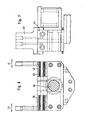
- In Fig. 6 ist in teilweisem Schnitt die Profilspannvorrichtung 35 gezeigt. Die Profilspannvorrichtung 35 ist auf der Welle 30 angeordnet. Zum Festklemmen des Profiles 10 sind Spannbacken 40,45 vorgesehen, die das Profil an der Seite zangenartig ergreifen.
- Bei einer zentrischen Spannung des Profiles ist vorgesehen, daß die Spannbacken 40,45 eine gleichförmige Bewegung ausführen. Für den Antrieb der beiden Spannbacken 40, deren Bewegung mit dem Doppelpfeil 41 angedeutet ist, ist ein gemeinsamer Antrieb vorgesehen.
- Hierbei greift zum Beispiel ein pneumatisch oder hydraulisch beaufschlagter Zylinder an einer Zugplatte an. Diese Zugplatte weist eine Kulissenführung für die beiden Spannbacken 40,45 auf. Je ein Kulissenstein, der mit der Spannbacke verbunden ist, greift in die jeweilige Kulissenführung ein. Bei einer Beaufschlagung des Arbeitszylinders erfolgt eine Bewegung der Zugplatte, und daraus resultieren die Bewegungen entsprechend dem Pfeil 41 der Spannbacken 40,45. Für die Bewegung der Spannbacken 40,45 ist eine Lagerung der Spannbacken 40,45 auf dem Spannsattel 42 vorgesehen. Das Lager hierzu ist mit 43 gekennzeichnet.
- Um unterschiedliche Profilstärken bearbeiten zu können ist vorgesehen, daß die Spannbacken 40 in verschiedenen Grundstellungen einsetzbar sind. Hierzu sitzen die Spannbacken 40 auf einem Einstellschlitten, und der Einstellschlitten weist die Kulisse für die Kulissenführung auf. Die Spannbacken werden zum Beispiel mit Schrauben auf dem Einstellschlitten gesichert. Der Einstellschlitten weist Einrastungen auf, die in einem kürzeren Abstand vorgesehen sind als der maximale Spannbereich der Spannbacken. Dadurch kann jede beliebige Profilstärke zwischen einem minimalen und maximalen Maß gehalten werden. Die Spannbacken werden beispielsweise pneumatisch oder hydraulisch beaufschlagt. Die Beaufschlagung erfolgt zum Beispiel an dem genannten Arbeitszylinder. Eine pneumatische Beaufschlagung kann beispielsweise beim Festhalten von Kunststoffprofilen ausreichend sein, da bei dieser Bearbeitung die auftretenden Kräfte geringer sind als bei einer Metallbearbeitung. Bei hohen Beanspruchungen ist zum Beispiel vorgesehen, daß eine hydraulische Beaufschlagung stattfindet. Der Arbeitszylinder ist hierbei beidseitig beaufschlagbar, eine Bewegung der Spannbacken in die Feststell- oder Lösrichtung wird jeweils durch den Arbeitszylinder betätigt.
- Als Verschwenkantrieb 20 ist zum Beispiel auch ein Getriebemotor 23 vorgesehen, der über einen Zahnriemen oder Keilriemen 24 auf die Welle 30 wirkt.
- Für die Überwachung der Bewegung des Bearbeitungsaggregates 6 ist eine Steuerung 8 vorgesehen. Das Bearbeitungsaggregat 6 ist hierbei über die Datenleitung 81 mit der Steuerung 8 verbunden. Die Steuerung 8 bestimmt hierbei die Bearbeitungsposition, also die Koordinaten entlang der Bewegungsachsen, hier also den drei Raumachsen. Des weiteren ist die Steuerung 8 mit dem Verschwenkantrieb 20, also dem Servomotor 22 oder dem Getriebemotor 23, verbunden und regelt die Verdrehung des Profiles. Mit der Datenleitung 82 ist die Arretierung 5 mit der Steuerung 8 verbunden. Vor einem Verdrehen des Profiles für eine neue Bearbeitung wird über diese Datenleitung die Arretierung gelöst, damit die Verschwenkvorrichtung 2 das Profil 10 verschwenken kann. Wenn die Verschwenkung abgeschlossen ist, kann die Arretierung wieder geschlossen werden bzw. bei der Verwendung eines Servomotores 22 eine entsprechende Bremse oder Kupplung betätigt werden. Die Steuerung 8 berücksichtigt bei einem verschwenkten Profil die neuen Arbeitskoordinaten, da zum Beispiel die Steuerung die Dimension des Profils, sowie den Drehwinkel kennt und diese Information zu den Bearbeitungskoordinaten an dem Profil sinngemäß hinzunimmt und so die neue Bearbeitungsposition der Werkzeugspindel oder dergleichen bestimmt.
- In einer weiteren Ausgestaltung der Erfindung ist vorgesehen, daß die Vorrichtung einen Bearbeitungstisch aufweist und die Verschwenkvorrichtung auf dem Bearbeitungstisch montierbar ist. Durch eine solche Ausgestaltung ist es möglich, bestehende Werkzeugmaschinen, Bearbeitungszentren oder Vorrichtungen wie beschrieben in einfacher Weise sehr effektiv im Hinblick auf deren Einsetzbarkeit zu erweitern. Die Verschwenkvorrichtung wird zum Beispiel auf der Grundplatte des Bearbeitungstisches montiert. Hierbei weist die Verschwenkvorrichtung zum Beispiel Anschlüsse für Energie- und Steuerleitungen auf, wodurch eine problemlose Integrierung in die Vorrichtung möglich ist. Über die Steuerleitung werden zum Beispiel die Signale für die Verdrehung des Profils übermittelt.
- Es ist eine Verdrehbarkeit des Profils von bis zu 360° vorgesehen.
Claims (11)
- Vorrichtung zum Bearbeiten von einer Längsachse aufweisenden Profilen, wie Stangenmaterial (10) oder dergleichen, bestehend aus einer Bearbeitungseinheit (6) und einer das Profil (10) aufnehmenden Profilhalterung (3), wobei die Profilhalterung um eine Achse, die parallel zur Längsachse (11) des Profils (10) angeordnet ist schwenkbar ist, wobei die Profilhalterung (3) aus einer Welle (30) mit wenigstens einer daran angeordneten Profilspannvorrichtung (35) besteht, die Welle (30) die Profil trägt und die Welle aus mehreren Teilen, insbesondere zweigeteilt ist dadurch gekennzeichnet, daß zwei Wellen (31,32) durch einen Aufspanntisch (36) verbunden sind.
- Vorrichtung nach Anspruch 1, dadurch gekennzeichnet, daß die Vorrichtung eine Arretierung (5) aufweist, die die Profilhalterung (3) arretiert.
- Vorrichtung nach einem der vorhergehenden Ansprüche, dadurch gekennzeichnet, daß als Arretierung (5) eine Arretierscheibe (50) mit Öffnungen (51,52,53) vorgesehen ist, in die ein Arretierstift (54) einführbar ist.
- Vorrichtung nach einem der vorhergehenden Ansprüche, dadurch gekennzeichnet, daß die Arretierung (5) am Ende (33) der Welle (10) vorgesehen ist.
- Vorrichtung nach einem der Ansprüche 3 und 4, dadurch gekennzeichnet, daß die Öffnungen (51,52,53) in einem Abstand von 90 ° zueinander angeordnet sind.
- Vorrichtung nach einem der vorhergehenden Ansprüche, dadurch gekennzeichnet, daß als Verschwenkantrieb (20) ein Servomotor (22) vorgesehen ist.
- Vorrichtung nach einem der vorhergehenden Ansprüche, dadurch gekennzeichnet, daß ein Bearbeitungsaggregat (6) an der Vorrichtung vorgesehen ist, das die Seiten und/oder die Stirnfläche (13) des Profils (10) bearbeitet, wobei das Bearbeitungsaggregat (6) parallel und/oder in einer Ebene, die im wesentlichen rechtwinklig zur Längsachse (11) des Profils (10) angeordnet ist, bewegbar ist.
- Vorrichtung nach einem der vorhergehenden Ansprüche, dadurch gekennzeichnet, daß die Profilspannvorrichtung (35) einen Aufspannschlitten (38) aufweist, der längs der Welle (30) bewegbar ist.
- Vorrichtung nach einem der vorhergehenden Ansprüche, dadurch gekennzeichnet, daß die Profilspannvorrichtung (35) Spannbacken (40) aufweist, die pneumatisch, hydraulisch oder elektrisch betätigbar sind und das Profil (10) zangenartig an der Seite halten.
- Vorrichtung nach einem der vorhergehenden Ansprüche, dadurch gekennzeichnet, daß beide Spannbacken (40) eine gleiche Spannbewegung (41) für das zentrische Festspannen des Profiles (10) ausführen.
- Vorrichtung nach einem der vorhergehenden Ansprüche, dadurch gekennzeichnet, daß die Vorrichtung einen Bearbeitungstisch aufweist, und die Verschwenkvorrichtung auf dem Bearbeitungstisch montierbar ist.
Applications Claiming Priority (2)
| Application Number | Priority Date | Filing Date | Title |
|---|---|---|---|
| DE29601808U | 1996-02-04 | ||
| DE29601808U DE29601808U1 (de) | 1996-02-04 | 1996-02-04 | Vorrichtung zum Bearbeiten von Stangenmaterial, Profilen u.dgl. |
Publications (3)
| Publication Number | Publication Date |
|---|---|
| EP0787560A1 EP0787560A1 (de) | 1997-08-06 |
| EP0787560B1 EP0787560B1 (de) | 2002-04-10 |
| EP0787560B2 true EP0787560B2 (de) | 2007-01-03 |
Family
ID=8018909
Family Applications (1)
| Application Number | Title | Priority Date | Filing Date |
|---|---|---|---|
| EP97100989A Expired - Lifetime EP0787560B2 (de) | 1996-02-04 | 1997-01-23 | Vorrichtung zum Bearbeiten von Stangenmaterial, Profilen und dergleichen |
Country Status (4)
| Country | Link |
|---|---|
| US (1) | US5957638A (de) |
| EP (1) | EP0787560B2 (de) |
| AT (1) | ATE215866T1 (de) |
| DE (2) | DE29601808U1 (de) |
Families Citing this family (9)
| Publication number | Priority date | Publication date | Assignee | Title |
|---|---|---|---|---|
| DE59906051D1 (de) * | 1998-02-05 | 2003-07-31 | Bernhard Eisenbach | Vorrichtung zur mehrseitigen Bearbeitung von Hohlprofilen |
| IT1313224B1 (it) * | 1999-07-02 | 2002-06-17 | Unifor Spa | Dispositivo di serraggio e di posizionamento di pezzi in lavorazionedi forma allungata e sottile. |
| US6823572B2 (en) * | 2000-02-01 | 2004-11-30 | Emmegi S.A., Luxembourg, Lugano Branch | System for carrying out mechanical workings |
| DE10030865B4 (de) * | 2000-06-23 | 2004-09-02 | Eisenbach, Bernhard, Dipl.-Ing. | Spanneinrichtung für Werkstücke, wie Fenster- oder Türprofile oder sonstige langgestreckte Profile |
| ITMO20030004A1 (it) * | 2003-01-13 | 2004-07-14 | Emmegi Spa | Macchina utensile. |
| EP1555084A1 (de) * | 2004-01-13 | 2005-07-20 | Mubea Systems, Société Anonyme | Werkzeugmaschine mit längsverfahrbaren Spannvorrichtungen mit eigenem Antrieb |
| CN109175452A (zh) * | 2018-10-22 | 2019-01-11 | 森鹤乐器股份有限公司 | 一种总档支架的加工设备 |
| CN111823023B (zh) * | 2020-08-28 | 2025-02-07 | 焦作市强信粉末冶金科技有限公司 | 一种三维旋转工装 |
| CN119819968A (zh) * | 2025-03-17 | 2025-04-15 | 浙江品峰机械有限公司 | 不锈钢烘板加工用矫正穿孔设备及方法 |
Citations (1)
| Publication number | Priority date | Publication date | Assignee | Title |
|---|---|---|---|---|
| US4502457A (en) † | 1982-08-27 | 1985-03-05 | Raul C. Montoya | Universal multiple angle work piece holder with multiple tool conversion features |
Family Cites Families (11)
| Publication number | Priority date | Publication date | Assignee | Title |
|---|---|---|---|---|
| DE245103C (de) * | ||||
| US1498660A (en) * | 1919-12-29 | 1924-06-24 | Columbia Axle Company | Work-holding mechanism |
| US2651975A (en) * | 1949-05-11 | 1953-09-15 | Soloff Milton | Internal carving machine |
| US3371580A (en) * | 1966-01-21 | 1968-03-05 | Mc Donnell Douglas Corp | Multiple axis milling machine and fixture |
| US3746459A (en) * | 1971-03-24 | 1973-07-17 | Overmyer Mould Co | Apparatus for drilling escape and vent holes in die molds |
| US3918145A (en) * | 1974-07-08 | 1975-11-11 | Frank R Oglivie | Automatic machine tool |
| DE2915380A1 (de) * | 1979-04-14 | 1980-10-16 | Hegenscheidt Gmbh Wilhelm | Verfahren zum einspannen rohrfoermiger werkstuecke auf tiefbohrmaschinen |
| FR2540023B1 (fr) * | 1983-02-01 | 1986-07-25 | Dufieux Machine Outil | Dispositif destine a deplacer, devant des moyens d'usinage et dans le sens de sa longueur, un profile a usiner |
| JPS61288908A (ja) * | 1985-06-14 | 1986-12-19 | Hidetoshi Okawa | 中空材木の製造装置 |
| CA2012117C (en) * | 1990-02-12 | 2001-05-01 | John Ingvar Emanuel Johansson | A manipulator intended for cooperation with an industrial robot |
| DE4204519A1 (de) * | 1992-02-15 | 1993-08-19 | Bernhard Eisenbach | Vorrichtung zur mehrseitigen bearbeitung von hohlprofilen |
-
1996
- 1996-02-04 DE DE29601808U patent/DE29601808U1/de not_active Expired - Lifetime
-
1997
- 1997-01-23 EP EP97100989A patent/EP0787560B2/de not_active Expired - Lifetime
- 1997-01-23 DE DE59706922T patent/DE59706922D1/de not_active Expired - Fee Related
- 1997-01-23 AT AT97100989T patent/ATE215866T1/de not_active IP Right Cessation
- 1997-02-04 US US08/795,310 patent/US5957638A/en not_active Expired - Fee Related
Patent Citations (1)
| Publication number | Priority date | Publication date | Assignee | Title |
|---|---|---|---|---|
| US4502457A (en) † | 1982-08-27 | 1985-03-05 | Raul C. Montoya | Universal multiple angle work piece holder with multiple tool conversion features |
Non-Patent Citations (3)
| Title |
|---|
| Prospekt Matec 30-L † |
| Prospekt NIKKEN LOCK-JAW SAX-4MT-120 † |
| Prospekt Tekna TK 426 † |
Also Published As
| Publication number | Publication date |
|---|---|
| EP0787560A1 (de) | 1997-08-06 |
| EP0787560B1 (de) | 2002-04-10 |
| ATE215866T1 (de) | 2002-04-15 |
| DE29601808U1 (de) | 1996-04-11 |
| US5957638A (en) | 1999-09-28 |
| DE59706922D1 (de) | 2002-05-16 |
Similar Documents
| Publication | Publication Date | Title |
|---|---|---|
| EP1188511B1 (de) | Werkzeugmaschine mit einem motorisch fahrbaren Werkzeugschlitten | |
| DE4113629C2 (de) | Reihenbohr- und Fräsmaschine | |
| CH629407A5 (de) | Werkzeugmaschine. | |
| EP0130309B1 (de) | Holzbearbeitungsmaschinen | |
| DE19919645A1 (de) | Werkzeugmaschine mit Werkzeugspindel und Revolverkopf | |
| EP1286794B1 (de) | Kaltwalzmaschine | |
| EP0787560B2 (de) | Vorrichtung zum Bearbeiten von Stangenmaterial, Profilen und dergleichen | |
| EP2425921A2 (de) | Vorrichtung zur Bearbeitung von Werkstücken | |
| DE19516263A1 (de) | CNC-gesteuerte Holzbearbeitungsanlage, insbesondere für lange Werkstücke wie Balken | |
| EP1651381B1 (de) | Werkzeugmaschine mit einspannvorrichtung auf beiden seiten | |
| DE69126135T2 (de) | Portalwerkzeugmaschine | |
| DE10330909B4 (de) | Werkzeugmaschine und Verfahren zur spanabhebenden Bearbeitung von Werkstücken | |
| EP1025953A1 (de) | Werkzeugmaschine | |
| DE20010717U1 (de) | Multifunktionale Bohrmaschine | |
| DE19911156C2 (de) | Drehmaschine zur Bearbeitung von wellenförmigen Werkstücken | |
| DE2636986A1 (de) | Drehbank | |
| AT521951B1 (de) | Werkzeugmaschine | |
| DE10145674B4 (de) | Werkzeugmaschine zur Bearbeitung eines stangenförmigen Werkstücks | |
| EP0813941B2 (de) | Abbundanlage zur Bearbeitung von Strangmaterial | |
| DE19831284C2 (de) | Abbundanlage zur Bearbeitung von Strangmaterial | |
| EP1577040A1 (de) | Vorrichtung zum Bearbeiten von Werkstücken, insbesondere von mit Schneidzähnen versehenen Werkstücken | |
| DE8912243U1 (de) | Kurzhub-Werkzeugmaschine mit einem an einem Maschinengestell verfahrbar gelagerten Bohr- und Frässpindelstock | |
| DE9006627U1 (de) | Werkzeugmaschine | |
| DE9007396U1 (de) | Werkzeugmaschine | |
| DE952583C (de) | Fraesmaschine, insbesondere zum Herstellen von Profillehren |
Legal Events
| Date | Code | Title | Description |
|---|---|---|---|
| PUAI | Public reference made under article 153(3) epc to a published international application that has entered the european phase |
Free format text: ORIGINAL CODE: 0009012 |
|
| AK | Designated contracting states |
Kind code of ref document: A1 Designated state(s): AT DE FR GB IT |
|
| 17P | Request for examination filed |
Effective date: 19971015 |
|
| 17Q | First examination report despatched |
Effective date: 20000518 |
|
| GRAG | Despatch of communication of intention to grant |
Free format text: ORIGINAL CODE: EPIDOS AGRA |
|
| GRAG | Despatch of communication of intention to grant |
Free format text: ORIGINAL CODE: EPIDOS AGRA |
|
| GRAH | Despatch of communication of intention to grant a patent |
Free format text: ORIGINAL CODE: EPIDOS IGRA |
|
| REG | Reference to a national code |
Ref country code: GB Ref legal event code: IF02 |
|
| GRAH | Despatch of communication of intention to grant a patent |
Free format text: ORIGINAL CODE: EPIDOS IGRA |
|
| GRAA | (expected) grant |
Free format text: ORIGINAL CODE: 0009210 |
|
| AK | Designated contracting states |
Kind code of ref document: B1 Designated state(s): AT DE FR GB IT |
|
| REF | Corresponds to: |
Ref document number: 215866 Country of ref document: AT Date of ref document: 20020415 Kind code of ref document: T |
|
| REF | Corresponds to: |
Ref document number: 59706922 Country of ref document: DE Date of ref document: 20020516 |
|
| GBT | Gb: translation of ep patent filed (gb section 77(6)(a)/1977) |
Effective date: 20020702 |
|
| ET | Fr: translation filed | ||
| PLBQ | Unpublished change to opponent data |
Free format text: ORIGINAL CODE: EPIDOS OPPO |
|
| PLBI | Opposition filed |
Free format text: ORIGINAL CODE: 0009260 |
|
| PLBF | Reply of patent proprietor to notice(s) of opposition |
Free format text: ORIGINAL CODE: EPIDOS OBSO |
|
| 26 | Opposition filed |
Opponent name: TEKNA S.R.L Effective date: 20030107 |
|
| PLAX | Notice of opposition and request to file observation + time limit sent |
Free format text: ORIGINAL CODE: EPIDOSNOBS2 |
|
| PLBB | Reply of patent proprietor to notice(s) of opposition received |
Free format text: ORIGINAL CODE: EPIDOSNOBS3 |
|
| PUAH | Patent maintained in amended form |
Free format text: ORIGINAL CODE: 0009272 |
|
| STAA | Information on the status of an ep patent application or granted ep patent |
Free format text: STATUS: PATENT MAINTAINED AS AMENDED |
|
| 27A | Patent maintained in amended form |
Effective date: 20070103 |
|
| AK | Designated contracting states |
Kind code of ref document: B2 Designated state(s): AT DE FR GB IT |
|
| GBTA | Gb: translation of amended ep patent filed (gb section 77(6)(b)/1977) | ||
| PGFP | Annual fee paid to national office [announced via postgrant information from national office to epo] |
Ref country code: DE Payment date: 20070321 Year of fee payment: 11 |
|
| ET3 | Fr: translation filed ** decision concerning opposition | ||
| PGFP | Annual fee paid to national office [announced via postgrant information from national office to epo] |
Ref country code: GB Payment date: 20080123 Year of fee payment: 12 Ref country code: IT Payment date: 20080126 Year of fee payment: 12 |
|
| PGFP | Annual fee paid to national office [announced via postgrant information from national office to epo] |
Ref country code: AT Payment date: 20080111 Year of fee payment: 12 |
|
| PGFP | Annual fee paid to national office [announced via postgrant information from national office to epo] |
Ref country code: FR Payment date: 20080118 Year of fee payment: 12 |
|
| PG25 | Lapsed in a contracting state [announced via postgrant information from national office to epo] |
Ref country code: DE Free format text: LAPSE BECAUSE OF NON-PAYMENT OF DUE FEES Effective date: 20080801 |
|
| PLAB | Opposition data, opponent's data or that of the opponent's representative modified |
Free format text: ORIGINAL CODE: 0009299OPPO |
|
| GBPC | Gb: european patent ceased through non-payment of renewal fee |
Effective date: 20090123 |
|
| PG25 | Lapsed in a contracting state [announced via postgrant information from national office to epo] |
Ref country code: AT Free format text: LAPSE BECAUSE OF NON-PAYMENT OF DUE FEES Effective date: 20090123 |
|
| REG | Reference to a national code |
Ref country code: FR Ref legal event code: ST Effective date: 20091030 |
|
| PG25 | Lapsed in a contracting state [announced via postgrant information from national office to epo] |
Ref country code: GB Free format text: LAPSE BECAUSE OF NON-PAYMENT OF DUE FEES Effective date: 20090123 |
|
| PG25 | Lapsed in a contracting state [announced via postgrant information from national office to epo] |
Ref country code: FR Free format text: LAPSE BECAUSE OF NON-PAYMENT OF DUE FEES Effective date: 20090202 |
|
| PG25 | Lapsed in a contracting state [announced via postgrant information from national office to epo] |
Ref country code: IT Free format text: LAPSE BECAUSE OF NON-PAYMENT OF DUE FEES Effective date: 20090123 |