EP0787509A2 - Support device for a basketball backboard, and court and sports hall with such a device - Google Patents
Support device for a basketball backboard, and court and sports hall with such a device Download PDFInfo
- Publication number
- EP0787509A2 EP0787509A2 EP97420019A EP97420019A EP0787509A2 EP 0787509 A2 EP0787509 A2 EP 0787509A2 EP 97420019 A EP97420019 A EP 97420019A EP 97420019 A EP97420019 A EP 97420019A EP 0787509 A2 EP0787509 A2 EP 0787509A2
- Authority
- EP
- European Patent Office
- Prior art keywords
- panel
- base
- basketball
- arm
- backboard
- Prior art date
- Legal status (The legal status is an assumption and is not a legal conclusion. Google has not performed a legal analysis and makes no representation as to the accuracy of the status listed.)
- Withdrawn
Links
Images


Classifications
-
- A—HUMAN NECESSITIES
- A63—SPORTS; GAMES; AMUSEMENTS
- A63B—APPARATUS FOR PHYSICAL TRAINING, GYMNASTICS, SWIMMING, CLIMBING, OR FENCING; BALL GAMES; TRAINING EQUIPMENT
- A63B63/00—Targets or goals for ball games
- A63B63/08—Targets or goals for ball games with substantially horizontal opening for ball, e.g. for basketball
- A63B63/083—Targets or goals for ball games with substantially horizontal opening for ball, e.g. for basketball for basketball
-
- A—HUMAN NECESSITIES
- A63—SPORTS; GAMES; AMUSEMENTS
- A63B—APPARATUS FOR PHYSICAL TRAINING, GYMNASTICS, SWIMMING, CLIMBING, OR FENCING; BALL GAMES; TRAINING EQUIPMENT
- A63B2208/00—Characteristics or parameters related to the user or player
- A63B2208/12—Characteristics or parameters related to the user or player specially adapted for children
-
- A—HUMAN NECESSITIES
- A63—SPORTS; GAMES; AMUSEMENTS
- A63B—APPARATUS FOR PHYSICAL TRAINING, GYMNASTICS, SWIMMING, CLIMBING, OR FENCING; BALL GAMES; TRAINING EQUIPMENT
- A63B2225/00—Miscellaneous features of sport apparatus, devices or equipment
- A63B2225/09—Adjustable dimensions
- A63B2225/093—Height
Abstract
Description
L'invention a trait à un dispositif de supportage d'un panneau de basket-ball et à un terrain ou une salle de sport comprenant un tel dispositif.The invention relates to a device for supporting a basketball hoop and to a field or a sports hall comprising such a device.
Conformément aux règles édictées par les différentes fédérations nationales et internationales, un panneau de basket-ball doit être supporté dans une position déterminée par rapport au terrain sur lequel évoluent les joueurs. Cette position est en particulier déterminée par la hauteur du cercle du panier qui doit être sensiblement de 3,05 m et par l'aplomb de la face avant du panneau par rapport à la ligne de fond du terrain qui doit être sensiblement de 1,20 m.In accordance with the rules decreed by the various national and international federations, a basketball board must be supported in a determined position relative to the ground on which the players play. This position is in particular determined by the height of the basket circle which must be approximately 3.05 m and by the vertical alignment of the front face of the panel with respect to the bottom line of the terrain which must be approximately 1.20 m.
Or, le basket se pratique dès le plus jeune âge, c'est-à-dire en particulier pour des enfants de 7 à 11 ans évoluant dans les catégories mini-poussins et poussins. Pour ces jeunes enfants, les règles du basket ont été aménagées et de nouvelles règles du jeu, appelées "mini-basket", ont été définies. Il a été convenu que le cercle du panier doit se trouver à 2,60 m de hauteur et que l'aplomb du panneau est porté à 1,80 m par rapport à la ligne de fond du terrain. Ceci permet à ces enfants de jouer sur le même terrain que les joueurs plus âgés, ce qui évite de définir plusieurs aires de jeux sur le sol d'un terrain de basket.However, basketball is practiced from an early age, that is to say in particular for children from 7 to 11 years old evolving in the mini-chicks and chicks categories. For these young children, the rules of basketball have been adapted and new rules of the game, called "mini-basketball", have been defined. It has been agreed that the circle of the basket must be 2.60 m high and that the plumb of the panel is increased to 1.80 m from the baseline of the field. This allows these children to play on the same field as the older players, which avoids defining several play areas on the ground of a basketball court.
Lorsque de jeunes enfants doivent jouer sur le terrain, il est donc nécessaire d'installer des panneaux conformes aux règles du mini-basket. Selon un dispositif connu de l'art antérieur, on peut accrocher un second panneau sur le panneau existant pour les joueurs adultes, ce second panneau étant décalé vers l'avant et vers le bas afin d'être accessible aux jeunes joueurs. Cependant, l'accrochage du second panneau n'est pas parfait et il peut être plus ou moins dangereux car il risque de se décrocher s'il est soumis à des chocs violents ou à l'effet du vent. De plus, ce dispositif nécessite la manoeuvre en hauteur d'un second panneau dont le poids peut atteindre 10 à 15 kg, ce qui implique l'intervention d'un ou de plusieurs adultes pour sa mise en place.When young children have to play on the ground, it is therefore necessary to install signs that comply with the rules of mini-basketball. According to a device known from the prior art, a second panel can be hung on the existing panel for adult players, this second panel being shifted forward and downward so as to be accessible to young players. However, the attachment of the second panel is not perfect and it can be more or less dangerous because it may fall off if it is subjected to strong shocks or to the effect of the wind. In addition, this device requires the operation in height of a second panel whose weight can reach 10 to 15 kg, which implies the intervention of one or more adults for its installation.
Il est aussi possible de prévoir une structure mobile, par exemple sur roulettes, supportant un panneau à hauteur adéquate pour le mini-basket, cette structure étant mise en place sur le terrain en cas de nécessité. Dans ce cas, il est nécessaire de prévoir un système d'amarrage sur le terrain, ce qui modifie l'état de surface de ce dernier. En outre, il faut prévoir un système de rangement, en particulier hors de portée des jeunes enfants pour que cette structure mobile ne soit pas dangereuse lorsqu'elle n'est pas utilisée.It is also possible to provide a mobile structure, for example on casters, supporting a panel at an adequate height for the mini-basketball, this structure being placed on the land if necessary. In this case, it is necessary to provide a mooring system on the ground, which modifies the surface condition of the latter. In addition, a storage system must be provided, in particular out of reach of young children so that this mobile structure is not dangerous when it is not used.
Les dispositifs de l'art antérieur utilisent un panneau différent pour la pratique du mini-basket et pour la pratique du basket proprement dit, ce qui implique un investissement double pour les municipalités ou les associations en charge de ce sport.The devices of the prior art use a different panel for the practice of mini-basketball and for the practice of basketball itself, which implies a double investment for the municipalities or associations in charge of this sport.
Par ailleurs, on connaît de la demande WO-A-95/21659 un cadre pour panneau de basket-ball ajustable entre une position de jeu pour enfants et une position de jeu pour adultes au moyen d'une structure à parallélogramme. En position de jeu pour adultes, le panneau de basket-ball est instable dans la mesure où le cadre qui le supporte ne peut pas être plaqué contre l'embase fixe, car les bras constituant la structure à parallélogramme sont sensiblement rectilignes. Si les bras latéraux formant une structure à parallélogramme conforme à cet art antérieur ont une longueur suffisante pour permettre le passage de la position basket à la position mini-basket précédemment invoquées, ils interfèrent au point qu'ils gênent la mise en place du panneau en position de jeu pour adultes, c'est-à-dire en position haute. En d'autres termes, le panneau de basket est en permanence en porte-à-faux par rapport à l'embase sur lequel il est articulé, de sorte qu'il risque de bouger, en particulier lorsqu'un joueur adulte s'accroche sur le panier en cours de jeu.Furthermore, there is known from application WO-A-95/21659 a frame for an adjustable basketball panel between a play position for children and a play position for adults by means of a parallelogram structure. In the playing position for adults, the basketball panel is unstable insofar as the frame which supports it cannot be pressed against the fixed base, since the arms constituting the parallelogram structure are substantially rectilinear. If the lateral arms forming a parallelogram structure in accordance with this prior art have a length sufficient to allow the passage from the basket position to the mini-basketball position previously cited, they interfere to the point that they interfere with the positioning of the panel in adult play position, i.e. in the high position. In other words, the basketball hoop is permanently cantilevered with respect to the base on which it is hinged, so that it risks moving, in particular when an adult player hangs on on the basket during play.
C'est à ces inconvénients qu'entend plus particulièrement remédier l'invention en proposant un dispositif de supportage de panneau de basket permettant un positionnement adéquat de celui-ci en position de jeu pour adultes.It is to these drawbacks that the invention more particularly intends to remedy by proposing a support device for a basketball hoop allowing an adequate positioning thereof in the playing position for adults.
Dans cet esprit, l'invention concerne un dispositif de supportage d'un panneau d'un basket-ball comprenant une structure à parallélogramme, agencée entre le panneau et une embase, mobile entre deux positions correspondant à deux positions de jeu du panneau, caractérisé en ce que la structure à parallélogramme comprend une pluralité de bras formés de deux sections orientées obliquement l'une par rapport à l'autre.In this spirit, the invention relates to a device for supporting a panel of a basketball comprising a parallelogram structure, arranged between the panel and a base, movable between two positions corresponding to two playing positions of the panel, characterized in that the parallelogram structure includes a plurality of arms formed of two sections oriented obliquely to each other.
Grâce à l'invention, les bras formant la structure à parallélogramme ne s'opposent pas au rapprochement du panneau de basket par rapport à l'embase support et ce, quelle que soit leur longueur.Thanks to the invention, the arms forming the parallelogram structure do not oppose the approximation of the basketball hoop relative to the support base and this, whatever their length.
Selon un premier aspect avantageux de l'invention, la section reliée au panneau d'un bras inférieur de la structure à parallélogramme et la section reliée à l'embase d'un bras supérieur sont parallèles lorsque le panneau est dans sa position haute. Grâce à cet aspect de l'invention, la forme des bras de la structure à parallélogramme est particulièrement adaptée à un positionnement compact de cette structure lorsque le panneau est en position haute.According to a first advantageous aspect of the invention, the section connected to the panel of a lower arm of the parallelogram structure and the section connected to the base of an upper arm are parallel when the panel is in its high position. Thanks to this aspect of the invention, the shape of the arms of the parallelogram structure is particularly suitable for compact positioning of this structure when the panel is in the high position.
Selon un autre aspect avantageux de l'invention, le dispositif comprend deux élingues définissant la distance maximum d'éléments respectivement solidaires du panneau et de l'embase. Ces élingues servent à limiter la course du panneau vers le bas et constituent des éléments porteurs et des éléments de sécurité pour le dispositif.According to another advantageous aspect of the invention, the device comprises two slings defining the maximum distance of elements respectively secured to the panel and the base. These slings serve to limit the downward travel of the panel and constitute load-bearing elements and safety elements for the device.
Selon un mode de réalisation avantageux de l'invention, le dispositif comprend en outre un bras de manoeuvre cinématiquement relié au panneau et à l'embase, ce bras de manoeuvre étant apte à déplacer le panneau par rapport à l'embase. Un levier de manoeuvre peut être fixé de façon amovible sur le bras de manoeuvre et permet le déplacement du panneau, entre ces deux positions, par un utilisateur situé au sol.According to an advantageous embodiment of the invention, the device further comprises an operating arm kinematically connected to the panel and to the base, this operating arm being able to move the panel relative to the base. An operating lever can be removably attached to the operating arm and allows the panel to be moved between these two positions by a user located on the ground.
En outre, selon un autre aspect de l'invention, des moyens de rappel de la structure à parallélogramme dans une des deux positions, par exemple dans sa position haute, permettent aussi de garantir une bonne stabilité mécanique du dispositif.In addition, according to another aspect of the invention, means for returning the parallelogram structure to one of the two positions, for example in its high position, also make it possible to guarantee good mechanical stability of the device.
Un moyen de verrouillage de la structure à parallélogramme dans une de ses positions peut être prévu, ce moyen de verrouillage pouvant être un raidisseur formé de deux sections articulées l'une par rapport à l'autre. En outre, le moyen de verrouillage peut être commandé par le levier de manoeuvre.Means for locking the parallelogram structure in one of its positions may be provided, this locking means possibly being a stiffener formed by two sections articulated with respect to each other. In addition, the locking means can be controlled by the operating lever.
Selon un autre aspect avantageux de l'invention correspondant à un mode de réalisation particulier de celle-ci, l'embase porte un mécanisme d'enroulement de brins de câble dont l'extrémité est solidaire du panneau. Cet aspect de l'invention permet une manoeuvre efficace et précise du panneau grâce à une manivelle.According to another advantageous aspect of the invention corresponding to a particular embodiment thereof, the base carries a cable strand winding mechanism, the end of which is secured to the panel. This aspect of the invention allows efficient and precise maneuvering of the panel by means of a crank.
Selon un autre aspect avantageux de l'invention, le dispositif comprend des moyens de butée à accumulation d'énergie disposés entre le panneau et l'embase, ces moyens de butée étant comprimés lorsque le panneau est dans sa position haute. Ces moyens de butées servent en particulier à amorcer le mouvement de descente du panneau à partir de sa position haute.According to another advantageous aspect of the invention, the device comprises energy storage abutment means arranged between the panel and the base, these abutment means being compressed when the panel is in its high position. These stop means serve in particular to initiate the downward movement of the panel from its high position.
L'invention concerne enfin un terrain de sport comprenant un dispositif conforme à l'invention.The invention finally relates to a sports field comprising a device according to the invention.
L'invention sera mieux comprise et d'autres avantages de celle-ci apparaîtront plus clairement à la lumière de la description qui va suivre de trois modes de réalisation d'un dispositif de supportage d'un panneau de basket-ball conforme à son principe, donnée uniquement à titre d'exemple et faite en référence aux dessins annexés dans lesquels :
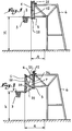
- la figure 1 est une vue de côté d'un panneau de basket-ball supporté par un dispositif conforme à l'invention dans une première position correspondant à la pratique du basket-ball ;
- la figure 2 est une vue analogue à la figure 1 alors que le panneau est dans la position correspondant à la pratique du mini-basket ;
- la figure 3 est une vue de côté à plus grande échelle, avec arrachement partiel, du panneau de basket-ball de la figure 1 et de son dispositif de supportage ;
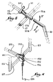
- la figure 4 est une vue en perspective du dispositif de supportage et du panneau dans la position de la figure 2 ;
- la figure 5 est une vue en perspective d'un détail du dispositif de l'invention ;
- la figure 6 est une vue de détail semblable à la figure 5 pour un second mode de réalisation de l'invention et
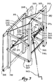
- la figure 7 est une vue analogue à la figure 4 pour un dispositif conforme à un troisième mode de réalisation de l'invention.
- Figure 1 is a side view of a basketball panel supported by a device according to the invention in a first position corresponding to the practice of basketball;
- Figure 2 is a view similar to Figure 1 while the panel is in the position corresponding to the practice of mini-basketball;
- Figure 3 is an enlarged side view, partially broken away, of the basketball backboard of Figure 1 and its support device;
- Figure 4 is a perspective view of the support device and the panel in the position of Figure 2;
- Figure 5 is a perspective view of a detail of the device of the invention;
- FIG. 6 is a detailed view similar to FIG. 5 for a second embodiment of the invention and
- Figure 7 is a view similar to Figure 4 for a device according to a third embodiment of the invention.
Le panneau 1 représenté à la figure 1 supporte un cercle métallique 2 auquel est accroché un panier 3, cet ensemble servant à la pratique du basket-ball.The
Le panneau 1 est maintenu dans une position déterminée par une structure 4, par exemple métallique, afin que le panier soit situé à une hauteur H de 3,05 m et que l'aplomb A de la face avant du panneau 1 par rapport à la ligne de fond du terrain de jeu soit de 1,20 m. Dans la position de la figure 2, le panneau a été déplacé de telle sorte que le cercle 2 est à une hauteur h de 2,60 m par rapport au sol et que la face avant du panneau 1 a un aplomb a de 1,80 m par rapport à la ligne de fond du terrain de jeu. Le déplacement du panneau 1 de la position de la figure 1 à la position de la figure 2 est possible grâce à une structure à parallélogramme qui apparaît plus clairement aux figures 3 et 4.The
Une embase 5 appartenant à la structure métallique 4 est reliée aux panneaux 1 par quatre bras 6, 7, 8 et 9 articulés dans des cornières en U 10, 11, 12 et 13. Les cornières 12 et 13 sont fixées par tout moyen adéquat sur l'embase 5, elles sont par exemple boulonnées ou soudées sur celle-ci. Par ailleurs, le panneau 1 est fixé par tout moyen adéquat, par exemple boulonné sur les cornières 10 et 11. Comme il apparaît en comparant les figures 3 et 4, la structure à parallélogramme formée par les éléments 6 à 13 est mobile entre deux positions correspondant aux deux positions de jeu représentées aux figures 1 et 2. Dans ces deux positions de jeu définies pour des joueurs de tailles et d'âges différents, un unique panneau 1 est utilisé.A
Conformément à l'invention, le bras 6 est constitué de deux sections 6a et 6b orientées obliquement l'une par rapport à l'autre alors que le bras 7 est aussi constitué de deux sections 7a et 7b orientées obliquement l'une par rapport à l'autre. Les angles d'orientation des sections 6a, 6b, 7a, 7b sont tels que les sections 7a et 6b sont parallèles lorsque le panneau est dans sa position haute telle que représentée à la figure 3, de sorte que la superposition des bras 6 et 7 ne perturbe pas le rapprochement du panneau 1 de l'embase 5. En d'autres termes, le pivotement du bras 7 par rapport à son axe d'articulation 7c n'est pas gêné par la partie inférieure du bras 6. Cette disposition des bras 6 et 7, qui est analogue à celle des bras 8 et 9, permet que la structure à parallélogramme soit compacte lorsqu'elle est dans la position de la figure 3, ce qui limite le porte-à-faux du panneau 1 par rapport aux axes d'articulation 6c et 7c des bras 6, 7 dans la cornière 12 lorsque le panneau est dans sa position haute. Ceci permet de conférer une bonne stabilité au panneau dans sa position haute.According to the invention, the
Le dispositif comporte en outre un bras de manoeuvre 15 articulé sur le panneau 1, par exemple au moyen d'une cornière en U 16 et monté libre en rotation sur l'une 17 des deux entretoises 17 et 18 reliant les cornières 12 et 13. Compte tenu de la fixation des cornières 12 et 13 sur l'embase 5, le bras de mouvement 15 est cinématiquement relié à l'embase 5.The device also comprises an
Un levier de manoeuvre 20 peut être adapté à l'extrémité 15a du bras de mouvement 15 distante du panneau 1 de façon à permettre à un utilisateur d'exercer un couple F ou F' destiné à faire pivoter le bras de mouvement 15 autour de son axe d'articulation sur l'entretoise 17. Le levier 20 pénètre à l'intérieur de l'extrémité 15a du bras de manoeuvre 15. Plus spécifiquement, dans la position de la figure 4, si un utilisateur exerce sur le levier 20 un effort tel qu'un couple F' est exercé sur le bras de mouvement 15, le panneau 1 est relevé vers sa position de la figure 3 et le bras de mouvement 15 est placé dans une position sensiblement verticale. A l'inverse, si un couple F est exercé sur le bras de mouvement 15 dans la position de la figure 3, le bras de mouvement repousse le panneau 1 vers sa position de la figure 4. Le levier de manoeuvre 20 est fixé de façon amovible sur le bras de manoeuvre 15 de manière à permettre la commande du mouvement entre les deux positions de jeu du panneau 1 lorsque cela est nécessaire, mais à ne pas gêner le jeu lorsque des joueurs utilisent le terrain.An operating
En outre, on peut prévoir que deux ressorts de rappel 21 et 22 sont disposés entre la structure 4 et le panneau 1. Dans la position de la figure 4, les ressorts 21 et 22 sont bandés, de sorte qu'ils exercent sur le panneau 1 un effort tendant à rapprocher leurs extrémités respectives, c'est-à-dire le panneau 1 et la structure 4. Cet effort assiste le mouvement de la structure à parallélogramme lorsque l'utilisateur exerce sur le levier 20 un effort dans le sens de la flèche F' pour remonter le panneau dans la position de la figure 3. Les ressorts 21 et 22 constituent donc un moyen de rappel élastique de la structure à parallélogramme dans la position de la figure 3.In addition, provision may be made for two return springs 21 and 22 to be arranged between the
Selon un autre aspect avantageux de l'invention, on peut prévoir que les ressorts sont des ressorts précomprimés à spires jointives, de sorte que dans leur état de repos correspondant à la position de la figure 3, ils ne permettent un mouvement relatif de leurs extrémités que lorsqu'ils sont soumis à une force excédant une valeur de seuil nominale. En d'autres termes, le déplacement obtenu par un effort sur l'une des extrémités des ressorts 21 et 22 n'est effectif que lorsque l'effort en question est supérieur à une valeur de seuil. Ceci contribue au maintien de la structure à parallélogramme dans sa position de la figure 3. En effet, au cours d'un match de basket-ball, il arrive qu'un joueur heurte ou se suspende temporairement au panier 2 du panneau 1, ce qui se traduit par un effort vers le bas exercé sur le panneau. Il est alors essentiel que le panneau 1 ne se déplace pas dans la position de la figure 4 à cause de cet effort. Compte tenu du fait qu'ils sont pré-comprimés et à spires jointives, les ressorts 21 et 22 empêchent un mouvement du panneau 1 lorsque l'effort exercé sur le panneau 1 est inférieur à une certaine valeur de seuil.According to another advantageous aspect of the invention, it can be provided that the springs are precompressed springs with contiguous turns, so that in their rest state corresponding to the position of FIG. 3, they do not allow relative movement of their ends only when subjected to a force exceeding a nominal threshold value. In other words, the displacement obtained by a force on one of the ends of the
Selon un autre aspect de l'invention, le maintien du panneau 1 dans sa position de la figure 4 est réalisé grâce au bras de mouvement 15. En effet, on peut prévoir que l'embase 5 est munie d'une encoche 5a formant butée pour le déplacement de l'extrémité 15a du bras de mouvement 15, de sorte que le mouvement de rotation du bras de mouvement 15 est limité vers le haut par l'embase 5, ce qui limite le mouvement vers le bas du panneau 1.According to another aspect of the invention, the maintenance of the
De plus, deux élingues de sécurité 30 et 31 sont respectivement tendues entre les cornières en U 10, 12 et 11, 13 de sorte que leur longueur définit la distance maximum entre les points des cornières auxquels elles sont raccordées. Ceci limite aussi le mouvement du panneau 1 vers le bas et constitue un moyen de blocage de la structure à parallélogramme dans la position de la figure 4.In addition, two
Enfin, un raidisseur 32, formé de deux sections 32a et 32b articulées l'une par rapport à l'autre autour d'un axe commun 32c, est fixé à la fois sur la cornière 10 et sur la cornière 12, elle-même montée sur l'embase 5, de sorte que le raidisseur 32 est solidaire à la fois du panneau 1 et de l'embase 5. On peut prévoir que le raidisseur 32 est articulé sur la cornière 12 au moyen de l'axe 7c d'articulation du bras 7. Les sections 32a et 32b du raidisseur 32 ont une géométrie telle que, lorsque le panneau 1 est dans sa position de la figure 4, deux de leurs faces respectives 32d et 32e sont en appui l'une contre l'autre de façon à former une butée limitant le mouvement du panneau 1 vers le bas.Finally, a
Une élingue 34 est tendue entre l'une, par exemple 32b, des sections du raidisseur 32 et la cornière à laquelle cette section n'est pas reliée, dans l'exemple la cornière 10. Lorsqu'un effort dans le sens de la flèche F' est exercé sur le levier de manoeuvre 20, la cornière 10 est légèrement soulevée vers le haut, ce qui a pour effet que l'élingue 34 exerce un effort sur la section 32b dirigée vers le haut. Cet effort permet de déverrouiller le raidisseur 32, ce qui autorise le mouvement du panneau 1 vers le haut.A
Un unique raidisseur 32 peut bloquer en position basse le panneau 1. Cependant, lorsque le panneau 1 est installé en extérieur, c'est-à-dire exposé au vent, on peut prévoir qu'un second raidisseur 35 est mis en place. Le nombre de raidisseurs n'est pas limité à deux et peut être augmenté en cas de nécessité.A
Selon une variante de l'invention représentée aux figures 3 et 4 et à plus grande échelle à la figure 5, le bras de mouvement 15 porte en outre un arrêtoir 50 destiné à pénétrer dans une encoche 5b de l'embase 5 visible à la figure 4. Cet arrêtoir 50 sert à immobiliser le panneau 1 dans sa position de la figure 3 et il représente ainsi une alternative aux ressorts pré-comprimés 21 et 22 précédemment décrits. La géométrie de l'arrêtoir 50 permet sa mise en place automatique dans l'encoche correspondante de l'embase 5 lors du déplacement du panneau 1 vers sa position de la figure 3. Un ressort 51, tendu entre l'arrêtoir 50 et le bras 15, maintient l'arrêtoir en position verrouillée dans l'encoche 5b.According to a variant of the invention shown in FIGS. 3 and 4 and on a larger scale in FIG. 5, the
Lorsqu'un utilisateur doit faire basculer la structure à parallélogramme de sa position de la figure 3 vers sa position de la figure 4, il convient alors de déverrouiller l'arrêtoir 50. Pour ce faire, une fente 15b est ménagée sur l'une des faces latérales du bras de mouvement 15 et s'étend jusqu'à hauteur du point d'articulation 15c de l'arrêtoir 50 sur le bras 15. L'extrémité du levier de manoeuvre 20 destinée à pénétrer à l'intérieur du bras de mouvement 15 est, quant à elle, munie d'un ergot longitudinal 20a susceptible de pénétrer dans la fente 15a et d'exercer sur l'arrêtoir 50 un effort axial tendant à le soulever contre l'effort de rappel du ressort 51 lorsqu'il est dans la position de la figure 3, de sorte que l'arrêtoir 50 est déverrouillé par rapport à l'encoche de l'embase 5 dans laquelle il pénètre. Pour autant que l'utilisateur ne relâche pas cet effort sur l'arrêtoir 50, il est alors possible de faire effectuer au bras de mouvement 15 un mouvement de rotation dans le sens de la flèche F permettant le déplacement du panneau 1 vers la position de la figure 3. Ainsi, le moyen de verrouillage en position peut être constitué par l'arrêtoir 50 commandé par le levier de manoeuvre 20.When a user needs to switch the parallelogram structure from its position of Figure 3 to its position of Figure 4, it is then necessary to unlock the
La figure 6 est une vue de détail similaire à la figure 5 pour un second mode de réalisation de l'invention dans lequel les éléments similaires à ceux des figures 1 à 5 portent des références identiques augmentées de 100. Dans ce mode de réalisation, le bras de manoeuvre 115 est déplacé en rotation autour de son axe d'articulation sur l'entretoise 117 au moyen d'une noix 150 prisonnière de deux joues 151 et 152 solidaires du bras 115. Une tige filetée 153 montée sensiblement verticale dans un socle 154 est commandée par une manivelle 155. Par rotation de la tige filetée 153, la noix 150 est déplacée selon l'axe de symétrie de la tige 153, ce qui a pour effet d'entraîner le bras de manoeuvre 115. En pratique, le diamètre de la tige filetée est choisi de l'ordre de 20 à 25 mm et son pas entre 4 et 6 mm, de sorte que l'assemblage de la tige 153 et de la noix 150 est auto-verrouillant, c'est-à-dire constitue un système vis-écrou irréversible. L'ensemble formé de la tige 153 et de la noix 150 constitue donc un moyen de blocage du panneau 1 en position.FIG. 6 is a detail view similar to FIG. 5 for a second embodiment of the invention in which the elements similar to those of FIGS. 1 to 5 bear identical references increased by 100. In this embodiment, the
Dans le troisième mode de la réalisation de l'invention représenté à la figure 7, les éléments analogues à ceux du mode de réalisation des figures 1 à 5 portent des références identiques augmentées de 200. Dans ce mode de réalisation, un panneau 201 est mobile entre deux positions de jeu grâce à une structure comprenant une embase 205 et quatre bras 206, 207, 208 et 209 articulés sur des traverses rectangulaires 210, 211, 212 et 213. Comme précédemment, les bras 206 à 209 sont chacun formé de deux sections orientées obliquement l'une par rapport à l'autre.In the third embodiment of the invention shown in Figure 7, elements similar to those of the embodiment of Figures 1 to 5 bear identical references increased by 200. In this embodiment, a
Ce mode de réalisation de l'invention diffère du précédent essentiellement ce qu'il comprend un mécanisme 260 d'enroulement de brins de câble, essentiellement constitué d'un arbre d'enroulement 261 en prise sur un renvoi d'angle 262 pouvant être commandé par une manivelle 263 qui peut être temporairement accrochée à un oeillet de manoeuvre 264 du renvoi d'angle 262. Deux brins 271 et 272 de câble de relevage sont susceptibles d'être enroulés autour de l'arbre 261 en fonction de sa position angulaire. Les extrémités 271a, 272a des brins de câble 271 et 272 sont fixés par tous moyens adéquats à une tige 273 solidaire des traverses 210 et 211. L'extrémité des brins 271 et 272 est ainsi solidaire du panneau 201. Les brins 271 et 272 appartiennent à un unique câble 270 dont la partie centrale 274 est tendue entre deux taquets 275 et 276 fixes sur l'arbre 261. Les efforts de tractions des brins 271 et 272 sont ainsi automatiquement équilibrés. Bien entendu, il serait également possible d'utiliser deux câbles séparés à la place du câble unique 270. Dans ce cas, l'équilibrage de ces câbles doit être réalisé avec le plus grand soin.This embodiment of the invention differs from the previous one essentially in that it comprises a
Deux élingues 230 et 231 sont disposées entre les parties supérieures respectives des traverses 210 et 212 d'une part, et des traverses 211 et 213 d'autre part. Ces élingues sont tendues lorsque le panneau 201 est dans sa position basse. Elles définissent ainsi la distance maximum du panneau 201 et de l'embase 205.Two
Lorsqu'il est nécessaire de remonter le panneau 201 à partir de sa position basse représentée à la figure 7, on actionne le renvoi d'angle 262 à l'aide de la manivelle 263 de façon à enrouler les brins 271 et 272 de câble 270 sur l'arbre 261. On rapproche ainsi la tige 273 de l'arbre 261 ce qui, compte tenu de l'articulation réalisée par les bras 206 à 209, induit la remontée du panneau 201.When it is necessary to reassemble the
Deux butées à ressort 281 et 282 sont prévues à la partie supérieure de l'embase 205, du côté du panneau 201. Elles sont ainsi disposées entre le panneau 201 et l'embase 205. Lorsque le panneau 201 arrive dans sa position haute, une cornière 283 disposée dans sa partie supérieure comprime les butées 281 et 282, de sorte que celles-ci emmagasinent une certaine énergie. Le renvoi d'angle 262 est choisi irréversible de sorte que lorsque le panneau est dans sa position haute, il suffit de décrocher la manivelle 263 de l'oeillet 264 pour que le panneau 201 demeure dans sa position haute.Two spring stops 281 and 282 are provided at the upper part of the
Lorsqu'il est nécessaire de faire descendre le panneau de sa position de basket-ball pour adultes vers sa position de mini-basket, on entraîne le renvoi d'angle 262 dans le sens inverse de celui utilisé pour la remontée du panneau. Dès que les brins 271 et 272 du câble 270 ne sont plus tendus du fait de la rotation de l'arbre 261, les butées élastiques amorcent le mouvement de descente, de telle sorte que le panneau 201 est en porte-à-faux par rapport à l'embase 205 et qu'il continue son mouvement de descente sous son propre poids jusqu'à sa position basse.When it is necessary to lower the panel from its adult basketball position to its mini-basketball position, the
Si nécessaire, des butées élastiques équivalentes aux butées 281 et 282 peuvent être installées au voisinage du dispositif 260, de sorte qu'elles exercent une poussée dans la partie centrale du panneau 201.If necessary, elastic stops equivalent to the
L'invention a été présentée avec un panneau mobile entre deux positions de jeu, mais elle est aussi applicable à un panneau mobile entre trois ou plus de trois positions de jeu, correspondant par exemple à trois ou plus de trois catégories de joueurs, pour autant qu'au moins un moyen de verrouillage tel que ceux décrits en référence au mode de réalisation représenté est utilisé dans chaque position.The invention has been presented with a mobile panel between two playing positions, but it is also applicable to a mobile panel between three or more than three playing positions, corresponding for example to three or more of three categories of players, provided that at least one locking means such as those described with reference to the embodiment shown is used in each position.
L'invention a été présentée avec une embase 5 fixe, car portée par la structure métallique et rigide 4. Cependant, l'invention est aussi applicable au cas où l'embase est mobile, par exemple suspendue au plafond d'une salle de multi-sports par des élingues manoeuvrées à l'aide d'un treuil mécanique ou électrique ou par tout autre moyen équivalent.The invention has been presented with a fixed
Claims (11)
Applications Claiming Priority (2)
| Application Number | Priority Date | Filing Date | Title |
|---|---|---|---|
| FR9601322 | 1996-01-30 | ||
| FR9601322A FR2744027B1 (en) | 1996-01-30 | 1996-01-30 | DEVICE FOR SUPPORTING A BASKETBALL PANEL, GROUND AND SPORTS HALL COMPRISING SUCH A DEVICE |
Publications (2)
| Publication Number | Publication Date |
|---|---|
| EP0787509A2 true EP0787509A2 (en) | 1997-08-06 |
| EP0787509A3 EP0787509A3 (en) | 1998-07-22 |
Family
ID=9488808
Family Applications (1)
| Application Number | Title | Priority Date | Filing Date |
|---|---|---|---|
| EP97420019A Withdrawn EP0787509A3 (en) | 1996-01-30 | 1997-01-30 | Support device for a basketball backboard, and court and sports hall with such a device |
Country Status (2)
| Country | Link |
|---|---|
| EP (1) | EP0787509A3 (en) |
| FR (1) | FR2744027B1 (en) |
Citations (7)
| Publication number | Priority date | Publication date | Assignee | Title |
|---|---|---|---|---|
| US2227310A (en) * | 1939-05-23 | 1940-12-31 | Everwear Mfg Company | Basket-ball backstop apparatus |
| US4781375A (en) * | 1986-10-21 | 1988-11-01 | Lifetime Products, Inc. | Method and apparatus for adjusting a basketball goal |
| US4798381A (en) * | 1987-07-06 | 1989-01-17 | Harvard Sports, Inc. | Basketball goal height adjustment apparatus |
| US5133547A (en) * | 1991-01-22 | 1992-07-28 | Jayfro Corporation | Self-adjusting basketball goal |
| US5388821A (en) * | 1993-08-10 | 1995-02-14 | Blackburn; Michael J. | Force limiting adjustable basketball goal |
| WO1995021659A1 (en) * | 1994-02-09 | 1995-08-17 | Jeremy Peter Gorman | Adjustable basketball backboard frame |
| US5478068A (en) * | 1992-07-30 | 1995-12-26 | Porter Athletic Equipment Company | Wheeled portable basketball goal assembly |
-
1996
- 1996-01-30 FR FR9601322A patent/FR2744027B1/en not_active Expired - Fee Related
-
1997
- 1997-01-30 EP EP97420019A patent/EP0787509A3/en not_active Withdrawn
Patent Citations (7)
| Publication number | Priority date | Publication date | Assignee | Title |
|---|---|---|---|---|
| US2227310A (en) * | 1939-05-23 | 1940-12-31 | Everwear Mfg Company | Basket-ball backstop apparatus |
| US4781375A (en) * | 1986-10-21 | 1988-11-01 | Lifetime Products, Inc. | Method and apparatus for adjusting a basketball goal |
| US4798381A (en) * | 1987-07-06 | 1989-01-17 | Harvard Sports, Inc. | Basketball goal height adjustment apparatus |
| US5133547A (en) * | 1991-01-22 | 1992-07-28 | Jayfro Corporation | Self-adjusting basketball goal |
| US5478068A (en) * | 1992-07-30 | 1995-12-26 | Porter Athletic Equipment Company | Wheeled portable basketball goal assembly |
| US5388821A (en) * | 1993-08-10 | 1995-02-14 | Blackburn; Michael J. | Force limiting adjustable basketball goal |
| WO1995021659A1 (en) * | 1994-02-09 | 1995-08-17 | Jeremy Peter Gorman | Adjustable basketball backboard frame |
Also Published As
| Publication number | Publication date |
|---|---|
| FR2744027B1 (en) | 1998-05-07 |
| FR2744027A1 (en) | 1997-08-01 |
| EP0787509A3 (en) | 1998-07-22 |
Similar Documents
| Publication | Publication Date | Title |
|---|---|---|
| FR2549029A1 (en) | ELEVATOR COMPRISING AT LEAST ONE TELESCOPIC MAT | |
| FR2639016A1 (en) | STABILIZATION DEVICE FOR TILTING VEHICLE | |
| EP0379448A1 (en) | Crane with a lifting jib and with a jib push-back device | |
| FR2624494A3 (en) | HOIST LIFTING APPARATUS FOR MANHOLE | |
| FR2659311A1 (en) | MOTORIZED REMOTE CONTROL LOAD GRIPPING DEVICE. | |
| EP0749548B1 (en) | Movable stand device with retractable concealed wheels for parasols | |
| EP1148022A1 (en) | Frame for lifting basket and scissor lifting basket with such a frame | |
| WO2005033411A1 (en) | Bridge particularly for crossing a passage of a navigation channel | |
| EP0787509A2 (en) | Support device for a basketball backboard, and court and sports hall with such a device | |
| FR2689073A1 (en) | Vehicle roof elongated load carrier, e.g. for ladder - comprises support which is raised or lowered by hydraulic cylinder or electric motor | |
| EP0803466B1 (en) | Method and device for safety ascending to a cab, in particular on a tower crane | |
| FR2648101A1 (en) | Device for immobilising the wheels of a vehicle, particularly of a non-selfpropelled vehicle | |
| EP2572695B1 (en) | Chair lift | |
| EP0863092B1 (en) | Tilting apparatus for a piano | |
| FR2571471A1 (en) | MOVABLE TELESCOPIC TRIPOD FOR LIGHTING INSTALLATIONS IN PARTICULAR FOR FILM OR THE LIKE | |
| CA1312055C (en) | Folding stairs for vehicle | |
| CH367957A (en) | Luffing mast crane | |
| FR2473614A1 (en) | Two-piece trailer-mounted pivotable extending ladder - is supported by bottom piece of compound sheet metal trough section braced by rung core rods | |
| EP0330556B1 (en) | Rotatable display unit for a motor vehicle | |
| FR2584300A1 (en) | Basketball goal which can be raised, with a height-adjustable board | |
| FR2659567A1 (en) | TUBULAR BASKET CARE. | |
| FR2628466A1 (en) | Adjustable length stay for scaffolding etc. - comprises inner tube moving telescopically on outer shaft, with threaded sleeve for fine adjustment | |
| FR2766729A1 (en) | Parallelogram mechanism for deploying/retracting basketball panel | |
| FR2609745A1 (en) | Handling device for shuttering panels intended for the formwork of concrete shells | |
| FR2626865A1 (en) | Cradle for telescopic boom of lifting machine |
Legal Events
| Date | Code | Title | Description |
|---|---|---|---|
| PUAI | Public reference made under article 153(3) epc to a published international application that has entered the european phase |
Free format text: ORIGINAL CODE: 0009012 |
|
| AK | Designated contracting states |
Kind code of ref document: A2 Designated state(s): BE CH DE ES FR IT LI |
|
| PUAL | Search report despatched |
Free format text: ORIGINAL CODE: 0009013 |
|
| AK | Designated contracting states |
Kind code of ref document: A3 Designated state(s): BE CH DE ES FR IT LI |
|
| 17P | Request for examination filed |
Effective date: 19981031 |
|
| STAA | Information on the status of an ep patent application or granted ep patent |
Free format text: STATUS: THE APPLICATION HAS BEEN WITHDRAWN |
|
| 18W | Application withdrawn |
Withdrawal date: 20010115 |