EP0786559A2 - Work area limitation control system for construction machine - Google Patents
Work area limitation control system for construction machine Download PDFInfo
- Publication number
- EP0786559A2 EP0786559A2 EP96120779A EP96120779A EP0786559A2 EP 0786559 A2 EP0786559 A2 EP 0786559A2 EP 96120779 A EP96120779 A EP 96120779A EP 96120779 A EP96120779 A EP 96120779A EP 0786559 A2 EP0786559 A2 EP 0786559A2
- Authority
- EP
- European Patent Office
- Prior art keywords
- entrance forbidden
- forbidden area
- control system
- entrance
- monitoring point
- Prior art date
- Legal status (The legal status is an assumption and is not a legal conclusion. Google has not performed a legal analysis and makes no representation as to the accuracy of the status listed.)
- Granted
Links
Images


Classifications
-
- E—FIXED CONSTRUCTIONS
- E02—HYDRAULIC ENGINEERING; FOUNDATIONS; SOIL SHIFTING
- E02F—DREDGING; SOIL-SHIFTING
- E02F9/00—Component parts of dredgers or soil-shifting machines, not restricted to one of the kinds covered by groups E02F3/00 - E02F7/00
- E02F9/20—Drives; Control devices
-
- E—FIXED CONSTRUCTIONS
- E02—HYDRAULIC ENGINEERING; FOUNDATIONS; SOIL SHIFTING
- E02F—DREDGING; SOIL-SHIFTING
- E02F9/00—Component parts of dredgers or soil-shifting machines, not restricted to one of the kinds covered by groups E02F3/00 - E02F7/00
- E02F9/20—Drives; Control devices
- E02F9/2025—Particular purposes of control systems not otherwise provided for
- E02F9/2033—Limiting the movement of frames or implements, e.g. to avoid collision between implements and the cabin
Definitions
- the present invention relates to a work area limitation control system for a construction machine having a multi-articulated front device, and more particularly to a work area limitation control system for a hydraulic excavator having a front device made up of multiple front members such as an arm, a boom and a bucket.
- a multi-articulated working device (front device) is constructed by attaching a boom to a front portion of an upper structure and connecting an arm and a bucket to a tip end of the boom tandem in the order named. Such work as digging and loading is carried out by controlling flexion movement of the working device.
- An overhead obstacle is, e.g., a mid-air electric wire in outdoor work and the ceiling of a structure in indoor work.
- a wall of a private house or the like often exists in front of the excavator, thus posing an obstacle in the front.
- an operator must pay close attention so that part of a working device, e.g., a bucket prong, will not contact or catch such an obstacle, and this imposes a great burden on the operator.
- JP-A-3-208923 discloses an invention as follows.
- an entrance forbidden area is set at an upper level and an actuator slowdown area is set at a level lower than the entrance forbidden area.
- the operating speed of actuators is reduced to slow down the working device, and further when it reaches the entrance forbidden area, the operation of the actuators is ceased to stop the working device. Any part of the working device is thereby prevented from contacting an overhead obstacle.
- JP-A-3-217523 discloses an invention that, to prevent a working device from interfering a cab, an entrance forbidden area is set in advance and, when a tip end of the working device reaches the entrance forbidden area, the operation of actuators is ceased to stop the working device.
- An object of the present invention is to provide a work area limitation control system for a construction machine which can prevent a contact between a front device and an obstacle without reducing maneuverability to the extent possible.
- the present invention is constructed as follows.
- Fig. 1 is a diagram showing a work area limitation control system for a construction machine according to a first embodiment of the present invention, along with a hydraulic drive system thereof.
- Fig. 2 is a perspective view showing an appearance of a hydraulic excavator to which the first embodiment is applied.
- Fig. 3 is a diagram showing details of a control lever unit of hydraulic pilot type.
- Fig. 4 is a functional block diagram showing control functions of a control unit according to the first embodiment.
- Fig. 5 is a view for explaining a method of setting a coordinate system and an area for use in the work area limitation control system of the first embodiment.
- Fig. 6 is a view showing first and second entrance forbidden areas and corresponding slowdown areas for use in the work area limitation control system of the first embodiment.
- Fig. 7 is a graph showing the relationship between a distance from a monitoring point to the entrance forbidden area and a slowdown command signal in a slowdown control calculating portion.
- Fig. 8 is a graph showing the relationship between a pilot pressure and a cylinder speed in a maximum pilot pressure calculating portion.
- Fig. 9 is a graph showing the relationship between a pilot pressure and a current value output to an electric pressure reducing valve in a valve command calculating portion.
- Fig. 10 is a flowchart showing processing procedures of the control unit.
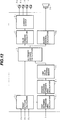
- Fig. 11 is a diagram showing a work area limitation control system for a construction machine according to a second embodiment of the present invention, along with a hydraulic drive system thereof.
- Fig. 12 is a functional block diagram showing control functions of a control unit according to the second embodiment.
- Fig. 13 is a view showing first and second entrance forbidden areas and set distances for use in the work area limitation control system of the second embodiment.
- Fig. 14 is a flowchart showing processing procedures of the control unit.
- a first embodiment of the present invention which is applied to a hydraulic excavator, will be described below with reference to Figs. 1 to 10. Note that the first embodiment is adapted for overhead area limitation control.
- a hydraulic excavator to which the present invention is applied includes a hydraulic drive system comprising a hydraulic pump 2, a plurality of hydraulic actuators driven by a hydraulic fluid supplied from the hydraulic pump 2, including a boom cylinder 3a, an arm cylinder 3b, a bucket cylinder 3c, a swing motor 3d, and left and right track motors 3e, 3f, a plurality of control lever units 4a - 4f associated respectively with the hydraulic actuators 3a - 3f, a plurality of flow control valves 5a - 5f connected between the hydraulic pump 2 and the plurality of hydraulic actuators 3a - 3f and driven in accordance with operation signals input from the control lever units 4a - 4f for controlling flow rates of the hydraulic fluid supplied to the hydraulic actuators 3a - 3f, and a relief valve 6 made open when a pressure between the hydraulic pump 2 and the flow control valves 5a - 5f exceeds a preset value.
- the hydraulic excavator comprises, as shown in Fig. 2, a multi-articulated working device, i.e., a front device 1A, made up of a boom 1a, an arm 1b and a bucket 1c which are each pivotable in the vertical direction, and a vehicle (machine) body 1B consisted of an upper structure 1d and an undercarriage 1e.
- the boom 1a of the front device 1A is supported at its base end to a front portion of the upper structure 1d.
- the boom 1a, the arm 1b, the bucket 1c, the upper structure 1d and the undercarriage 1e are driven respectively by the boom cylinder 3a, the arm cylinder 3b, the bucket cylinder 3c, the swing motor 3d, and the left and right track motors 3e, 3f.
- the control lever units 4a - 4f are of hydraulic pilot type and produce respective pilot pressures to drive the associated flow control valves 5a - 5f. As shown in Fig. 3, the control lever units 4a - 4f each comprise a control lever 40 operated by an operator, and a pair of pressure reducing valves 41, 42 producing a pilot pressure depending on the amount and the direction by and in which the control lever 40 is operated.
- the pairs of pressure reducing valves 41, 42 have primary ports connected to a pilot pump 43 and secondary ports connected to hydraulic driving sectors 50a, 50b; 51a, 51b; 52a, 52b; 53a, 53b; 54a, 54b; 55a, 55b of the associated flow control valves through respective pilot lines 44a, 44b; 45a, 45b; 46a, 46b; 47a, 47b; 48a, 48b; 49a, 49b.
- a work area limitation control system of this embodiment is equipped on the hydraulic excavator constructed as described above.
- the limitation control system comprises a setting device 7 for instructing setting of an area where the front device 1A should not enter (hereinafter referred to as a first entrance forbidden area) in advance depending on the type of work to be performed, angle sensors 8a, 8b, 8c disposed at respective pivot points, i.e., articulated joints, of the boom 1a, the arm 1b and the bucket 1c for detecting respective rotational angles as status variables in relation to the position and attitude of the front device 1A, a control unit 9 for receiving a setting signal from the setting device 7 and detection signals from the angle sensors 8a, 8b, 8c and then outputting electric signals as command signals for limiting a work area of the front device 1A, and proportional solenoid valves 10a, 10b, 11a, 11b driven by the electric signals output from the control unit 9.
- the proportional solenoid valves 10a, 10b, 11a, 11b are disposed respectively in the pilot lines 44a, 44b, 45a, 45b and reduce the pilot pressures produced by the associated control lever units 4a, 4b in accordance with the respective electric signals input thereto, followed by outputting the reduced pilot pressures.
- the setting device 7 is to output, to the control unit 9, a setting signal for instructing setting of an entrance forbidden area through input means, such as a switch, provided on a control panel or a grip.
- the control panel may also include thereon other aid means such as a display.
- a setting signal may be applied to the control unit 9 in any other suitable manner such as using IC cards, bar codes, lasers or wireless communication.
- Control functions of the control unit 9 are shown in Fig. 4.
- the control unit 9 has functions executed by a first entrance forbidden area calculating portion 9a, a second entrance forbidden area calculating portion 9b, a limit value storing memory portion 9c, a front attitude calculating portion 9d, a slowdown control calculating portion 9e, a maximum cylinder speed calculating portion 9f, a maximum pilot pressure calculating portion 9g, a valve command calculating portion 9h, and a current output portion 9i.
- the first entrance forbidden area calculating portion 9a sets and calculates, in response to the instruction from the setting device 7, the first entrance forbidden area where the front device 1A should not enter.
- This function will be described with reference to Fig. 5.
- a plurality of monitoring points P1 - P5 are set on the front device 1A at predetermined positions beforehand.
- the operator starts operation to move up the front device 1A to a height at which an overhead limit is to be set.
- respective heights P1z - P5z of the monitoring points P1 - P5 are calculated and maximum one of the calculated values is set as a boundary value (P cz1 ) of the first entrance forbidden area.
- the monitoring point P2 set at a rear end of the arm 1b is at the highest level and, therefore, the height P2z of the monitoring point P2 is set as a boundary value (P cz1 ) of the first entrance forbidden area.
- the values of P1z to P5z are calculated in the front attitude calculating portion 9d.
- the second entrance forbidden area calculating portion 9b calculates a boundary value (P cz2 ) of a second entrance forbidden area from the boundary value (P cz1 ) of the first entrance forbidden area calculated by the first entrance forbidden area calculating portion 9a.
- the monitoring point P1 is set at the pivot point between the boom 1a and the arm 1b.
- the limit value storing memory portion 9c stores the boundary values P cz1 , P cz2 calculated by the first and second entrance forbidden area calculating portions 9a, 9b.
- the front attitude calculating portion 9d calculates a position and attitude of the front device 1A based on the rotational angles of the boom, the arm and the bucket detected by the angle sensors 8a - 8c and other such data as respective dimensions LA1, LA2, LA3, LA4, LB1, LV1, LV2, LV3 of the front device 1A and the vehicle body 1B, shown in Fig. 5, which are stored in a storage of the control unit 9 beforehand.
- the position and attitude of the front device 1A is determined as coordinate values of an XZ-coordinate system with the pivot point of the boom 1a, for example, being at the origin.
- the XZ-coordinate system is a rectangular coordinate system fixed on the vehicle body 1B and lying in a vertical plane.
- the front attitude calculating portion 9d continues to calculate respective positions of the monitoring points P1 - P5.
- This embodiment uses the two monitoring points P1, P5 in calculation for overhead limit control.
- the monitoring point P1 is set at the pivot point between the boom 1a and the arm 1b, as mentioned above, and the monitoring point P5 is set at the highest point on a circle having a radius LV1 (distance from a bucket pin to a bucket tip end) about the pivot center (bucket pin) of the bucket 1c.
- the Z-coordinate values of the monitoring points P1 - P5 calculated by the front attitude calculating portion 9d are determined based on rotational angles ⁇ , ⁇ , ⁇ and the respective dimensions shown in Fig. 5, which are stored in the storage, by using formulae below;
- P 1z - LB1 sin ⁇
- P 2z LA2 sin( ⁇ + ⁇ ) + LA3 cos( ⁇ + ⁇ ) - LB1 sin ⁇
- P 3z - LV1 sin( ⁇ + ⁇ + ⁇ ) - LA1 sin( ⁇ + ⁇ ) - LB1 sin ⁇
- P 4z - LV2 sin( ⁇ + ⁇ + ⁇ ) + LA3 cos( ⁇ + ⁇ + ⁇ ) - LA1 sin( ⁇ + ⁇ ) - LB1 sin ⁇
- P 5z - LA1 sin( ⁇ + ⁇ ) - LB1 sin ⁇ + LV1 where ⁇ , ⁇ , ⁇ are positive in the clockwise direction as indicated by arrow in Fig. 5.
- the slowdown control calculating portion 9e calculates slowdown command signals K BU , K BD for the boom cylinder 3a in the extending and contracting directions thereof and K AC , K AD for the arm cylinder 3b in the extending and contracting directions thereof based on the Z-coordinate values P1z, P5z of the monitoring points P1, P5 calculated by the front attitude calculating portion 9d, the boundary values P cz1 , P cz2 of the first and second entrance forbidden areas stored in the limit value storing memory portion 9c, a distance (hereinafter referred to as a slowdown distance) Lj indicating the extent of a slowdown area, and a slowdown function (described later), the slowdown distance Lj and the slowdown function being both stored in the storage of the control unit 9.
- a slowdown distance Lj indicating the extent of a slowdown area
- a slowdown function described later
- the calculating portion 9e calculates a distance Lj1 between the monitoring point P1 and the second entrance forbidden area, and a distance Lj5 between the monitoring point P5 and the first entrance forbidden area. Then, the slowdown command signals are determined as follows.
- Fig. 7(a) represents the case of the above (2)
- Fig. 7(b) represents the case of the above (3)
- Fig. 7(c) represents the case of the above (4), respectively.
- the slowdown command signal K BU is given by a smaller value of the slowdown command signals calculated in the above two cases (2) and (3), and the slowdown command signal K AD is given by the same value as calculated in the above case (3).
- the slowdown command signal K BU is kept at 0 so that the boom 3a will not move up above a level of the boundary P cz2 of the second entrance forbidden area, whereas only the operation of the arm cylinder 3b in the contracting direction (arm dumping operation) is slowed down.
- the maximum cylinder speed calculating portion 9f calculates maximum cylinder speeds V BU max c , V BD max c of the boom extending and contracting operations during slowdown and maximum cylinder speeds V AC max c , V AD max c of the arm extending and contracting operations during slowdown based on maximum cylinder speeds V BU max, V BD max in the boom extending and contracting directions and maximum cylinder speeds V AC max, V AD max in the arm extending and contracting directions which are stored in the control unit 9 beforehand, as well as the above slowdown command signals K BU , K BD , K AC , K AD .
- V BU max c K BU x V BU max
- V BD max c K BD x V BD max
- V AC max c K AC x V AC max
- V AD max c K AD x V AD max
- the maximum pilot pressure calculating portion 9g calculates maximum load pressures P BU max c , P BD max c for the boom extending and contracting operations during slowdown and maximum load pressures P AC max c , P AD max c for the arm extending and contracting operations during slowdown based on V BU max c , V BD max c , V AC max c , V AD max c calculated by the maximum cylinder speed calculating portion 9f and tables indicating the relationships between pilot pressures and cylinder speeds, as shown in Fig. 8, which are stored in the control unit 9 beforehand.
- the valve command calculating portion 9h calculates electric signals i BU , i BD , i AC , i AD for the electric pressure reducing valves 10a, 10b, 11a, 11b for restricting speeds of the boom extending and contracting operations and the arm extending and contracting operations based on P BU max c , P BD max c , P AC max c , P AD max c calculated by the maximum pilot pressure calculating portion 9g and tables indicating the relationship between a pilot pressure and a current value, as shown in Fig. 9, which is stored in the control unit 9 beforehand.
- the current output portion 9i outputs current values corresponding to i BU , i BD , i AC , i AD to the electric pressure reducing valves 10a, 10b, 11a, 11b, respectively.
- steps 400, 410 correspond to the front attitude calculating portion 9d
- steps 200, 500 - 550 correspond to the slowdown control calculating portion 9e
- step 600 corresponds to the maximum cylinder speed calculating portion 9f
- steps 700, 710 correspond to the maximum pilot pressure calculating portion 9g
- step 800 corresponds to the valve command calculating portion 9h
- steps 900, 910 correspond to the current output portion 9i.
- steps 300 - 320 represent initialization for the sake of safety.
- the control lever units 4a - 4f constitute a plurality of operating means for instructing the operation of a plurality of front members
- the monitoring point P1 corresponds to a first monitoring point set on the second front member
- the second entrance forbidden area calculating portion 9b and the limit value storing memory portion 9c in the control unit 9 cooperatively constitute entrance forbidden area setting means for setting the second entrance forbidden area positioned closer to the front device 1A than the first entrance forbidden area.
- the angle sensors 8a, 8b, 8c, the proportional solenoid valves 10a, 10b, 11a, 11b, the front attitude calculating portion 9d, the slowdown control calculating portion 9e, the maximum cylinder speed calculating portion 9f, the maximum pilot pressure calculating portion 9g, the valve command calculating portion 9h, and the current output portion 9i, these portions being in the control unit 9, cooperatively constitute first operation signal modifying means for modifying the operation signals input from the operating means for the first and second front members such that immediately before the first monitoring point set on the second front member enters the second entrance forbidden area, the first front member is stopped, but the second front member is kept allowed to move. Further, as seen from the above description, the first operation signal modifying means also modifies the operation signal input from the operating means for the first front member such that the first front member is slowed down as the first monitoring point comes closer to the second entrance forbidden area.
- the monitoring point P5 corresponds to a second monitoring point set on the front device 1A, and the angle sensors 8a, 8b, 8c, the proportional solenoid valves 10a, 10b, 11a, 11b, and the front attitude calculating portion 9d, the slowdown control calculating portion 9e, the maximum cylinder speed calculating portion 9f, the maximum pilot pressure calculating portion 9g, the valve command calculating portion 9h, and the current output portion 9i, these portions being in the control unit 9, cooperatively constitute second operation signal modifying means for modifying the operation signals input from the operating means for the first and second front members such that immediately before the second monitoring point set on the front device 1A enters the first entrance forbidden area, the first and second front members are both stopped. Further, as seen from the above description, the second operation signal modifying means also modifies the operation signals input from the operating means for the first and second front members such that the first and second front members are both slowed down as the second monitoring point comes closer to the first entrance forbidden area.
- the distance LA4 (i.e., the distance from the monitoring point P1 to the monitoring point P2 set at the rear end of the arm 1b), which is subtracted from the boundary P cz1 of the first entrance forbidden area when the boundary P cz2 of the second entrance forbidden area is calculated by the second entrance forbidden area calculating portion 9b, is a distance enough to prevent any part of the second front member from entering the first entrance forbidden area when the second front member is moved in a condition where the first monitoring point is positioned on the boundary of the second entrance forbidden area.
- the aforesaid entrance forbidden area setting means sets the second entrance forbidden area at a level spaced from the first entrance forbidden area by that distance.
- the front attitude calculating portion 9d calculates positions of the monitoring points P1 - P5, and the slowdown control calculating portion 9e calculates a distance Lj1 between the monitoring point p1 and the boundary P cz2 of the second entrance forbidden area and a distance Lj5 between the monitoring point p5 and the boundary P cz1 of the first entrance forbidden area based on the Z-coordinate values P1z, P5z of the monitoring points P1, P5 calculated by the front attitude calculating portion 9d and the boundary values P cz1 , P cz2 of the first and second entrance forbidden areas stored in the limit value storing memory portion 9c, and then compares the calculated distances Lj1, Lj5 with the slowdown distance Lj to determine whether or not the monitoring points P1, P5 are in the respective slowdown areas.
- the slowdown command signals K BD , K AC and K AD remain kept at 1, allowing the arm 1b to be moved freely.
- the operation of the boom cylinder 3a in the extending direction i.e., the boom-up operation
- the operation of the arm cylinder 3b in the contracting direction i.e., the arm dumping operation
- the operation of the boom cylinder 3a in the extending direction i.e., the boom-up operation
- the operation of the arm cylinder 3b in the contracting direction i.e., the arm dumping operation
- the slowdown command signal K BU since the slowdown command signal K BU is provided by smaller one of the slowdown command signals calculated in the above cases (2) and (3), the slowdown command signal K BU becomes 0 and the boom 3a is prevented from moving up beyond a level of the boundary P cz2 of the second entrance forbidden area after the monitoring point P1 has reached the boundary P cz2 of the second entrance forbidden area.
- the boom 1a is slowed down, but the arm 1b remains freely movable unless the monitoring point P5 enters the slowdown area. This also contributes to suppressing a deterioration of maneuverability.
- the second entrance forbidden area is set to position closer to the front device than the first entrance forbidden area by the distance LA4
- the rear end of the arm 1b i.e., any part of the front device 1A
- the front device 1A is prevented from contacting an obstacle.
- the boom 1a and the arm 1b are gradually slowed down and then smoothly stopped immediately before the second entrance forbidden area and the first entrance forbidden area, respectively.
- the front device 1A is completely stopped there and will not enter the first entrance forbidden area.
- FIG. 11 to 14 A second embodiment of the present invention will be described with reference to Figs. 11 to 14. This second embodiment is also adapted for overhead area limitation control.
- Figs. 11 to 14 equivalent members and components to those in the above-referred drawings are denoted by the same reference numerals.
- a work area limitation control system of this embodiment includes a buzzer 56 in addition to the arrangement of the first embodiment shown in Fig. 1.
- the buzzer 56 is turned on to produce sounds under control of a control unit 9A when a monitoring point set on the front device 1A comes close to a preset entrance forbidden area, thereby informing the operator of the presence of danger.
- the control unit 9A has control functions as shown in Fig. 12. More specifically, the control unit 9A has functions executed by a first entrance forbidden area calculating portion 9a, a second entrance forbidden area calculating portion 9b, a limit value storing memory portion 9c, a front attitude calculating portion 9d, an allowance distance calculating portion 9j, a valve command calculating portion 9h, a current output portion 9i, and a buzzer control calculating portion 9m.
- the functions of the first entrance forbidden area calculating portion 9a, the second entrance forbidden area calculating portion 9b, the limit value storing memory portion 9c, the front attitude calculating portion 9d, the current output portion 9i are the same as described above in connection with the first embodiment.
- the allowance distance calculating portion 9j calculates a distance Lj1 between the monitoring point P1 and the second entrance forbidden area and a distance Lj5 between the monitoring point P5 and the first entrance forbidden area based on the Z-coordinate values P1z, P5z of the monitoring points P1, P5 calculated by the front attitude calculating portion 9d and the boundary values P cz1 , P cz2 of the first and second entrance forbidden areas stored in the limit value storing memory portion 9c.
- the valve command calculating portion 9h compares the distances Lj1, Lj5 calculated by the allowance distance calculating portion 9j with preset distances Lm1, Lm5 and, based on the compared results, calculates electric signals i BU , i BD , i AC , i AD to be output to the electric pressure reducing valves 10a, 10b, 11a, 11b.
- the distances Lm1, Lm5 are allowance distances with which the front device can be stopped without entering the first and second entrance forbidden areas in spite of a delay in the control system and so on, when the operator returns the control lever units to their neutral positions.
- the electric signals i BU , i BD , i AC , i AD are calculated as follows.
- the buzzer control calculating portion 9m compares the distances Lj1, Lj5 calculated by the allowance distance calculating portion 9j with preset distances Lb1, Lb5 and, based on the compared results, calculates an electric signal to be output to the buzzer 56.
- the distances Lb1, Lb5 are alarm distances used for alarming that the monitoring points P1, P5 have come close to the first and second entrance forbidden areas, respectively, and are set to meet Lb1 > Lm1 and Lb5 > Lm5.
- the electric signal is calculated as follows.
- steps 400, 410 correspond to the front attitude calculating portion 9d
- steps 200, 1000 correspond to the allowance distance calculating portion 9j
- step 1100, 1110 correspond to the buzzer control calculating portion 9m
- steps 1200, 1260 correspond to the valve command calculating portion 9h
- steps 900, 910 correspond to the current output portion 9i.
- the boom-up operation is stopped when the monitoring point P1 is at the distance Lm1 from the second entrance forbidden area, but arm stop control is not effected unless the monitoring point P5 reaches the distance Lm5 from the first entrance forbidden area.
- arm stop control is not effected unless the monitoring point P5 reaches the distance Lm5 from the first entrance forbidden area.
- the boom operating speed becomes 0 immediately before the monitoring point P1 enters the second entrance forbidden area. But, since the second entrance forbidden area is set at a level lower than the first entrance forbidden area by LA4, the rear end of the arm will not enter the first entrance forbidden area even when the arm is moved after the boom has so stopped.
- the boom and the arm are both controlled to stop, and the operating speeds of both the boom and the arm become 0 immediately before the monitoring point P5 enters the first entrance forbidden area. Therefore, the front device can be stopped without entering the first entrance forbidden area.
- the buzzer 56 is turned on to produce intermittent sounds, thereby informing the operator of that the monitoring point P1 or P5 will soon reach the entrance forbidden area. Accordingly, the operator can slow down the actuator by relieving the manipulation grip of the control lever, so that a shock produced upon the actuator being stopped may be abated.
- the work area limitation control system of the present invention is not limited to the embodiments stated above, but can be modified in various ways.
- the angle sensors for detecting the rotational angles are employed as means for detecting the status variables relating to the position and attitude of the front device 1A
- cylinder strokes may be detected instead.
- the foregoing embodiments have been described in connection with the case of performing the area limitation control over the head, the present invention is also similarly applicable to the case of setting an entrance forbidden area defined by a vertical or inclined boundary in the front of the vehicle body. Likewise, an entrance forbidden area may be set at a low level.
- first front member is a boom and the second front member is an arm
- similar advantages can also be achieved with the present invention applied to the case where the first and second front members are an arm and a bucket.
- the present invention is applied to a construction machine which is an ordinary hydraulic excavator with a front device having a mono-boom.
- the present invention is also similarly applicable to a hydraulic excavator with a front device having a two-piece boom or a hydraulic excavator with a front device having an offset.
- similar advantages can also be achieved with the present invention applied to two booms of the two-piece boom or one boom of the two-piece boom and an arm in the former case and a boom and an offset or a boom and an arm in the latter case.
- the present invention is applied to a hydraulic drive system in which flow control valves are driven by control lever units of hydraulic pilot type as described, similar advantages can also be achieved with the present invention applied to a hydraulic drive system using electric control lever units.
Landscapes
- Engineering & Computer Science (AREA)
- Mining & Mineral Resources (AREA)
- Civil Engineering (AREA)
- General Engineering & Computer Science (AREA)
- Structural Engineering (AREA)
- Operation Control Of Excavators (AREA)
Abstract
Description
- The present invention relates to a work area limitation control system for a construction machine having a multi-articulated front device, and more particularly to a work area limitation control system for a hydraulic excavator having a front device made up of multiple front members such as an arm, a boom and a bucket.
- In a hydraulic excavator, a multi-articulated working device (front device) is constructed by attaching a boom to a front portion of an upper structure and connecting an arm and a bucket to a tip end of the boom tandem in the order named. Such work as digging and loading is carried out by controlling flexion movement of the working device.
- Meanwhile, in some job sites of hydraulic excavators, there is an obstacle above or in front of the excavator. An overhead obstacle is, e.g., a mid-air electric wire in outdoor work and the ceiling of a structure in indoor work. When the job site is, e.g., a residential area partitioned into narrow plots, a wall of a private house or the like often exists in front of the excavator, thus posing an obstacle in the front. During work, an operator must pay close attention so that part of a working device, e.g., a bucket prong, will not contact or catch such an obstacle, and this imposes a great burden on the operator.
- To cope with the above problem, JP-A-3-208923 discloses an invention as follows. In advance, an entrance forbidden area is set at an upper level and an actuator slowdown area is set at a level lower than the entrance forbidden area. When any one of tip end positions of front members making up a working device which is at the highest level enters the slowdown area, the operating speed of actuators is reduced to slow down the working device, and further when it reaches the entrance forbidden area, the operation of the actuators is ceased to stop the working device. Any part of the working device is thereby prevented from contacting an overhead obstacle.
- Also, JP-A-3-217523 discloses an invention that, to prevent a working device from interfering a cab, an entrance forbidden area is set in advance and, when a tip end of the working device reaches the entrance forbidden area, the operation of actuators is ceased to stop the working device.
- However, the foregoing prior art has problems below.
- An operator engaged in field work does not like that the operation of all actuators is suddenly stopped or the operating speed thereof is abruptly reduced during the work. The reason is that a sudden stop of the operation or an abrupt reduction in the operating speed of all actuators would lower maneuverability and reduce working efficiency. When the foregoing prior art is practiced in work requiring the working device to be moved into the vicinity of the entrance forbidden area, the operation of all actuators is suddenly stopped when the working device reaches the entrance forbidden area. Therefore, each time reaching the entrance forbidden area, the working device is completely stopped during the work, which results in a remarkable reduction in maneuverability and working efficiency. Further, in the case of the slowdown area being set, the operating speed of actuators is reduced in the vicinity of the entrance forbidden area, which also results in a reduction in maneuverability and working efficiency.
- An object of the present invention is to provide a work area limitation control system for a construction machine which can prevent a contact between a front device and an obstacle without reducing maneuverability to the extent possible.
- To achieve the above object, the present invention is constructed as follows.
- (1) Disclosed as the present invention is a work area limitation control system for a construction machine, the control system being equipped on a construction machine comprising a machine body, a multi-articulated front device made up of a plurality of front members including first and second front members connected to the machine body, a plurality of hydraulic actuators for driving the plurality of front members, a plurality of operating means for instructing operations of the plurality of front members, a plurality of flow control valves driven in accordance with operation signals input from the plurality of operating means for controlling flow rates of a hydraulic fluid supplied to the plurality of hydraulic actuators, the control system operating to cease supply of the hydraulic fluid to the hydraulic actuators to stop the front device when the front device reaches a preset first entrance forbidden area, wherein the control system comprises entrance forbidden area setting means for setting a second entrance forbidden area positioned closer to the front device than the first entrance forbidden area, and first operation signal modifying means for modifying the operation signals input from the operating means for the first and second front members such that immediately before a first monitoring point set on the second front member enters the second entrance forbidden area, the first front member is stopped, but the second front member is kept allowed to move.
With the feature set forth above, the first operation signal modifying means is provided to modify the operation signals input from the operating means such that when the first monitoring point set on the second front member is going to enter the second entrance forbidden area, the first front member is stopped immediately before the entrance, but the second front member is kept allowed to move. Therefore, when the first monitoring point reaches the boundary of the second entrance forbidden area, the first front member is stopped, but the second front member is kept freely movable. As a result, a deterioration of maneuverability is suppressed. Further, because of the second entrance forbidden area being set to position closer to the front device than the first entrance forbidden area, by properly setting a distance between the boundaries of both the entrance forbidden areas, any part of the front device is avoided from entering the first entrance forbidden area even when the second front member is moved after the first front member has stopped and, therefore, a contact between the front device and an obstacle is prevented. - (2) In the above (1), preferably, the first operation signal modifying means modifies the operation signal input from the operating means for the first front member such that when the first monitoring point comes close to the second entrance forbidden area, the first front member is slowed down.
By so slowing down the first front member by the first operation signal modifying means, the first front member is smoothly stopped immediately before entering the second entrance forbidden area. It is therefore possible to abate an overshooting of the first front member and a shock produced upon stoppage thereof. Also, while the first front member is brought under the slowdown control, the second front member remains freely movable unless it is per se brought under the slowdown control. As a result, a deterioration of maneuverability is suppressed to the least. - (3) In the above (1), preferably, the control system further comprises second operation signal modifying means for modifying the operation signals input from the operating means for the first and second front members such that immediately before a second monitoring point set on the front device enters the first entrance forbidden area, the first and second front members are both stopped.
By so further providing the second operation signal modifying means and stopping both the first and second front members immediately before the second monitoring point enters the first entrance forbidden area, the front device is avoided from entering the first entrance forbidden area. - (4) In the above (3), preferably, the second operation signal modifying means modifies the operation signals input from the operating means for the first and second front members such that when the second monitoring point comes close to the first entrance forbidden area, the first and second front members are both slowed down.
By so slowing down the first and second front members by the second operation signal modifying means, the first and second front member are smoothly stopped immediately before entering the second and first entrance forbidden areas, respectively. It is therefore possible to abate overshootings of the first and second front members and shocks produced upon stoppage thereof. - (5) In the above (1), preferably, the first and second front members are adjacent front members articulated with each other such that the second front member is pivotable relative to the first front member.
- (6) In the above (1), by way of example, the first and second front members are a boom and an arm of a hydraulic excavator.
- (7) In the above (1), preferably, the entrance forbidden area setting means sets the second entrance forbidden area to be spaced from the first entrance forbidden area by a distance enough to prevent any part of the second front member from entering the first entrance forbidden area when the second front member is moved in a condition where the first monitoring point is positioned on a boundary of the second entrance forbidden area.
By so setting the second entrance forbidden area, any part of the front device is avoided from entering the first entrance forbidden area even when the second front member is moved in such a condition. - (8) In the above (1), by way of example, the plurality of operating means are of hydraulic pilot type outputting pilot pressures as the operation signals, and the first operation signal modifying means includes pilot pressure modifying means for reducing the pilot pressure output from the operating means for the first front member down to a reservoir pressure immediately before the first monitoring point enters the second entrance forbidden area.
- (9) Also in the above (2), by way of example, the plurality of operating means are of hydraulic pilot type outputting pilot pressures as the operation signals, and the second operation signal modifying means includes pilot pressure modifying means for reducing the pilot pressures output from the operating means for the first and second front members down to a reservoir pressure immediately before the second monitoring point enters the first entrance forbidden area.
- (10) In the above (8) and (9), preferably, the pilot pressure modifying means includes electric pressure reducing valves disposed in pilot lines for transmitting the pilot pressures output from the operating means for the first and second front members to the associated flow control valves.
- Fig. 1 is a diagram showing a work area limitation control system for a construction machine according to a first embodiment of the present invention, along with a hydraulic drive system thereof.
- Fig. 2 is a perspective view showing an appearance of a hydraulic excavator to which the first embodiment is applied.
- Fig. 3 is a diagram showing details of a control lever unit of hydraulic pilot type.
- Fig. 4 is a functional block diagram showing control functions of a control unit according to the first embodiment.
- Fig. 5 is a view for explaining a method of setting a coordinate system and an area for use in the work area limitation control system of the first embodiment.
- Fig. 6 is a view showing first and second entrance forbidden areas and corresponding slowdown areas for use in the work area limitation control system of the first embodiment.
- Fig. 7 is a graph showing the relationship between a distance from a monitoring point to the entrance forbidden area and a slowdown command signal in a slowdown control calculating portion.
- Fig. 8 is a graph showing the relationship between a pilot pressure and a cylinder speed in a maximum pilot pressure calculating portion.
- Fig. 9 is a graph showing the relationship between a pilot pressure and a current value output to an electric pressure reducing valve in a valve command calculating portion.
- Fig. 10 is a flowchart showing processing procedures of the control unit.
- Fig. 11 is a diagram showing a work area limitation control system for a construction machine according to a second embodiment of the present invention, along with a hydraulic drive system thereof.
- Fig. 12 is a functional block diagram showing control functions of a control unit according to the second embodiment.
- Fig. 13 is a view showing first and second entrance forbidden areas and set distances for use in the work area limitation control system of the second embodiment.
- Fig. 14 is a flowchart showing processing procedures of the control unit.
- A first embodiment of the present invention, which is applied to a hydraulic excavator, will be described below with reference to Figs. 1 to 10. Note that the first embodiment is adapted for overhead area limitation control.
- In Fig. 1, a hydraulic excavator to which the present invention is applied includes a hydraulic drive system comprising a
hydraulic pump 2, a plurality of hydraulic actuators driven by a hydraulic fluid supplied from thehydraulic pump 2, including aboom cylinder 3a, anarm cylinder 3b, a bucket cylinder 3c, a swing motor 3d, and left andright track motors 3e, 3f, a plurality of control lever units 4a - 4f associated respectively with thehydraulic actuators 3a - 3f, a plurality of flow control valves 5a - 5f connected between thehydraulic pump 2 and the plurality ofhydraulic actuators 3a - 3f and driven in accordance with operation signals input from the control lever units 4a - 4f for controlling flow rates of the hydraulic fluid supplied to thehydraulic actuators 3a - 3f, and arelief valve 6 made open when a pressure between thehydraulic pump 2 and the flow control valves 5a - 5f exceeds a preset value. - Also, the hydraulic excavator comprises, as shown in Fig. 2, a multi-articulated working device, i.e., a
front device 1A, made up of a boom 1a, anarm 1b and abucket 1c which are each pivotable in the vertical direction, and a vehicle (machine)body 1B consisted of anupper structure 1d and anundercarriage 1e. The boom 1a of thefront device 1A is supported at its base end to a front portion of theupper structure 1d. The boom 1a, thearm 1b, thebucket 1c, theupper structure 1d and theundercarriage 1e are driven respectively by theboom cylinder 3a, thearm cylinder 3b, the bucket cylinder 3c, the swing motor 3d, and the left andright track motors 3e, 3f. - The control lever units 4a - 4f are of hydraulic pilot type and produce respective pilot pressures to drive the associated flow control valves 5a - 5f. As shown in Fig. 3, the control lever units 4a - 4f each comprise a control lever 40 operated by an operator, and a pair of pressure reducing valves 41, 42 producing a pilot pressure depending on the amount and the direction by and in which the control lever 40 is operated. The pairs of pressure reducing valves 41, 42 have primary ports connected to a
pilot pump 43 and secondary ports connected tohydraulic driving sectors 50a, 50b; 51a, 51b; 52a, 52b; 53a, 53b; 54a, 54b; 55a, 55b of the associated flow control valves throughrespective pilot lines 44a, 44b; 45a, 45b; 46a, 46b; 47a, 47b; 48a, 48b; 49a, 49b. - A work area limitation control system of this embodiment is equipped on the hydraulic excavator constructed as described above. The limitation control system comprises a
setting device 7 for instructing setting of an area where thefront device 1A should not enter (hereinafter referred to as a first entrance forbidden area) in advance depending on the type of work to be performed,angle sensors arm 1b and thebucket 1c for detecting respective rotational angles as status variables in relation to the position and attitude of thefront device 1A, acontrol unit 9 for receiving a setting signal from thesetting device 7 and detection signals from theangle sensors front device 1A, andproportional solenoid valves 10a, 10b, 11a, 11b driven by the electric signals output from thecontrol unit 9. Theproportional solenoid valves 10a, 10b, 11a, 11b are disposed respectively in thepilot lines 44a, 44b, 45a, 45b and reduce the pilot pressures produced by the associated control lever units 4a, 4b in accordance with the respective electric signals input thereto, followed by outputting the reduced pilot pressures. - The
setting device 7 is to output, to thecontrol unit 9, a setting signal for instructing setting of an entrance forbidden area through input means, such as a switch, provided on a control panel or a grip. The control panel may also include thereon other aid means such as a display. Alternatively, a setting signal may be applied to thecontrol unit 9 in any other suitable manner such as using IC cards, bar codes, lasers or wireless communication. - Control functions of the
control unit 9 are shown in Fig. 4. Thecontrol unit 9 has functions executed by a first entrance forbidden area calculating portion 9a, a second entrance forbidden area calculating portion 9b, a limit value storing memory portion 9c, a frontattitude calculating portion 9d, a slowdowncontrol calculating portion 9e, a maximum cylinderspeed calculating portion 9f, a maximum pilotpressure calculating portion 9g, a valvecommand calculating portion 9h, and acurrent output portion 9i. - The first entrance forbidden area calculating portion 9a sets and calculates, in response to the instruction from the
setting device 7, the first entrance forbidden area where thefront device 1A should not enter. One example of this function will be described with reference to Fig. 5. - In Fig. 5, a plurality of monitoring points P1 - P5 are set on the
front device 1A at predetermined positions beforehand. The operator starts operation to move up thefront device 1A to a height at which an overhead limit is to be set. Under this condition, in response to the instruction from thesetting device 7, respective heights P1z - P5z of the monitoring points P1 - P5 are calculated and maximum one of the calculated values is set as a boundary value (Pcz1) of the first entrance forbidden area. In the illustrated example, the monitoring point P2 set at a rear end of thearm 1b is at the highest level and, therefore, the height P2z of the monitoring point P2 is set as a boundary value (Pcz1) of the first entrance forbidden area. Note that the values of P1z to P5z are calculated in the frontattitude calculating portion 9d. - The second entrance forbidden area calculating portion 9b calculates a boundary value (Pcz2) of a second entrance forbidden area from the boundary value (Pcz1) of the first entrance forbidden area calculated by the first entrance forbidden area calculating portion 9a. The calculation formula used here is below;

arm 1b. The monitoring point P1 is set at the pivot point between the boom 1a and thearm 1b. - The limit value storing memory portion 9c stores the boundary values Pcz1, Pcz2 calculated by the first and second entrance forbidden area calculating portions 9a, 9b.
- The front
attitude calculating portion 9d calculates a position and attitude of thefront device 1A based on the rotational angles of the boom, the arm and the bucket detected by theangle sensors 8a - 8c and other such data as respective dimensions LA1, LA2, LA3, LA4, LB1, LV1, LV2, LV3 of thefront device 1A and thevehicle body 1B, shown in Fig. 5, which are stored in a storage of thecontrol unit 9 beforehand. At this time, the position and attitude of thefront device 1A is determined as coordinate values of an XZ-coordinate system with the pivot point of the boom 1a, for example, being at the origin. The XZ-coordinate system is a rectangular coordinate system fixed on thevehicle body 1B and lying in a vertical plane. - In the setting process of the first entrance forbidden area by the calculating portion 9a, the front
attitude calculating portion 9d calculates respective values of the monitoring points P1 - P5 as Z-coordinate values in the XZ-coordinate system, and sets maximum one of the calculated values as the boundary value (Z-coordinate value = Pcz1) of the first entrance forbidden area. - Further, during the operation of the hydraulic excavator, the front
attitude calculating portion 9d continues to calculate respective positions of the monitoring points P1 - P5. This embodiment uses the two monitoring points P1, P5 in calculation for overhead limit control. The monitoring point P1 is set at the pivot point between the boom 1a and thearm 1b, as mentioned above, and the monitoring point P5 is set at the highest point on a circle having a radius LV1 (distance from a bucket pin to a bucket tip end) about the pivot center (bucket pin) of thebucket 1c. - The Z-coordinate values of the monitoring points P1 - P5 calculated by the front
attitude calculating portion 9d are determined based on rotational angles α, β, γ and the respective dimensions shown in Fig. 5, which are stored in the storage, by using formulae below;
- The slowdown
control calculating portion 9e calculates slowdown command signals KBU, KBD for theboom cylinder 3a in the extending and contracting directions thereof and KAC, KAD for thearm cylinder 3b in the extending and contracting directions thereof based on the Z-coordinate values P1z, P5z of the monitoring points P1, P5 calculated by the frontattitude calculating portion 9d, the boundary values Pcz1, Pcz2 of the first and second entrance forbidden areas stored in the limit value storing memory portion 9c, a distance (hereinafter referred to as a slowdown distance) Lj indicating the extent of a slowdown area, and a slowdown function (described later),
the slowdown distance Lj and the slowdown function being both stored in the storage of thecontrol unit 9. This calculation process will be described below in more detail with reference to Fig. 6. - First, the calculating
portion 9e calculates a distance Lj1 between the monitoring point P1 and the second entrance forbidden area, and a distance Lj5 between the monitoring point P5 and the first entrance forbidden area. Then, the slowdown command signals are determined as follows. - (1) If the distances Lj1, Lj5 are both not less than the slowdown distance Lj (i.e., Lj1 ≥ Lj and Lj5 ≥ Lj), the slowdown command signals KBU, KBD, KAC, KAD are all set to one (1). Thus:

- (2) If Lj1 < Lj and Lj5 ≥ Lj, KBU, KBD, KAC and KAD are determined with the following formulae:

- (3) If Lj1 ≥ Lj and Lj5 < Lj, KBU, KBD, KAC and KAD are determined with the following formulae:

- (4) If Lj1 < Lj and Lj5 < Lj, KBU, KBD, KAC and KAD are determined with the following formulae:

- The above formulae are represented in the graphic form in Fig. 7. In graphs of Fig. 7, Fig. 7(a) represents the case of the above (2), Fig. 7(b) represents the case of the above (3), and Fig. 7(c) represents the case of the above (4), respectively. In the case of the above (2), as shown in Fig. 7(a), the slowdown command signal KBU is linearly reduced from 1 as the distance Lj1 reduces within the extent of the slowdown distance Lj, and then becomes nil (0) at the distance

boom cylinder 3a in the extending direction (boom-up operation) is slowed down, and when the monitoring point P1 reaches the boundary Pcz2 of the second entrance forbidden area, the boom-up operation is stopped. The other slowdown command signals KBD, KAC, KAD remain 1 so that thearm 1b is kept freely movable. - In the case of the above (3), as shown in Fig. 7(b), the slowdown command signals KBU, KAD are linearly reduced from 1 as the distance Lj5 reduces within the extent of the slowdown distance Lj, and then become 0 at the distance

boom cylinder 3a in the extending direction (boom-up operation) and the operation of thearm cylinder 3b in the contracting direction (arm dumping operation) are both slowed down, and when the monitoring point P5 reaches the boundary Pcz1 of the first entrance forbidden area, the boom-up operation and the arm dumping operation are both stopped. - In the case of the above (4), as shown in Fig. 7(c), the slowdown command signal KBU is given by a smaller value of the slowdown command signals calculated in the above two cases (2) and (3), and the slowdown command signal KAD is given by the same value as calculated in the above case (3). Stated otherwise, after the monitoring point P1 has reached the boundary Pcz2 of the second entrance forbidden area, the slowdown command signal KBU is kept at 0 so that the
boom 3a will not move up above a level of the boundary Pcz2 of the second entrance forbidden area, whereas only the operation of thearm cylinder 3b in the contracting direction (arm dumping operation) is slowed down. - The maximum cylinder
speed calculating portion 9f calculates maximum cylinder speeds VBUmaxc, VBDmaxc of the boom extending and contracting operations during slowdown and maximum cylinder speeds VACmaxc, VADmaxc of the arm extending and contracting operations during slowdown based on maximum cylinder speeds VBUmax, VBDmax in the boom extending and contracting directions and maximum cylinder speeds VACmax, VADmax in the arm extending and contracting directions which are stored in thecontrol unit 9 beforehand, as well as the above slowdown command signals KBU, KBD, KAC, KAD. The calculation formulae used here are below:
- The maximum pilot
pressure calculating portion 9g calculates maximum load pressures PBUmaxc, PBDmaxc for the boom extending and contracting operations during slowdown and maximum load pressures PACmaxc, PADmaxc for the arm extending and contracting operations during slowdown based on VBUmaxc, VBDmaxc, VACmaxc, VADmaxc calculated by the maximum cylinderspeed calculating portion 9f and tables indicating the relationships between pilot pressures and cylinder speeds, as shown in Fig. 8, which are stored in thecontrol unit 9 beforehand. - The valve
command calculating portion 9h calculates electric signals iBU, iBD, iAC, iAD for the electricpressure reducing valves 10a, 10b, 11a, 11b for restricting speeds of the boom extending and contracting operations and the arm extending and contracting operations based on PBUmaxc, PBDmaxc, PACmaxc, PADmaxc calculated by the maximum pilotpressure calculating portion 9g and tables indicating the relationship between a pilot pressure and a current value, as shown in Fig. 9, which is stored in thecontrol unit 9 beforehand. - The
current output portion 9i outputs current values corresponding to iBU, iBD, iAC, iAD to the electricpressure reducing valves 10a, 10b, 11a, 11b, respectively. - Here, the maximum pilot pressures PBUmaxc, PBDmaxc, PACmaxc, PADmaxc during slowdown calculated by the maximum pilot
pressure calculating portion 9g when the slowdown command signals calculated by the slowdowncontrol calculating portion 9e are KBU = 1, KBD = 1, KAC = 1 and KAD = 1, are set to maximum pilot pressures (rated pilot pump pressures) and the command electric values iBU, iBD, iAC, iAD calculated at this time are meant to fully open the electricpressure reducing valves 10a, 10b, 11a, 11b. Also, when KBU = 0, KBD = 0, KAC = 0 and KAD = 0 hold, the maximum pilot pressures PBUmaxc, PBDmaxc, PACmaxc, PADmaxc during slowdown are made 0 and the command electric values iBU, iBD, iAC, iAD calculated at this time are meant to fully close the electricpressure reducing valves 10a, 10b, 11a, 11b. - The flow of the foregoing control process is shown in a flowchart of Fig. 10.
- In Fig. 10,
steps attitude calculating portion 9d, steps 200, 500 - 550 correspond to the slowdowncontrol calculating portion 9e,step 600 corresponds to the maximum cylinderspeed calculating portion 9f, steps 700, 710 correspond to the maximum pilotpressure calculating portion 9g, step 800 corresponds to the valvecommand calculating portion 9h, and steps 900, 910 correspond to thecurrent output portion 9i. Furthermore, steps 300 - 320 represent initialization for the sake of safety. - In the above arrangement, supposing that the boom 1a is a first front member and the
arm 1b is a second front member, the control lever units 4a - 4f constitute a plurality of operating means for instructing the operation of a plurality of front members, the monitoring point P1 corresponds to a first monitoring point set on the second front member, and the second entrance forbidden area calculating portion 9b and the limit value storing memory portion 9c in thecontrol unit 9 cooperatively constitute entrance forbidden area setting means for setting the second entrance forbidden area positioned closer to thefront device 1A than the first entrance forbidden area. Also, theangle sensors proportional solenoid valves 10a, 10b, 11a, 11b, the frontattitude calculating portion 9d, the slowdowncontrol calculating portion 9e, the maximum cylinderspeed calculating portion 9f, the maximum pilotpressure calculating portion 9g, the valvecommand calculating portion 9h, and thecurrent output portion 9i, these portions being in thecontrol unit 9, cooperatively constitute first operation signal modifying means for modifying the operation signals input from the operating means for the first and second front members such that immediately before the first monitoring point set on the second front member enters the second entrance forbidden area, the first front member is stopped, but the second front member is kept allowed to move. Further, as seen from the above description, the first operation signal modifying means also modifies the operation signal input from the operating means for the first front member such that the first front member is slowed down as the first monitoring point comes closer to the second entrance forbidden area. - The monitoring point P5 corresponds to a second monitoring point set on the
front device 1A, and theangle sensors proportional solenoid valves 10a, 10b, 11a, 11b, and the frontattitude calculating portion 9d, the slowdowncontrol calculating portion 9e, the maximum cylinderspeed calculating portion 9f, the maximum pilotpressure calculating portion 9g, the valvecommand calculating portion 9h, and thecurrent output portion 9i, these portions being in thecontrol unit 9, cooperatively constitute second operation signal modifying means for modifying the operation signals input from the operating means for the first and second front members such that immediately before the second monitoring point set on thefront device 1A enters the first entrance forbidden area, the first and second front members are both stopped. Further, as seen from the above description, the second operation signal modifying means also modifies the operation signals input from the operating means for the first and second front members such that the first and second front members are both slowed down as the second monitoring point comes closer to the first entrance forbidden area. - In addition, the distance LA4 (i.e., the distance from the monitoring point P1 to the monitoring point P2 set at the rear end of the
arm 1b), which is subtracted from the boundary Pcz1 of the first entrance forbidden area when the boundary Pcz2 of the second entrance forbidden area is calculated by the second entrance forbidden area calculating portion 9b, is a distance enough to prevent any part of the second front member from entering the first entrance forbidden area when the second front member is moved in a condition where the first monitoring point is positioned on the boundary of the second entrance forbidden area. The aforesaid entrance forbidden area setting means sets the second entrance forbidden area at a level spaced from the first entrance forbidden area by that distance. - The operation of this embodiment thus constructed will now be described below.
- When the operator manipulates the control lever units 4a, 4b for the boom and the arm in the boom-up direction and in the arm dumping direction, respectively, with an intention of moving the
front device 1A upward, pilot pressures are produced in the pilot line 44a on the boom-up side and the pilot line 45b on the arm dumping side, whereupon the flow control valves 5a, 5b are driven to move the corresponding front members, i.e., the boom 1a and thearm 1b. Rotational angles of the boom 1a, thearm 1b and thebucket 1c articulated with each other are detected respectively by theangle sensors 8a - 8c and detection signals are input to the frontattitude calculating portion 9d. Based on these input signals, the frontattitude calculating portion 9d calculates positions of the monitoring points P1 - P5, and the slowdowncontrol calculating portion 9e calculates a distance Lj1 between the monitoring point p1 and the boundary Pcz2 of the second entrance forbidden area and a distance Lj5 between the monitoring point p5 and the boundary Pcz1 of the first entrance forbidden area based on the Z-coordinate values P1z, P5z of the monitoring points P1, P5 calculated by the frontattitude calculating portion 9d and the boundary values Pcz1, Pcz2 of the first and second entrance forbidden areas stored in the limit value storing memory portion 9c, and then compares the calculated distances Lj1, Lj5 with the slowdown distance Lj to determine whether or not the monitoring points P1, P5 are in the respective slowdown areas. - When the
front device 1A is not so raised and the monitoring points P1, P5 are far away from the first and second entrance forbidden areas, the slowdowncontrol calculating portion 9e determines, because of Lj1 ≥ Lj and Lj5 ≥ Lj, that the monitoring points P1, P5 are both not in the respective slowdown areas, and produces slowdown command signals of KBU = 1, KBD = 1, KAC = 1 and KAD = 1. Therefore, theproportional solenoid valves 10a, 10b, 11a, 11b are fully opened and the pilot pressures produced by the control lever units 4a, 4b are transmitted, as they are, to the flow control valve 5a for the boom and the flow control valve 5b for the arm, enabling thefront device 1A to be moved as manipulated by the operator. - When the
front device 1A is so raised that one of the monitoring points P1, P5, e.g., the monitoring point P1, reaches the slowdown area, the slowdowncontrol calculating portion 9e determines, because of Lj1 < Lj and Lj5 ≥ Lj, that the monitoring point P1 has entered the slowdown area, and calculates slowdown command signals of KBU < 1, KBD = 1, KAC = 1 and KAD = 1 from the formulae shown in the above case (2) (i.e., the relationship shown in Fig. 7(a)) depending on the distance Lj. Therefore, the operation of theboom cylinder 3a in the extending direction, i.e., the boom-up operation, is slowed down, while thearm 1b can be moved freely as manipulated by the operator. - When the
front device 1A is further raised and the monitoring point P1 reaches the second entrance forbidden area, the slowdowncontrol calculating portion 9e calculates the slowdown command signal KBU to be 0
because of
arm 1b to be moved freely. If the monitoring point P5 is in the slowdown area, the slowdown command signals KBU < 1, KBD = 1, KAC = 1 and KAD < 1 are calculated (as described below), whereby thearm 1b is slowed down, but not stopped. Since the second entrance forbidden area is spaced from the first entrance forbidden area by the distance LA4, any part of thearm 1b will not enter the first entrance forbidden area even when thearm 1b is moved after the boom-up operation has been stopped. - Returning to the foregoing case, when the other, i.e., P5, of the monitoring points P1, P5 reaches the slowdown area, the slowdown
control calculating portion 9e determines, because of Lj1 ≥ Lj and Lj5 < Lj, that the monitoring point P5 has entered the slowdown area, and calculates slowdown command signals of KBU < 1, KBD = 1, KAC = 1 and KAD < 1 from the formulae shown in the above case (3) (i.e., the relationship shown in Fig. 7(b)) depending on the distance Lj. Therefore, the operation of theboom cylinder 3a in the extending direction, i.e., the boom-up operation, and the operation of thearm cylinder 3b in the contracting direction, i.e., the arm dumping operation, are both slowed down. - Further, when both the monitoring points P1, P5 are in the slowdown area, the slowdown
control calculating portion 9e determines, because of Lj1 < Lj and Lj5 < Lj, that both the monitoring points P1, P5 have entered the slowdown area, and calculates slowdown command signals of KBU < 1, KBD = 1, KAC = 1 and KAD < 1 from the formulae shown in the above case (4) (i.e., the relationship shown in Fig. 7(c)) depending on the distance Lj. Therefore, the operation of theboom cylinder 3a in the extending direction, i.e., the boom-up operation, and the operation of thearm cylinder 3b in the contracting direction, i.e., the arm dumping operation, are both slowed down. In this case, since the slowdown command signal KBU is provided by smaller one of the slowdown command signals calculated in the above cases (2) and (3), the slowdown command signal KBU becomes 0 and theboom 3a is prevented from moving up beyond a level of the boundary Pcz2 of the second entrance forbidden area after the monitoring point P1 has reached the boundary Pcz2 of the second entrance forbidden area. - When only the
arm 1b is further raised and the monitoring point P5 reaches the first entrance forbidden area, the slowdowncontrol calculating portion 9e calculates the slowdown command signal KAD to be also 0 because of
arm cylinder 3b in the contracting direction, i.e., the arm dumping operation, is also stopped and hence thefront device 1A is completely stopped. - With this embodiment, as described above, when the monitoring point P1 reaches the boundary of the second entrance forbidden area, the boom 1a is stopped but the
arm 1b is not stopped. As a result, a deterioration of maneuverability can be suppressed to the least. - Also, when the monitoring point P1 enters the slowdown area, the boom 1a is slowed down, but the
arm 1b remains freely movable unless the monitoring point P5 enters the slowdown area. This also contributes to suppressing a deterioration of maneuverability. - Further, since the second entrance forbidden area is set to position closer to the front device than the first entrance forbidden area by the distance LA4, the rear end of the
arm 1b (i.e., any part of thefront device 1A) will not enter the first entrance forbidden area even when thearm 1b is moved after the boom 1a has stopped and, therefore, thefront device 1A is prevented from contacting an obstacle. - Moreover, when the monitoring points P1, P5 enter the slowdown areas, the boom 1a and the
arm 1b are gradually slowed down and then smoothly stopped immediately before the second entrance forbidden area and the first entrance forbidden area, respectively. As a result, it is possible to abate overshootings of the boom 1a and thearm 1b and shocks produced upon stoppage thereof. - Additionally, since the boom 1a and the
arm 1b are both stopped immediately before the monitoring point P5 enters the first entrance forbidden area, thefront device 1A is completely stopped there and will not enter the first entrance forbidden area. - A second embodiment of the present invention will be described with reference to Figs. 11 to 14. This second embodiment is also adapted for overhead area limitation control. In Figs. 11 to 14, equivalent members and components to those in the above-referred drawings are denoted by the same reference numerals.
- In Fig. 11, a work area limitation control system of this embodiment includes a buzzer 56 in addition to the arrangement of the first embodiment shown in Fig. 1. The buzzer 56 is turned on to produce sounds under control of a control unit 9A when a monitoring point set on the
front device 1A comes close to a preset entrance forbidden area, thereby informing the operator of the presence of danger. - The control unit 9A has control functions as shown in Fig. 12. More specifically, the control unit 9A has functions executed by a first entrance forbidden area calculating portion 9a, a second entrance forbidden area calculating portion 9b, a limit value storing memory portion 9c, a front
attitude calculating portion 9d, an allowancedistance calculating portion 9j, a valvecommand calculating portion 9h, acurrent output portion 9i, and a buzzercontrol calculating portion 9m. - The functions of the first entrance forbidden area calculating portion 9a, the second entrance forbidden area calculating portion 9b, the limit value storing memory portion 9c, the front
attitude calculating portion 9d, thecurrent output portion 9i are the same as described above in connection with the first embodiment. - The allowance
distance calculating portion 9j calculates a distance Lj1 between the monitoring point P1 and the second entrance forbidden area and a distance Lj5 between the monitoring point P5 and the first entrance forbidden area based on the Z-coordinate values P1z, P5z of the monitoring points P1, P5 calculated by the frontattitude calculating portion 9d and the boundary values Pcz1, Pcz2 of the first and second entrance forbidden areas stored in the limit value storing memory portion 9c. - The valve
command calculating portion 9h compares the distances Lj1, Lj5 calculated by the allowancedistance calculating portion 9j with preset distances Lm1, Lm5 and, based on the compared results, calculates electric signals iBU, iBD, iAC, iAD to be output to the electricpressure reducing valves 10a, 10b, 11a, 11b. Here, the distances Lm1, Lm5 are allowance distances with which the front device can be stopped without entering the first and second entrance forbidden areas in spite of a delay in the control system and so on, when the operator returns the control lever units to their neutral positions. The electric signals iBU, iBD, iAC, iAD are calculated as follows. - (1) If Lj1 ≥ Lm1 and Lj5 ≥ Lm5;

proportional solenoid valves 10a, 10b, 11a, 11b to be fully opened. - (2) If Lj1 < Lm1 and Lj5 ≥ Lm5;

- (3) If Lj1 ≥ Lm1 and Lj5 < Lm5:

- (4) If Lj1 < Lm1 and Lj5 < Lm5:

- The buzzer
control calculating portion 9m compares the distances Lj1, Lj5 calculated by the allowancedistance calculating portion 9j with preset distances Lb1, Lb5 and, based on the compared results, calculates an electric signal to be output to the buzzer 56. Here, the distances Lb1, Lb5 are alarm distances used for alarming that the monitoring points P1, P5 have come close to the first and second entrance forbidden areas, respectively, and are set to meet Lb1 > Lm1 and Lb5 > Lm5. The electric signal is calculated as follows. - (1) If Lj1 ≥ Lb1 and Lj5 ≥ Lb5, the buzzer 56 is not turned on.
- (2) If Lj1 < Lb1 and Lj5 < Lb5, the buzzer 56 is turned on to produce sounds intermittently.
- The flow of the foregoing control process is shown in a flowchart of Fig. 14.
- In Fig. 14,
steps attitude calculating portion 9d, steps 200, 1000 correspond to the allowancedistance calculating portion 9j,step control calculating portion 9m,steps command calculating portion 9h, and steps 900, 910 correspond to thecurrent output portion 9i. - In this embodiment thus constructed, with the second entrance forbidden area for the monitoring point P1 and the first entrance forbidden area for the monitoring point P5 set separately from each other, the boom-up operation is stopped when the monitoring point P1 is at the distance Lm1 from the second entrance forbidden area, but arm stop control is not effected unless the monitoring point P5 reaches the distance Lm5 from the first entrance forbidden area. As a result, a deterioration of maneuverability can be suppressed to the least.
- Also, the boom operating speed becomes 0 immediately before the monitoring point P1 enters the second entrance forbidden area. But, since the second entrance forbidden area is set at a level lower than the first entrance forbidden area by LA4, the rear end of the arm will not enter the first entrance forbidden area even when the arm is moved after the boom has so stopped.
- On the other hand, when the monitoring point P5 is at the distance Lm5 from the first entrance forbidden area, the boom and the arm are both controlled to stop, and the operating speeds of both the boom and the arm become 0 immediately before the monitoring point P5 enters the first entrance forbidden area. Therefore, the front device can be stopped without entering the first entrance forbidden area.
- Further, when the monitoring point P1 is at the distance not larger than Lb1 from the second entrance forbidden area, or when the monitoring point P5 is at the distance not larger than Lb5 from the first entrance forbidden area, the buzzer 56 is turned on to produce intermittent sounds, thereby informing the operator of that the monitoring point P1 or P5 will soon reach the entrance forbidden area. Accordingly, the operator can slow down the actuator by relieving the manipulation grip of the control lever, so that a shock produced upon the actuator being stopped may be abated.
- It should be noted that the work area limitation control system of the present invention is not limited to the embodiments stated above, but can be modified in various ways. For example, while, in the foregoing embodiments, the angle sensors for detecting the rotational angles are employed as means for detecting the status variables relating to the position and attitude of the
front device 1A, cylinder strokes may be detected instead. Also, while the foregoing embodiments have been described in connection with the case of performing the area limitation control over the head, the present invention is also similarly applicable to the case of setting an entrance forbidden area defined by a vertical or inclined boundary in the front of the vehicle body. Likewise, an entrance forbidden area may be set at a low level. - Further, while the present invention is practiced in the foregoing embodiments on an assumption that the first front member is a boom and the second front member is an arm, similar advantages can also be achieved with the present invention applied to the case where the first and second front members are an arm and a bucket.
- Moreover, in the foregoing embodiments, the present invention is applied to a construction machine which is an ordinary hydraulic excavator with a front device having a mono-boom. But, the present invention is also similarly applicable to a hydraulic excavator with a front device having a two-piece boom or a hydraulic excavator with a front device having an offset. In such a case, similar advantages can also be achieved with the present invention applied to two booms of the two-piece boom or one boom of the two-piece boom and an arm in the former case and a boom and an offset or a boom and an arm in the latter case.
- Additionally, while, in the foregoing embodiments, the present invention is applied to a hydraulic drive system in which flow control valves are driven by control lever units of hydraulic pilot type as described, similar advantages can also be achieved with the present invention applied to a hydraulic drive system using electric control lever units.
- According to the present invention, it is possible to prevent a contact between front members and an obstacle without reducing maneuverability to the extent possible.
Claims (10)
- A work area limitation control system for a construction machine, said control system being equipped on a construction machine comprising a machine body, a multiarticulated front device (1A) made up of a plurality of front members (1a, 1b) including first and second front members (1a, 1b) connected to said machine body, a plurality of hydraulic actuators (3a-3f) for driving said plurality of front members (1a, 1b, 1c), a plurality of operating means (4a-4f) for instructing operations of said plurality of front members (1a, 1b, 1c), a plurality of flow control valves (5a-5f) driven in accordance with operation signals input from said plurality of operating means (4a-4f) for controlling flow rates of a hydraulic fluid supplied to said plurality of hydraulic actuators (3a-3f), said control system operating to cease supply of the hydraulic fluid to said hydraulic actuators (3a-3f) to stop said front device when said front device (1A) reaches a preset first entrance forbidden area, wherein said control system comprises:entrance forbidden area setting means (9b, 9c) for setting a second entrance forbidden area positioned closer to said front device than said first entrance forbidden area, and first operation signal modifying means (8a-c, 10a,b, 11a,b, 9d-i) for modifying the operation signals input from said operating means (4a-4f) for said first and second front members (1a, 1b) such that immediately before a first monitoring point set on said second front member (1b) enters said second entrance forbidden area, said first front member (1a) is stopped, but said second front member (1b) is kept allowed to move.
- A work area limitation control system for a construction machine according to Claim 1, wherein said first operation signal modifying means (8a-c, 10a,b, 11a,b, 9d-i) modifies the operation signal input from said operating means (4a-f) for said first front member (1a) such that when said first monitoring point comes close to said second entrance forbidden area, said first front member (1a) is slowed down.
- A work area limitation control system for a construction machine according to Claim 1, further comprising second operation signal modifying means (8a-c, 10a,b, 11a,b, 9d-i) for modifying the operation signals input from said operating means (4a-f) for said first and second front members (1a, 1b) such that immediately before a second monitoring point set (P5) on said front device enters said first entrance forbidden area, said first and second front members (1a, 1b) are both stopped.
- A work area limitation control system for a construction machine according to Claim 3, wherein said second operation signal modifying means (8a-c, 10a,b, 11a,b, 9d-i) modifies the operation signals input from said operating means (4a-f) for said first and second front members (1a, 1b) such that when said second monitoring point (P5) comes close to said first entrance forbidden area, said first and second front members (1a, 1b) are both slowed down.
- A work area limitation control system for a construction machine according to Claim 1, wherein said first and second front members (1a, 1b) are adjacent front members articulated with each other such that said second front member (1b) is pivotable relative to said first front member (1a).
- A work area limitation control system for a construction machine according to Claim 1, wherein said first and second front members (1a, 1b) are a boom (1a) and an arm (1b) of a hydraulic excavator.
- A work area limitation control system for a construction machine according to Claim 1, wherein said entrance forbidden area setting means (9b, 9c) sets said second entrance forbidden area to be spaced from said first entrance forbidden area by a distance enough to prevent any part of said second front member (1b) from entering said first entrance forbidden area when said second front member (1b) is moved in a condition where said first monitoring point is positioned on a boundary of said second entrance forbidden area.
- A work area limitation control system for a construction machine according to Claim 1, wherein said plurality of operating means (4a-4f) are of hydraulic pilot type outputting pilot pressures as said operation signals, and said first operation signal modifying means (8a-c, 10a,b, 11a,b, 9d-i) includes pilot pressure modifying means for reducing the pilot pressure output from said operating means (4a-4f) for said first front member (1a) down to a reservoir pressure immediately before said first monitoring point enters said second entrance forbidden area.
- A work area limitation control system for a construction machine according to Claim 2, wherein said plurality of operating means (4a-4f) are of hydraulic pilot type outputting pilot pressures as said operation signals, and said second operation signal modifying means (8a-c, 10a,b, 11a,b, 9d-i) includes pilot pressure modifying means for reducing the pilot pressures output from said operating means (4a-4f) for said first and second front members (1a, 1b) down to a reservoir pressure immediately before said second monitoring point (P5) enters said first entrance forbidden area.
- A work area limitation control system for a construction machine according to Claim 8 or 9, wherein said pilot pressure modifying means includes electric pressure reducing valves (10a,b, 11a,b) disposed in pilot lines for transmitting the pilot pressures output from said operating means (4a-4f) for said first and second front members (1a, 1b) to the associated flow control valves.
Applications Claiming Priority (3)
| Application Number | Priority Date | Filing Date | Title |
|---|---|---|---|
| JP34144895A JP3679848B2 (en) | 1995-12-27 | 1995-12-27 | Construction machine working range restriction control device |
| JP34144895 | 1995-12-27 | ||
| JP341448/95 | 1995-12-27 |
Publications (3)
| Publication Number | Publication Date |
|---|---|
| EP0786559A2 true EP0786559A2 (en) | 1997-07-30 |
| EP0786559A3 EP0786559A3 (en) | 1997-08-27 |
| EP0786559B1 EP0786559B1 (en) | 2003-12-10 |
Family
ID=18346162
Family Applications (1)
| Application Number | Title | Priority Date | Filing Date |
|---|---|---|---|
| EP96120779A Expired - Lifetime EP0786559B1 (en) | 1995-12-27 | 1996-12-23 | Work area limitation control system for construction machine |
Country Status (6)
| Country | Link |
|---|---|
| US (1) | US5822891A (en) |
| EP (1) | EP0786559B1 (en) |
| JP (1) | JP3679848B2 (en) |
| KR (1) | KR100207927B1 (en) |
| CN (1) | CN1068918C (en) |
| DE (1) | DE69631028T2 (en) |
Cited By (3)
| Publication number | Priority date | Publication date | Assignee | Title |
|---|---|---|---|---|
| CN103941611A (en) * | 2014-05-15 | 2014-07-23 | 广西柳工机械股份有限公司 | Safe operation alarm control method of engineering machinery working device |
| WO2016075306A1 (en) * | 2014-11-13 | 2016-05-19 | Hirschmann Automation And Control Gmbh | Method for limiting the stroke height and/or the pivot angle of an excavator |
| EP2952635A4 (en) * | 2013-01-31 | 2016-09-21 | Yanmar Co Ltd | Working vehicle |
Families Citing this family (31)
| Publication number | Priority date | Publication date | Assignee | Title |
|---|---|---|---|---|
| US6131061A (en) * | 1997-07-07 | 2000-10-10 | Caterpillar Inc. | Apparatus and method for preventing underdigging of a work machine |
| JP3413092B2 (en) * | 1998-01-08 | 2003-06-03 | 日立建機株式会社 | Hydraulic work equipment pump failure warning device |
| US6711838B2 (en) * | 2002-07-29 | 2004-03-30 | Caterpillar Inc | Method and apparatus for determining machine location |
| ITTO20021105A1 (en) * | 2002-12-20 | 2004-06-21 | Fiat Kobelco Construction Machinery Spa | EARTH-MOVING VEHICLE PROVIDED WITH A CONFIGURATION DEVICE OF THE SHAPE FOR ROAD CIRCULATION |
| US6843004B2 (en) | 2003-01-15 | 2005-01-18 | Robert G. Loeb | Heavy equipment safety device |
| US7793442B2 (en) * | 2008-04-29 | 2010-09-14 | Caterpillar Inc | Avoidance system for locating electric cables |
| US7958982B2 (en) * | 2008-04-29 | 2011-06-14 | Caterpilar Inc. | Cable guide having a signaling instrument |
| US8332106B2 (en) * | 2009-10-21 | 2012-12-11 | Caterpillar Inc. | Tether tracking system and method for mobile machine |
| JP2012031641A (en) * | 2010-07-30 | 2012-02-16 | Caterpillar Sarl | Crane mode starter and start method |
| US9113047B2 (en) * | 2010-10-22 | 2015-08-18 | Hitachi Construction Machinery Co., Ltd. | Peripheral monitoring device for working machine |
| US8788155B2 (en) * | 2012-07-16 | 2014-07-22 | Flanders Electric Motor Service, Inc. | Optimized bank penetration system |
| US10048154B2 (en) | 2014-04-17 | 2018-08-14 | Flanders Electric Motor Service, Inc. | Boom calibration system |
| US9458598B2 (en) * | 2014-04-24 | 2016-10-04 | Komatsu Ltd. | Work vehicle |
| JP6429489B2 (en) * | 2014-05-12 | 2018-11-28 | 東洋建設株式会社 | 浚 渫 Working system and 浚 渫 working method |
| EP3283352A2 (en) * | 2015-04-17 | 2018-02-21 | Hudson Bay Holding B.V. | Safetysystem for foldable arm on mobile construction machine |
| JP6619163B2 (en) * | 2015-06-17 | 2019-12-11 | 日立建機株式会社 | Work machine |
| CN108884655B (en) * | 2016-03-30 | 2022-02-11 | 住友建机株式会社 | Construction machine |
| KR101840248B1 (en) * | 2016-05-31 | 2018-03-20 | 가부시키가이샤 고마쓰 세이사쿠쇼 | Work machinery control system, work machinery, and work machinery control method |
| CN106759585A (en) * | 2016-12-13 | 2017-05-31 | 太原重型机械集团工程技术研发有限公司 | The Excavating bucket control method and device of excavator |
| EP3587673B1 (en) * | 2017-02-24 | 2024-07-24 | Sumitomo Heavy Industries, Ltd. | Shovel, shovel control method, and mobile information terminal |
| JP6819462B2 (en) * | 2017-05-30 | 2021-01-27 | コベルコ建機株式会社 | Work machine |
| JP6807293B2 (en) * | 2017-09-26 | 2021-01-06 | 日立建機株式会社 | Work machine |
| CN108710342A (en) * | 2017-12-20 | 2018-10-26 | 清华大学 | Real time and on line monitoring system when construction |
| WO2019189203A1 (en) | 2018-03-26 | 2019-10-03 | 住友建機株式会社 | Shovel |
| JP7358349B2 (en) * | 2018-06-19 | 2023-10-10 | 住友建機株式会社 | Excavators, information processing equipment |
| JP7093277B2 (en) * | 2018-09-14 | 2022-06-29 | 日立建機株式会社 | Work machine |
| CN112302068B (en) * | 2020-11-04 | 2023-02-07 | 三一重机有限公司 | Height limiting device and excavator |
| CN114482160B (en) * | 2022-01-10 | 2023-04-25 | 上海华兴数字科技有限公司 | Work control method, device and work machine |
| JP2023112995A (en) * | 2022-02-02 | 2023-08-15 | 株式会社小松製作所 | Work machine and work machine control method |
| DE102022119045A1 (en) | 2022-07-28 | 2024-02-08 | Wacker Neuson Linz Gmbh | Work machine with a limiting unit for setting a limit parameter |
| DE102022122737A1 (en) | 2022-09-07 | 2024-03-07 | Wacker Neuson Linz Gmbh | Mobile work machine with a drive unit having an electric and/or hydraulic actuator |
Citations (9)
| Publication number | Priority date | Publication date | Assignee | Title |
|---|---|---|---|---|
| JPH03208923A (en) * | 1990-01-11 | 1991-09-12 | Yutani Heavy Ind Ltd | Operation height limiting device |
| JPH03221628A (en) * | 1990-01-25 | 1991-09-30 | Yutani Heavy Ind Ltd | Gutter work limiting device |
| DE4110978A1 (en) * | 1990-04-11 | 1991-10-17 | Kubota Kk | LOEFFEL EXCAVATOR |
| JPH06146331A (en) * | 1992-11-09 | 1994-05-27 | Kubota Corp | Back hoe |
| JPH06257185A (en) * | 1993-03-05 | 1994-09-13 | Kubota Corp | Backhoe |
| JPH06264475A (en) * | 1993-03-11 | 1994-09-20 | Kubota Corp | Back hoe |
| JPH06313323A (en) * | 1993-04-30 | 1994-11-08 | Hitachi Constr Mach Co Ltd | Interference preventing device for working machine |
| JPH0790887A (en) * | 1993-09-24 | 1995-04-04 | Komatsu Ltd | Work machine interference preventive device |
| JPH07150594A (en) * | 1993-11-26 | 1995-06-13 | Hitachi Constr Mach Co Ltd | Work height restricting device for construction machine |
Family Cites Families (13)
| Publication number | Priority date | Publication date | Assignee | Title |
|---|---|---|---|---|
| GB1229731A (en) * | 1968-01-15 | 1971-04-28 | ||
| US3911602A (en) * | 1974-08-07 | 1975-10-14 | A & A Mfg Co Inc | Hydraulic and mechanical no-cut earth working machine |
| DE2811585C2 (en) * | 1978-03-17 | 1987-11-12 | Mannesmann Rexroth GmbH, 8770 Lohr | Hydraulic adjusting device with return device |
| JPS58211001A (en) * | 1982-06-02 | 1983-12-08 | Hitachi Constr Mach Co Ltd | Collected control valve |
| JPS5917074A (en) * | 1982-07-16 | 1984-01-28 | Hitachi Constr Mach Co Ltd | Logic valve |
| GB2222997B (en) * | 1988-09-21 | 1992-09-30 | Kubota Ltd | Backhoe implement control system for use in work vehicle |
| JPH0297437U (en) * | 1989-01-23 | 1990-08-02 | ||
| JP2870599B2 (en) * | 1990-01-23 | 1999-03-17 | 油谷重工株式会社 | Work machine interference prevention device for construction machinery |
| KR960000576B1 (en) * | 1991-12-24 | 1996-01-09 | 히다찌 겐끼 가부시기가이샤 | Hydraulic driving apparatus for construction machines |
| JP3215502B2 (en) * | 1992-05-19 | 2001-10-09 | 株式会社小松製作所 | Work machine operation range limiting device |
| WO1994010456A1 (en) * | 1992-10-29 | 1994-05-11 | Hitachi Construction Machinery Co., Ltd. | Hydraulic control valve device and hydaulically driving device |
| JP3235838B2 (en) * | 1993-05-07 | 2001-12-04 | 日立建機株式会社 | Drive control device for hydraulic machine |
| US5479729A (en) * | 1994-04-04 | 1996-01-02 | At&T Corp. | Method and apparatus for controlling excavation eqiupment |
-
1995
- 1995-12-27 JP JP34144895A patent/JP3679848B2/en not_active Expired - Fee Related
-
1996
- 1996-12-18 US US08/768,471 patent/US5822891A/en not_active Expired - Fee Related
- 1996-12-23 EP EP96120779A patent/EP0786559B1/en not_active Expired - Lifetime
- 1996-12-23 DE DE69631028T patent/DE69631028T2/en not_active Expired - Fee Related
- 1996-12-25 CN CN96123423A patent/CN1068918C/en not_active Expired - Fee Related
- 1996-12-26 KR KR1019960071990A patent/KR100207927B1/en not_active IP Right Cessation
Patent Citations (9)
| Publication number | Priority date | Publication date | Assignee | Title |
|---|---|---|---|---|
| JPH03208923A (en) * | 1990-01-11 | 1991-09-12 | Yutani Heavy Ind Ltd | Operation height limiting device |
| JPH03221628A (en) * | 1990-01-25 | 1991-09-30 | Yutani Heavy Ind Ltd | Gutter work limiting device |
| DE4110978A1 (en) * | 1990-04-11 | 1991-10-17 | Kubota Kk | LOEFFEL EXCAVATOR |
| JPH06146331A (en) * | 1992-11-09 | 1994-05-27 | Kubota Corp | Back hoe |
| JPH06257185A (en) * | 1993-03-05 | 1994-09-13 | Kubota Corp | Backhoe |
| JPH06264475A (en) * | 1993-03-11 | 1994-09-20 | Kubota Corp | Back hoe |
| JPH06313323A (en) * | 1993-04-30 | 1994-11-08 | Hitachi Constr Mach Co Ltd | Interference preventing device for working machine |
| JPH0790887A (en) * | 1993-09-24 | 1995-04-04 | Komatsu Ltd | Work machine interference preventive device |
| JPH07150594A (en) * | 1993-11-26 | 1995-06-13 | Hitachi Constr Mach Co Ltd | Work height restricting device for construction machine |
Non-Patent Citations (8)
| Title |
|---|
| PATENT ABSTRACTS OF JAPAN vol. 015, no. 485 (M-1188), 9 December 1991 & JP 03 208923 A (YUTANI HEAVY IND LTD), 12 September 1991, * |
| PATENT ABSTRACTS OF JAPAN vol. 015, no. 505 (M-1194), 20 December 1991 & JP 03 221628 A (YUTANI HEAVY IND LTD), 30 September 1991, * |
| PATENT ABSTRACTS OF JAPAN vol. 018, no. 463 (M-1664), 29 August 1994 & JP 06 146331 A (KUBOTA CORP), 27 May 1994, * |
| PATENT ABSTRACTS OF JAPAN vol. 018, no. 655 (M-1721), 12 December 1994 & JP 06 257185 A (KUBOTA CORP), 13 September 1994, * |
| PATENT ABSTRACTS OF JAPAN vol. 018, no. 671 (M-1726), 19 December 1994 & JP 06 264475 A (KUBOTA CORP), 20 September 1994, * |
| PATENT ABSTRACTS OF JAPAN vol. 095, no. 002, 31 March 1995 & JP 06 313323 A (HITACHI CONSTR MACH CO LTD;OTHERS: 01), 8 November 1994, * |
| PATENT ABSTRACTS OF JAPAN vol. 095, no. 007, 31 August 1995 & JP 07 090887 A (KOMATSU LTD), 4 April 1995, * |
| PATENT ABSTRACTS OF JAPAN vol. 095, no. 009, 31 October 1995 & JP 07 150594 A (HITACHI CONSTR MACH CO LTD), 13 June 1995, * |
Cited By (5)
| Publication number | Priority date | Publication date | Assignee | Title |
|---|---|---|---|---|
| EP2952635A4 (en) * | 2013-01-31 | 2016-09-21 | Yanmar Co Ltd | Working vehicle |
| US9580886B2 (en) | 2013-01-31 | 2017-02-28 | Yanmar Co., Ltd. | Working vehicle |
| CN103941611A (en) * | 2014-05-15 | 2014-07-23 | 广西柳工机械股份有限公司 | Safe operation alarm control method of engineering machinery working device |
| CN103941611B (en) * | 2014-05-15 | 2017-06-13 | 广西柳工机械股份有限公司 | Engineering machinery equipment safety operation alarm control method |
| WO2016075306A1 (en) * | 2014-11-13 | 2016-05-19 | Hirschmann Automation And Control Gmbh | Method for limiting the stroke height and/or the pivot angle of an excavator |
Also Published As
| Publication number | Publication date |
|---|---|
| KR970043643A (en) | 1997-07-26 |
| CN1160108A (en) | 1997-09-24 |
| JPH09177115A (en) | 1997-07-08 |
| CN1068918C (en) | 2001-07-25 |
| EP0786559B1 (en) | 2003-12-10 |
| JP3679848B2 (en) | 2005-08-03 |
| DE69631028D1 (en) | 2004-01-22 |
| US5822891A (en) | 1998-10-20 |
| EP0786559A3 (en) | 1997-08-27 |
| KR100207927B1 (en) | 1999-07-15 |
| DE69631028T2 (en) | 2004-09-16 |
Similar Documents
| Publication | Publication Date | Title |
|---|---|---|
| US5822891A (en) | Work area limitation control system for construction machine | |
| US5835874A (en) | Region limiting excavation control system for construction machine | |
| EP0711876B1 (en) | Area-limited digging control device for construction machines | |
| JP3215502B2 (en) | Work machine operation range limiting device | |
| KR100191391B1 (en) | Area limiting excavation control system for construction machines | |
| EP0747541B1 (en) | Area limiting excavation control system for construction machine | |
| US6230090B1 (en) | Interference prevention system for two-piece boom type hydraulic excavator | |
| JP3455369B2 (en) | Front control device for construction machinery | |
| JP2006144349A (en) | Safety device for construction equipment | |
| JP3310783B2 (en) | Work machine interference prevention device | |
| JPH03208923A (en) | Operation height limiting device | |
| JP2913250B2 (en) | Working height limiting device for construction machinery | |
| JPH0820974A (en) | Restricting device for working range of construction machine | |
| JP3850604B2 (en) | Construction machine work equipment controller | |
| JPH09256406A (en) | Working range limiting control device for construction machine | |
| JP2000352076A (en) | Working machine control device for construction machine | |
| JPH03217523A (en) | Interference preventor for operating machine | |
| JP3735427B2 (en) | Automatic driving excavator | |
| JPH093958A (en) | Control device for limiting operating range of construction machine | |
| JP3664781B2 (en) | Construction machine working range restriction control device | |
| JP2793951B2 (en) | Driver's cab interference prevention device for work equipment | |
| JPH07292707A (en) | Working range limiting device of construction machine | |
| JP3664780B2 (en) | Construction machine working range restriction control device | |
| JP2514887Y2 (en) | Safety device for working machine with boom | |
| JP2805517B2 (en) | Work machine interference avoidance device |
Legal Events
| Date | Code | Title | Description |
|---|---|---|---|
| PUAI | Public reference made under article 153(3) epc to a published international application that has entered the european phase |
Free format text: ORIGINAL CODE: 0009012 |
|
| PUAL | Search report despatched |
Free format text: ORIGINAL CODE: 0009013 |
|
| AK | Designated contracting states |
Kind code of ref document: A2 Designated state(s): DE FR GB IT SE |
|
| AK | Designated contracting states |
Kind code of ref document: A3 Designated state(s): DE FR GB IT SE |
|
| 17P | Request for examination filed |
Effective date: 19970724 |
|
| 17Q | First examination report despatched |
Effective date: 20010202 |
|
| GRAH | Despatch of communication of intention to grant a patent |
Free format text: ORIGINAL CODE: EPIDOS IGRA |
|
| GRAS | Grant fee paid |
Free format text: ORIGINAL CODE: EPIDOSNIGR3 |
|
| GRAA | (expected) grant |
Free format text: ORIGINAL CODE: 0009210 |
|
| RBV | Designated contracting states (corrected) |
Designated state(s): DE GB IT |
|
| AK | Designated contracting states |
Kind code of ref document: B1 Designated state(s): DE GB IT |
|
| RAP1 | Party data changed (applicant data changed or rights of an application transferred) |
Owner name: HITACHI CONSTRUCTION MACHINERY CO., LTD. |
|
| REG | Reference to a national code |
Ref country code: GB Ref legal event code: FG4D |
|
| REF | Corresponds to: |
Ref document number: 69631028 Country of ref document: DE Date of ref document: 20040122 Kind code of ref document: P |
|
| PLBE | No opposition filed within time limit |
Free format text: ORIGINAL CODE: 0009261 |
|
| STAA | Information on the status of an ep patent application or granted ep patent |
Free format text: STATUS: NO OPPOSITION FILED WITHIN TIME LIMIT |
|
| 26N | No opposition filed |
Effective date: 20040913 |
|
| PGFP | Annual fee paid to national office [announced via postgrant information from national office to epo] |
Ref country code: DE Payment date: 20041216 Year of fee payment: 9 |
|
| PGFP | Annual fee paid to national office [announced via postgrant information from national office to epo] |
Ref country code: GB Payment date: 20041222 Year of fee payment: 9 |
|
| PG25 | Lapsed in a contracting state [announced via postgrant information from national office to epo] |
Ref country code: IT Free format text: LAPSE BECAUSE OF NON-PAYMENT OF DUE FEES Effective date: 20051223 Ref country code: GB Free format text: LAPSE BECAUSE OF NON-PAYMENT OF DUE FEES Effective date: 20051223 |
|
| PG25 | Lapsed in a contracting state [announced via postgrant information from national office to epo] |
Ref country code: DE Free format text: LAPSE BECAUSE OF NON-PAYMENT OF DUE FEES Effective date: 20060701 |
|
| GBPC | Gb: european patent ceased through non-payment of renewal fee |
Effective date: 20051223 |