EP0786403A1 - Drone launching and retrieval device - Google Patents
Drone launching and retrieval device Download PDFInfo
- Publication number
- EP0786403A1 EP0786403A1 EP97100748A EP97100748A EP0786403A1 EP 0786403 A1 EP0786403 A1 EP 0786403A1 EP 97100748 A EP97100748 A EP 97100748A EP 97100748 A EP97100748 A EP 97100748A EP 0786403 A1 EP0786403 A1 EP 0786403A1
- Authority
- EP
- European Patent Office
- Prior art keywords
- drone
- aircraft
- funnel
- crane
- head
- Prior art date
- Legal status (The legal status is an assumption and is not a legal conclusion. Google has not performed a legal analysis and makes no representation as to the accuracy of the status listed.)
- Granted
Links
Images


Classifications
-
- B—PERFORMING OPERATIONS; TRANSPORTING
- B64—AIRCRAFT; AVIATION; COSMONAUTICS
- B64D—EQUIPMENT FOR FITTING IN OR TO AIRCRAFT; FLIGHT SUITS; PARACHUTES; ARRANGEMENTS OR MOUNTING OF POWER PLANTS OR PROPULSION TRANSMISSIONS IN AIRCRAFT
- B64D3/00—Aircraft adaptations to facilitate towing or being towed
- B64D3/02—Aircraft adaptations to facilitate towing or being towed for towing targets
-
- B—PERFORMING OPERATIONS; TRANSPORTING
- B64—AIRCRAFT; AVIATION; COSMONAUTICS
- B64U—UNMANNED AERIAL VEHICLES [UAV]; EQUIPMENT THEREFOR
- B64U70/00—Launching, take-off or landing arrangements
- B64U70/20—Launching, take-off or landing arrangements for releasing or capturing UAVs in flight by another aircraft
-
- B—PERFORMING OPERATIONS; TRANSPORTING
- B64—AIRCRAFT; AVIATION; COSMONAUTICS
- B64U—UNMANNED AERIAL VEHICLES [UAV]; EQUIPMENT THEREFOR
- B64U70/00—Launching, take-off or landing arrangements
- B64U70/30—Launching, take-off or landing arrangements for capturing UAVs in flight by ground or sea-based arresting gear, e.g. by a cable or a net
-
- B—PERFORMING OPERATIONS; TRANSPORTING
- B64—AIRCRAFT; AVIATION; COSMONAUTICS
- B64U—UNMANNED AERIAL VEHICLES [UAV]; EQUIPMENT THEREFOR
- B64U80/00—Transport or storage specially adapted for UAVs
- B64U80/80—Transport or storage specially adapted for UAVs by vehicles
- B64U80/82—Airborne vehicles
-
- B—PERFORMING OPERATIONS; TRANSPORTING
- B64—AIRCRAFT; AVIATION; COSMONAUTICS
- B64U—UNMANNED AERIAL VEHICLES [UAV]; EQUIPMENT THEREFOR
- B64U10/00—Type of UAV
- B64U10/10—Rotorcrafts
- B64U10/13—Flying platforms
Definitions
- the invention relates to a device for depositing and resuming a drone from a transport aircraft during the flight.
- the invention has for its object to carry out both the launching and the landing of a drone using a transport aircraft.
- the device has several advantages for the drone in that it can be used to drop and resume a drone from a transport aircraft.
- the drone needs no landing gear and no parachute equipment.
- the wings of the drone can be kept correspondingly small because they only fly at high speed, and landing aids such as Flaps are not required.
- Fig. 1 shows the interior of a transport aircraft 1, in which a device 2 for depositing and resuming a drone 3 is installed.
- the device 2 is mounted on the floor structure in the aircraft 1 and consists of a floor rail 4, a crane 5 with two lower arms 6 (see FIG. 2) and an upper arm 7, as well as a restraining head 8 attached to the crane 5, in the the drone 3 is retractable and attachable.
- the arms 6 and 7 of the crane 5 are designed such that they can move with respect to one another such that they can move in and out of the aircraft 1 after the tailgates 9 and 11 have been opened, and the drone 3 has also ensured the necessary freedom.
- Fig. 1 shows the interior of a transport aircraft 1, in which a device 2 for depositing and resuming a drone 3 is installed.
- the device 2 is mounted on the floor structure in the aircraft 1 and consists of a floor rail 4, a crane 5 with two lower arms 6 (see FIG. 2) and an upper arm 7, as well as a restraining head 8
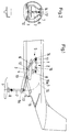
- FIG. 1 shows the two end positions of the device 2, on the one hand pivoted in the aircraft 1 and on the other hand after the complete pivoting out of the aircraft.
- the crane 5 moves with its lower arms 6 on the floor rail 4 from point 12 to point 13.
- an articulation point 14 located between arms 6 and 7 is moved in the direction of point 15.
- the articulation point 14 moves from the point 15 on a circular arc 16 until it has reached the end position shown.
- a cutout 9a is provided in the tailgate 9 for receiving the upper arm 7.
- the device 2 is shown in the uppermost position 16a of the circular arc 16 when it is pivoted out. It can be seen that directly below the hinge point 14 there is also a second hinge 17 which allows the upper arm 7 and thus the restraining head 8 to move in a plane transverse to the longitudinal direction of the device 2 or of the aircraft 1. This should make it easier for the drone 3 to retract into the capturing head 8.
- Fig. 3 the drone 3 is shown during the flight.
- a guide rod 21, the function of which is explained below, is retracted and secured by cover flaps 22. Furthermore, wings 23 are still visible.
- the guide rod 21 is e.g. brought in a not shown manner via a magnet-operated pawl by a spring body 24 in the extended position and locked there. The process takes place without supplying energy from the drone 3.
- the restraining head 8 is held on a rotatable attachment 7a with the pivot point 7b on the upper crane arm 7.
- the process of docking and resuming the drone 3 in the aircraft 1 takes place as follows: the drone 3 has returned to a predetermined point in time after being put down and after completing its task.
- Airplane 1 arrives at the destination in time and drives crane 2 with it the cessation head 8.
- the aircraft 1 is guided at a large distance in front of the drone 3, it being controlled, for example, with GPS.
- the aircraft 1 flies constantly at the docking speed.
- the drone 3 flies towards the aircraft from behind, controlled, for example, by difference signals sent from the aircraft to the drone (or by differential GPS). If the drone 3 is at a definable distance in front of the capturing head 8, the guide rod 21 is extended by a pre-programmed signal in the drone 3.
- FIG. 5 shows the structure of the restraining head 8 with claws for fastening the drone 3 and with the guide rod 21 retracted.
- the insertion of the guide rod 21 into the funnel 30 is supported by two centering arms 31 and by proximity switches 32.
- the centering arms 31 are articulated on a support plate 33, actuated via a dead position kinematics 34 and each driven by a hydraulic rotary motor 35.
- the outer ring 36 of an Elastoflex bearing 37 for the funnel 30 is suspended from parallelogram arms, which consist of a support arm 38 and a further arm 39.
- the parallelogram arms 38 and 39 are mounted in the shoulder 7a of the upper crane arm 7 and can be moved by an actuating cylinder 40, to facilitate insertion of the guide rod 21 into the funnel 30.
- the structure of the restraining head 8 has two supporting frames 41 and 42, which are connected by a semicircular shell 43.
- Two claws 44 are each mounted on the two supporting frames 41 and 42, which can grip around the rails 23 of the drone 3 in a manner not shown here and lock them.
- a hydraulic rotary motor 45 is provided for each claw 44.
- Dampers 45 are integrated into the rails 23 and brake the drone 3 via the claws 44 if the drone 3 has not previously been braked relative to the restraining head 8 due to the friction.
- At the end of the damper 45 which is indicated schematically by dashed lines, there is a damper stop 46.
Abstract
Description
Die Erfindung betrifft eine Vorrichtung zum Absetzen und Wiederaufhehmen einer Drohne von einem Transportflugzeug wahrend des Fluges.The invention relates to a device for depositing and resuming a drone from a transport aircraft during the flight.
Es ist bekannt, Drohnen mit Raketen, durch Flugzeugabwurf oder mit eigenem Triebwerk zu starten; letzteres setzt das Vorhandensein eines Fahrwerkes voraus. Die Landung erfolgt entweder auf dem Fahrwerk oder durch Entfalten von einem oder mehreren Fallschirmen.It is known to launch drones with rockets, by plane dropping or with their own engine; the latter presupposes the presence of a landing gear. The landing takes place either on the landing gear or by unfolding one or more parachutes.
Der Erfindung liegt die Aufgabe zugrunde, sowohl das Starten als auch das Landen einer Drohne mit Hilfe eines Transportflugzeuges durchzuführen.The invention has for its object to carry out both the launching and the landing of a drone using a transport aircraft.
Diese Aufgabe wird durch die im Anspruch 1 gekennzeichneten Merkmale gelöst. Vorteilhafte Ausgestaltungen der Erfindung sind in den Unteransprüchen gekennzeichnet.This object is achieved by the features characterized in
Die Vorrichtung hat dadurch, daß mit ihrer Hilfe eine Drohne von einem Transportflugzeug sowohl abgesetzt als auch wieder aufgenommen werden kann, für die Drohne mehrere Vorteile. Die Drohne braucht kein Fahrwerk und keine Fallschirmeinrichtungen. Die Tragflächen der Drohne können, weil sie nur bei hoher Geschwindigkeit fliegt, entsprechend Klein gehalten werden, und Landehilfen, wie z.B. Landeklappen, sind nicht erforderlich.The device has several advantages for the drone in that it can be used to drop and resume a drone from a transport aircraft. The drone needs no landing gear and no parachute equipment. The wings of the drone can be kept correspondingly small because they only fly at high speed, and landing aids such as Flaps are not required.
Die Erfindung wird nachstehend anhand der Zeichnung näher erläutert. Es zeigen:
- Fig. 1
- eine Längsansicht einer Vorrichtung zum Absetzen und Wiederaufnehmen einer Drohne, eingebaut in ein Transportflugzeug, in den beiden Endstellungen;
- Fig. 2
- eine Seitenansicht der Vorrichtung nach Fig. 1 beim Ausschwenken aus dem Transportflugzeug in der höchsten Schwenkstellung;
- Fig. 3
- eine Längsansicht der Drohne mit eingeklappter Führungsstange;
- Fig. 4
- die Drohne mit ausgeklappter Führungsstange kurz vor dem Einfahren in einen am oberen Kranarm der Vorrichtung angebrachten Fesselungskopf und
- Fig. 5
- die Struktur des Fesselungskopfes.
- Fig. 1
- a longitudinal view of a device for depositing and resuming a drone, installed in a transport aircraft, in the two end positions;
- Fig. 2
- a side view of the device of Figure 1 when swinging out of the transport plane in the highest pivot position.
- Fig. 3
- a longitudinal view of the drone with the guide rod folded;
- Fig. 4
- the drone with the guide rod folded out shortly before entering a fixation head attached to the upper crane arm of the device and
- Fig. 5
- the structure of the captive head.
Fig. 1 zeigt das Innere eines Transportflugzeuges 1, in dem eine Vorrichtung 2 zum Absetzen und Wiederaufhehmen einer Drohne 3 eingebaut ist. Die Vorrichtung 2 ist im Flugzeug 1 auf der Bodenstruktur gelagert und besteht aus einer Bodenschiene 4, einem Kran 5 mit zwei unteren Armen 6 (siehe Fig. 2) und einem oberen Arm 7 sowie aus einem an dem Kran 5 befestigten Fesselungskopf 8, in den die Drohne 3 einfahrbar und befestigbar ist. Die Arme 6 und 7 des Krans 5 sind so zueinander beweglich ausgebildet, daß sie nach dem Öffnen von Heckklappen 9 und 11 aus dem Flugzeug 1 ein- und ausfahren können und dabei auch die nötige Freiheit fuhr die Drohne 3 gewährleisten. Die Fig. 1 zeigt die beiden Endstellungen der Vorrichtung 2, und zwar zum einen eingeschwenkt im Flugzeug 1 und zum anderen nach dem vollständigen Ausschwenken aus dem Flugzeug. Wenn eine Drohne 3 abgesetzt werden soll, bewegt sich der Kran 5 mit seinen unteren Armen 6 auf der Bodenschiene 4 vom Punkt 12 zum Punkt 13. Dabei wird ein zwischen den Armen 6 und 7 befindlicher Gelenkpunkt 14 in Richtung nach dem Punkt 15 verschoben. Beim Ausschwenken der Drohne 3 bewegt sich der Gelenkpunkt 14 vom Punkt 15 auf einem Kreisbogen 16 bis er die gezeigte Endstellung erreicht hat. In der Heckklappe 9 ist zum Aufnehmen des oberen Armes 7 ein Ausschnitt 9a vorhanden.Fig. 1 shows the interior of a
In der Seitenansicht nach Fig. 2 ist die Vorrichtung 2 beim Ausschwenken in der obersten Stellung 16a des Kreisbogens 16 dargestellt. Man erkennt, daß direkt unterhalb des Gelenkpunktes 14 noch ein zweites Gelenk 17 vorhanden ist, das eine Bewegung des oberen Armes 7 und damit des Fesselungskopfes 8 in einer Ebene quer zur Längsrichtung der Vorrichtung 2 bzw. des Flugzeuges 1 erlaubt. Damit soll das Einfahren der Drohne 3 in den Fesselungskopf 8 erleichtert werden.In the side view according to FIG. 2, the
In Fig. 3 ist die Drohne 3 während des Fluges dargestellt. Dabei ist eine Führungsstange 21, deren Funktion weiter unten erläutert wird, eingefahren und durch Abdeckklappen 22 gesichert. Weiterhin sind noch Tragflächen 23 ersichtlich.In Fig. 3 the
Fig. 4 zeigt die Drohne 3 in Andockposition an den Fesselungskopf 8. Dabei sind die Abdeckklappen 22, die hier der Übersichtlichkeit halber nicht gezeigt sind, geöffnet und die Führungsstange 21 aus der gestrichelt dargestellten eingefahrenen Stellung nach oben ausgefahren. Durch eine strichpunktierte Linie 23 sind Schienen angedeutet, die auf der Drohne 3 seitlich der Führungsstange 21 angebracht sind und der Verriegelung mit dem Fesselungskopf 8 dienen. Die Führungsstange 21 wird z.B. in nicht dargesellter Weise über eine magnetbetätigte Klinke durch einen Federkörper 24 in die ausgefahrene Position gebracht und dort verriegelt. Der Vorgang erfolgt ohne Energiezufuhr aus der Drohne 3. Der Fesselungskopf 8 wird an einem drehbaren Ansatz 7a mit dem Drehpunkt 7b am oberen Kranarm 7 gehalten.4 shows the
Der Vorgang des Andockens und der Wiederaufnahme der Drohne 3 in das Flugzeug 1 erfolgt folgendermaßen: Die Drohne 3 ist nach dem Absetzen und nach der Erledigung ihrer Aufgabe zu einem vorgegebenen Zeitpunkt zurückgekehrt. Das Flugzeug 1 ist rechtzeitig am Zielort und Fährt den Kran 2 mit dem Fesselungskopf 8 aus. Das Flugzeug 1 wird dabei in einem großen Abstand vor die Drohne 3 geführt, wobei es z.B. mit GPS gesteuert wird. Das Flugzeug 1 fliegt konstant mit der Andockgeschwindigkeit. Die Drohne 3 fliegt von hinten auf das Flugzeug zu, gesteuert z.B. durch Differenzsignale, die vom Flugzeug zur Drohne gesendet werden (oder durch Differencial-GPS). Wenn sich die Drohne 3 in einem bestimmbaren Abstand vor dem Fesselungskopf 8 befindet, wird durch ein vorprogrammiertes Signal in der Drohne 3 die Führungsstange 21 ausgefahren. Kurz vor der Annäherung der Drohne 3 an den Fesselungskopf 8 wirken weitere Differenzsignale auf das Triebwerk und die Steuerflächen der Drohne 3 zur Verminderung ihrer Geschwindigkeit und zum Hin-führen an den Fesselungskopf 8 bis zum Einfahren der Führungsstange 21 in einen Trichter des Fesselungskopfes 8, wobei der Fesselungskopf auf die Führungsstange ausgerichtet wird. Diese Differenzsignale erfolgen durch ein zwischen dem Fesselungskopf 8 und der Führungsstange 21 vorhandenes Regelungssystem mit Sensoren. Nach dem fertigen Andocken wird die Flugregelung der Drohne abgeschaltet, das Triebwerk abgestellt und die Drohne 3 in ihrer Mittellage zentriert. Der gesamte Fesselungskopf 8 mit eingehängter und verriegelter Drohne 3 kann dann vom Kran 5 auf einer vorgegebenen Bahn in das Flugzeug 1 eingeschwenkt werden.The process of docking and resuming the
Fig. 5 zeigt die Struktur des Fesselungskopfes 8 mit Klauen zur Befestigung der Drohne 3 und bei eingefahrener Führungsstange 21. Das Einfahren der Führungsstange 21 in den Trichter 30 wird durch zwei Zentrierarme 31 und durch Näherungsschalter 32 unterstützt. Die Zentrierarme 31 sind an einer Tragplatte 33 angelenkt, über eine Totlagen-Kinematik 34 betätigt und jeweils von einem hydraulischen Drehmotor 35 angetrieben. Der Außenring 36 eines Elastoflexlagers 37 für den Trichter 30 ist an Parallelogrammarmen, die aus einem Tragarm 38 und einem weiteren Arm 39 bestehen, aufgehängt. Die Parallelogrammarme 38 und 39 sind in dem Ansatz 7a des oberen Kranarmes 7 gelagert und können von einem Stellzylinder 40 bewegt werden, um das Einführen der Führungsstange 21 in den Trichter 30 zu erleichtern. Die Struktur des Fesselungskopfes 8 weist zwei Tragspante 41 und 42 auf, die durch eine halbrunde Schale 43 verbunden sind. An den beiden Tragspanten 41 und 42 sind jeweils zwei Klauen 44 gelagert, die in hier nicht dargestellter Weise um die Schienen 23 der Drohne 3 greifen und diese verriegeln können. Fürjede Klaue 44 ist ein hydraulischer Drehmotor 45 vorgesehen. In die Schienen 23 sind Dämpfer 45 integriert, die die Drohne 3 über die Klauen 44 abbremsen, falls die Drohne 3 nicht vorher infolge der Reibung relativ zum Fesselungskopf 8 bereits abgebremst ist. Am Ende der Dämpfer 45, die hier schematisch gestrichelt angedeutet sind, ist ein Dämpfer-Anschlag 46 vorhanden.5 shows the structure of the
Claims (5)
Applications Claiming Priority (2)
| Application Number | Priority Date | Filing Date | Title |
|---|---|---|---|
| DE19602890A DE19602890C2 (en) | 1996-01-27 | 1996-01-27 | Device for depositing and resuming a drone |
| DE19602890 | 1996-01-27 |
Publications (2)
| Publication Number | Publication Date |
|---|---|
| EP0786403A1 true EP0786403A1 (en) | 1997-07-30 |
| EP0786403B1 EP0786403B1 (en) | 1999-10-27 |
Family
ID=7783823
Family Applications (1)
| Application Number | Title | Priority Date | Filing Date |
|---|---|---|---|
| EP97100748A Expired - Lifetime EP0786403B1 (en) | 1996-01-27 | 1997-01-18 | Drone launching and retrieval device |
Country Status (3)
| Country | Link |
|---|---|
| EP (1) | EP0786403B1 (en) |
| DE (1) | DE19602890C2 (en) |
| ES (1) | ES2138843T3 (en) |
Cited By (9)
| Publication number | Priority date | Publication date | Assignee | Title |
|---|---|---|---|---|
| US7793888B2 (en) | 2003-08-14 | 2010-09-14 | Nir Padan | Apparatus and method for air-to-air arming of aerial vehicles |
| WO2016097375A1 (en) * | 2014-12-19 | 2016-06-23 | Dae | Drone and associated airborne intervention equipment |
| CN106560396A (en) * | 2015-10-02 | 2017-04-12 | 英西图公司 | Aerial Launch And/or Recovery For Unmanned Aircraft, And Associated Systems And Methods |
| CN109552635A (en) * | 2018-12-20 | 2019-04-02 | 中国航空工业集团公司西安飞机设计研究所 | A kind of airborne electromagnetic formula unmanned plane recovery method and recyclable device |
| CN109747839A (en) * | 2018-12-27 | 2019-05-14 | 中国航空工业集团公司西安飞机设计研究所 | A kind of rigid space base unmanned plane recyclable device in tail portion and recovery method |
| CN109747830A (en) * | 2018-12-27 | 2019-05-14 | 中国航空工业集团公司西安飞机设计研究所 | A kind of single group wheel link-type unmanned plane delivery device and put-on method |
| US10589859B2 (en) | 2016-01-08 | 2020-03-17 | ST Engineering Aerospace Ltd. | Apparatus and method for aerial recovery of an unmanned aerial vehicle |
| US11414187B2 (en) | 2017-09-06 | 2022-08-16 | Hood Technology Corporation | Parasail-assisted systems and methods for launching and retrieving a fixed-wing aircraft into and from free flight |
| US11667398B2 (en) | 2017-09-06 | 2023-06-06 | Hood Technology Corporation | Multicopter-assisted systems and methods for launching and retrieving a fixed-wing aircraft into and from free flight |
Families Citing this family (3)
| Publication number | Priority date | Publication date | Assignee | Title |
|---|---|---|---|---|
| DE10313279B4 (en) * | 2003-03-25 | 2007-10-18 | Peter Zahner | Device for depositing aerodynamically unstable missiles from a transport aircraft |
| RU2495472C1 (en) * | 2012-10-24 | 2013-10-10 | Анатолий Николаевич Канцер | Method to escort kantser combat plane |
| CN109747842B (en) * | 2018-12-27 | 2022-05-17 | 中国航空工业集团公司西安飞机设计研究所 | Aerial recovery unit of unmanned aerial vehicle |
Citations (3)
| Publication number | Priority date | Publication date | Assignee | Title |
|---|---|---|---|---|
| GB546587A (en) * | 1941-08-09 | 1942-07-20 | Charles Dennistoun Burney | Improvements in or relating to heavier-than-air aircraft |
| US3088693A (en) * | 1961-09-15 | 1963-05-07 | Hayes Corp | Towed target launching and retrieval apparatus |
| US3520502A (en) * | 1968-11-12 | 1970-07-14 | Lockheed Aircraft Corp | Cargo launching and recovery apparatus for aircraft |
Family Cites Families (2)
| Publication number | Priority date | Publication date | Assignee | Title |
|---|---|---|---|---|
| US2921756A (en) * | 1956-04-20 | 1960-01-19 | Goodyear Aircraft Corp | Composite aircraft |
| GB926613A (en) * | 1958-04-14 | 1963-05-22 | English Electric Co Ltd | Improvements in and relating to composite vertical take-off aircraft |
-
1996
- 1996-01-27 DE DE19602890A patent/DE19602890C2/en not_active Expired - Fee Related
-
1997
- 1997-01-18 EP EP97100748A patent/EP0786403B1/en not_active Expired - Lifetime
- 1997-01-18 ES ES97100748T patent/ES2138843T3/en not_active Expired - Lifetime
Patent Citations (3)
| Publication number | Priority date | Publication date | Assignee | Title |
|---|---|---|---|---|
| GB546587A (en) * | 1941-08-09 | 1942-07-20 | Charles Dennistoun Burney | Improvements in or relating to heavier-than-air aircraft |
| US3088693A (en) * | 1961-09-15 | 1963-05-07 | Hayes Corp | Towed target launching and retrieval apparatus |
| US3520502A (en) * | 1968-11-12 | 1970-07-14 | Lockheed Aircraft Corp | Cargo launching and recovery apparatus for aircraft |
Cited By (17)
| Publication number | Priority date | Publication date | Assignee | Title |
|---|---|---|---|---|
| US7793888B2 (en) | 2003-08-14 | 2010-09-14 | Nir Padan | Apparatus and method for air-to-air arming of aerial vehicles |
| WO2016097375A1 (en) * | 2014-12-19 | 2016-06-23 | Dae | Drone and associated airborne intervention equipment |
| CN107743469A (en) * | 2014-12-19 | 2018-02-27 | 达鄂公司 | The aerial intervention apparatu of UAV and correlation |
| US10793271B2 (en) | 2014-12-19 | 2020-10-06 | Dae | Drone and associated airborne intervention equipment |
| CN106560396A (en) * | 2015-10-02 | 2017-04-12 | 英西图公司 | Aerial Launch And/or Recovery For Unmanned Aircraft, And Associated Systems And Methods |
| US11858631B2 (en) | 2015-10-02 | 2024-01-02 | Insitu, Inc. | Aerial launch and/or recovery for unmanned aircraft with submersible devices, and associated systems and methods |
| US10933997B2 (en) | 2015-10-02 | 2021-03-02 | Insitu, Inc. | Aerial launch and/or recovery for unmanned aircraft, and associated systems and methods |
| CN106560396B (en) * | 2015-10-02 | 2021-11-30 | 英西图公司 | Aerial launch and/or recovery of unmanned aerial vehicles and related systems and methods |
| US10589859B2 (en) | 2016-01-08 | 2020-03-17 | ST Engineering Aerospace Ltd. | Apparatus and method for aerial recovery of an unmanned aerial vehicle |
| US11414187B2 (en) | 2017-09-06 | 2022-08-16 | Hood Technology Corporation | Parasail-assisted systems and methods for launching and retrieving a fixed-wing aircraft into and from free flight |
| US11667398B2 (en) | 2017-09-06 | 2023-06-06 | Hood Technology Corporation | Multicopter-assisted systems and methods for launching and retrieving a fixed-wing aircraft into and from free flight |
| US11639236B2 (en) | 2017-09-06 | 2023-05-02 | Hood Technology Corporation | Apparatus and method for launching a fixed-wing aircraft into free flight |
| CN109552635A (en) * | 2018-12-20 | 2019-04-02 | 中国航空工业集团公司西安飞机设计研究所 | A kind of airborne electromagnetic formula unmanned plane recovery method and recyclable device |
| CN109747830B (en) * | 2018-12-27 | 2022-04-19 | 中国航空工业集团公司西安飞机设计研究所 | Single-group wheel connecting rod type unmanned aerial vehicle throwing device and throwing method |
| CN109747839B (en) * | 2018-12-27 | 2022-04-19 | 中国航空工业集团公司西安飞机设计研究所 | Tail hard type air-based unmanned aerial vehicle recovery device and recovery method |
| CN109747830A (en) * | 2018-12-27 | 2019-05-14 | 中国航空工业集团公司西安飞机设计研究所 | A kind of single group wheel link-type unmanned plane delivery device and put-on method |
| CN109747839A (en) * | 2018-12-27 | 2019-05-14 | 中国航空工业集团公司西安飞机设计研究所 | A kind of rigid space base unmanned plane recyclable device in tail portion and recovery method |
Also Published As
| Publication number | Publication date |
|---|---|
| EP0786403B1 (en) | 1999-10-27 |
| DE19602890A1 (en) | 1997-07-31 |
| DE19602890C2 (en) | 1998-10-22 |
| ES2138843T3 (en) | 2000-01-16 |
Similar Documents
| Publication | Publication Date | Title |
|---|---|---|
| EP0786403B1 (en) | Drone launching and retrieval device | |
| DE102010010508A1 (en) | Unmanned aircraft for carrying and throwing missiles, comprises cargo space, which is closed in outer side with hatch, where hatch opens downward, such that cargo elements are ejected downward from cargo space | |
| DE4301671A1 (en) | Recovery system for drone etc. - has catch line held in frame to lock into hook held above drone, with retarding mounting for line. | |
| EP0063096B1 (en) | Pneumatic tube station with a joint tube rotatable into transit, despatch and delivery positions | |
| EP0141895B1 (en) | Aircraft with wings foldable by pivoting | |
| EP0943541B1 (en) | Launcher device for a towed flying body | |
| WO2012066085A1 (en) | Towing an aircraft having a landing gear adapter (method and device) | |
| EP1359091B1 (en) | Load dropping system with parachute | |
| DE3215434A1 (en) | Locking mechanism for unfoldable solar generators of satellites | |
| DE3302771A1 (en) | Towing vehicle for aircraft | |
| EP0220687B1 (en) | Method and apparatus for opening and/or closing the bonnets of automotive-vehicle bodies | |
| DE202015004305U1 (en) | Device for opening and closing one or more nose flaps, in particular for rail vehicles | |
| DE1531353C3 (en) | Device for adjusting a wing member in a swing-wing aircraft | |
| EP3647209B1 (en) | Capture device and capture method for catching uncooperative satellites in space | |
| EP0459188B1 (en) | Wing, deployable from an airborne body | |
| DE10303788A1 (en) | Load-bearing system with a load shield and a method for stabilizing a load-sharing system with a load shield after landing from the aircraft | |
| EP4239276A1 (en) | Support platform for launching or dropping an unmanned aerial vehicle onto a target and method for operating such a support platform | |
| EP3161308A1 (en) | System for starting and landing a flight-capable wing construction | |
| AT244862B (en) | Device for jigs in hydraulic engineering closures | |
| DE2641942B1 (en) | Locking device for weighing container | |
| DE2754884A1 (en) | Load securing clamps for aircraft - operate with recessed sprung levers to grip slides of load | |
| DE2641942C (en) | Closing device for weighing containers | |
| DE2057335A1 (en) | Device for retracting and extending the landing gear of aircraft | |
| DE1164834B (en) | Airplane with a rotor head arranged thereon for the purpose of rotational movement and with a streamlined fairing | |
| DE2844718A1 (en) | Passenger rescue system for suspension railways or lift cars - has lock with spring-loaded horizontally movable slide piece with shoulder engaging with lower cover |
Legal Events
| Date | Code | Title | Description |
|---|---|---|---|
| PUAI | Public reference made under article 153(3) epc to a published international application that has entered the european phase |
Free format text: ORIGINAL CODE: 0009012 |
|
| AK | Designated contracting states |
Kind code of ref document: A1 Designated state(s): ES FR GB IT |
|
| 17P | Request for examination filed |
Effective date: 19970816 |
|
| 17Q | First examination report despatched |
Effective date: 19980925 |
|
| GRAG | Despatch of communication of intention to grant |
Free format text: ORIGINAL CODE: EPIDOS AGRA |
|
| GRAG | Despatch of communication of intention to grant |
Free format text: ORIGINAL CODE: EPIDOS AGRA |
|
| GRAH | Despatch of communication of intention to grant a patent |
Free format text: ORIGINAL CODE: EPIDOS IGRA |
|
| GRAH | Despatch of communication of intention to grant a patent |
Free format text: ORIGINAL CODE: EPIDOS IGRA |
|
| GRAA | (expected) grant |
Free format text: ORIGINAL CODE: 0009210 |
|
| RAP1 | Party data changed (applicant data changed or rights of an application transferred) |
Owner name: DAIMLERCHRYSLER AG |
|
| AK | Designated contracting states |
Kind code of ref document: B1 Designated state(s): ES FR GB IT |
|
| REG | Reference to a national code |
Ref country code: ES Ref legal event code: FG2A Ref document number: 2138843 Country of ref document: ES Kind code of ref document: T3 |
|
| ITF | It: translation for a ep patent filed |
Owner name: STUDIO JAUMANN P. & C. S.N.C. |
|
| ET | Fr: translation filed | ||
| GBT | Gb: translation of ep patent filed (gb section 77(6)(a)/1977) |
Effective date: 20000127 |
|
| PLBE | No opposition filed within time limit |
Free format text: ORIGINAL CODE: 0009261 |
|
| STAA | Information on the status of an ep patent application or granted ep patent |
Free format text: STATUS: NO OPPOSITION FILED WITHIN TIME LIMIT |
|
| 26N | No opposition filed | ||
| REG | Reference to a national code |
Ref country code: GB Ref legal event code: IF02 |
|
| PGFP | Annual fee paid to national office [announced via postgrant information from national office to epo] |
Ref country code: ES Payment date: 20030124 Year of fee payment: 7 |
|
| PG25 | Lapsed in a contracting state [announced via postgrant information from national office to epo] |
Ref country code: ES Free format text: LAPSE BECAUSE OF NON-PAYMENT OF DUE FEES Effective date: 20040119 |
|
| PG25 | Lapsed in a contracting state [announced via postgrant information from national office to epo] |
Ref country code: IT Free format text: LAPSE BECAUSE OF NON-PAYMENT OF DUE FEES;WARNING: LAPSES OF ITALIAN PATENTS WITH EFFECTIVE DATE BEFORE 2007 MAY HAVE OCCURRED AT ANY TIME BEFORE 2007. THE CORRECT EFFECTIVE DATE MAY BE DIFFERENT FROM THE ONE RECORDED. Effective date: 20050118 |
|
| REG | Reference to a national code |
Ref country code: ES Ref legal event code: FD2A Effective date: 20040119 |
|
| PGFP | Annual fee paid to national office [announced via postgrant information from national office to epo] |
Ref country code: FR Payment date: 20110202 Year of fee payment: 15 |
|
| PGFP | Annual fee paid to national office [announced via postgrant information from national office to epo] |
Ref country code: GB Payment date: 20110120 Year of fee payment: 15 |
|
| GBPC | Gb: european patent ceased through non-payment of renewal fee |
Effective date: 20120118 |
|
| REG | Reference to a national code |
Ref country code: FR Ref legal event code: ST Effective date: 20120928 |
|
| PG25 | Lapsed in a contracting state [announced via postgrant information from national office to epo] |
Ref country code: GB Free format text: LAPSE BECAUSE OF NON-PAYMENT OF DUE FEES Effective date: 20120118 |
|
| PG25 | Lapsed in a contracting state [announced via postgrant information from national office to epo] |
Ref country code: FR Free format text: LAPSE BECAUSE OF NON-PAYMENT OF DUE FEES Effective date: 20120131 |