EP0785562B1 - Lastschalter mit Kontakten mit Doppelbewegung - Google Patents
Lastschalter mit Kontakten mit Doppelbewegung Download PDFInfo
- Publication number
- EP0785562B1 EP0785562B1 EP97400084A EP97400084A EP0785562B1 EP 0785562 B1 EP0785562 B1 EP 0785562B1 EP 97400084 A EP97400084 A EP 97400084A EP 97400084 A EP97400084 A EP 97400084A EP 0785562 B1 EP0785562 B1 EP 0785562B1
- Authority
- EP
- European Patent Office
- Prior art keywords
- tube
- piston
- contacts
- circuit breaker
- semi
- Prior art date
- Legal status (The legal status is an assumption and is not a legal conclusion. Google has not performed a legal analysis and makes no representation as to the accuracy of the status listed.)
- Expired - Lifetime
Links
Images


Classifications
-
- H—ELECTRICITY
- H01—ELECTRIC ELEMENTS
- H01H—ELECTRIC SWITCHES; RELAYS; SELECTORS; EMERGENCY PROTECTIVE DEVICES
- H01H33/00—High-tension or heavy-current switches with arc-extinguishing or arc-preventing means
- H01H33/70—Switches with separate means for directing, obtaining, or increasing flow of arc-extinguishing fluid
- H01H33/88—Switches with separate means for directing, obtaining, or increasing flow of arc-extinguishing fluid the flow of arc-extinguishing fluid being produced or increased by movement of pistons or other pressure-producing parts
- H01H33/90—Switches with separate means for directing, obtaining, or increasing flow of arc-extinguishing fluid the flow of arc-extinguishing fluid being produced or increased by movement of pistons or other pressure-producing parts this movement being effected by or in conjunction with the contact-operating mechanism
- H01H33/904—Switches with separate means for directing, obtaining, or increasing flow of arc-extinguishing fluid the flow of arc-extinguishing fluid being produced or increased by movement of pistons or other pressure-producing parts this movement being effected by or in conjunction with the contact-operating mechanism characterised by the transmission between operating mechanism and piston or movable contact
-
- H—ELECTRICITY
- H01—ELECTRIC ELEMENTS
- H01H—ELECTRIC SWITCHES; RELAYS; SELECTORS; EMERGENCY PROTECTIVE DEVICES
- H01H33/00—High-tension or heavy-current switches with arc-extinguishing or arc-preventing means
- H01H33/02—Details
- H01H2033/028—Details the cooperating contacts being both actuated simultaneously in opposite directions
Definitions
- the present invention relates to a circuit breaker with high voltage double movement of the contacts.
- An object of the present invention is to design a circuit breaker with double movement of contacts not comprising no connecting rods, so that the inside diameter of the cut-off chamber is reduced as much as possible.
- Another object of the invention is to provide a circuit breaker with double movement of the contacts, in which the operating energy, upon opening, is as reduced as possible.
- circuit breaker the invention which relates to a high voltage circuit breaker double movement of the contacts, comprising, for each pole, an insulating jacket filled with insulating gas and containing a movable assembly comprising contacts contacts, arcing contacts, and a blow cylinder cooperating with a fixed blow piston, and an assembly semi-mobile including permanent contacts and arcing contacts, characterized in that the movement of the semi-mobile assembly is obtained by a system with vacuum including a vacuum cylinder to inside which a first piston can move secured to the mobile assembly and a second piston connected to the semi-mobile assembly.
- the vacuum cylinder is consisting of a fixed cylindrical portion arranged coaxially and around a tube constituting the contact permanent semi-mobile.
- the second piston has a tubular rod internally containing at at least one rack element cooperating with at least one fixed gear itself cooperating with an element of rack fixed internally to said tube constituting the semi-mobile permanent contact.
- the second piston comprises a rod integral with said tube constituting the semi-mobile permanent contact and provided at its end with a shoulder used to support a first end of a spring whose second end bears on a stop integral with said cylindrical portion forming with said tube said vacuum cylinder.
- circuit breakers i.e. intended to be placed outdoors.
- circuit breakers include a envelope in ceramic or synthetic material.
- circuit breakers of the metal casing type with the earth also known by the terminology of shielded circuit breakers.
- reference 1 designates an envelope, partially shown, for example ceramic.
- This envelope is waterproof and closed with metal flanges not shown and carrying sockets not represented.
- the envelope is filled with an insulating gas, for example sulfur hexafluoride SF6, under a pressures of a few bars.
- the set of semi-mobile contacts includes a contact for the passage of permanent current, consisting of a metal tube 2; this tube is guided in a bore of a fixed metal part 3 electrically connected to the first socket outlet not shown.
- Sliding contacts 4 for example of the "accordion" type, ensure the passage of the current between part 3 and tube 2.
- the tube 2 is integral with a tube 6, arranged internally and coaxially with the tube 2, and constituting the arcing contact of the semi-mobile contact assembly.
- the tube 2 and tube 6 constitute the same part coming from foundry and are connected by a crown 7 provided with holes 7A for the passage of gas.
- the end of the tube 6 is provided a 6A tip made of an alloy resistant to the effects of the electric arc.
- the mobile assembly includes a tube 9 extended to a end by a ring of contact fingers 10; the tube 9 slides into a bore of a fixed metal part 12 electrically connected to the second outlet not represented.
- Sliding contacts 14, for example of the type "accordion”, ensure the passage of current between the room 12 and tube 9.
- the tube 9 is integral with a tube 16, arranged internally and coaxially with the tube 9, and constituting the arcing contact of the movable contact assembly.
- Tube 9 and the tube 16 are connected by a crown 17 provided with holes 17A for the passage of gas.
- the end of the tube 16 is fitted with a 16A tip made of a resistant alloy to the effects of the electric arc.
- the tube 16 passes through a fixed blow piston 18, of annular section, placed in the movable section cylinder annular formed by tubes 9 and 16.
- Tubes 9 and 16, the piston 18 and the crown 17 define a volume of blowing; compressed gas during a trigger, is pushed towards the end of the movable contact arc 16A and passes through a blowing nozzle 20 of material insulating.
- the tube 16 is connected to the end of a rod of maneuver not shown actuated by a command not represented.
- pistons 23 and 26 are provided with seals, not referenced, to create a seal with the cylinder in which they slide.
- the engagement is carried out by displacement of the moving crew, under the action of the command, towards the left of the figures. It is possible to provide, in the piston 26, a one-way valve 26A which avoids an overpressure in the volume between the pistons 23 and 26.
- the system performing the double movement that comes to be described is economical, can be placed on existing circuit breakers and occupies a small volume since its diameter does not exceed that of the metal parts 3 and 12.
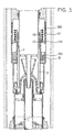
- Figs. 4 to 6 relate to an alternative embodiment in which the movement of the moving assembly in direction opposite to that of the moving crew only intervenes after a phase of compression of the blowing gas; this gas precompression ensures an increase in the power of breaker breaker.
- the elements common to Figs. 1 to 3 and in Figs. 4 to 6 received the same reference numbers.
- the piston rod 26 is modified.
- This rod, referenced 40 is a tubular portion secured to the tube 2 and includes a terminal shoulder 40A.
- a first end of a spring 42 bears against the shoulder 40A; the second end of the spring 42 comes to bear against an annular stop 43 bearing on the cylinder 21.
- the stop 43 is provided with holes 43A for the passage of gas.
- the device described in this variant presents the same advantages as that described above.
- the gas precompression before contact separation favors breaking of the current, in particular of the currents capacitive.
- the invention applies to high circuit breakers tension, open type or metal casing type to Earth.
Landscapes
- Circuit Breakers (AREA)
- Keying Circuit Devices (AREA)
- Push-Button Switches (AREA)
- Driving Mechanisms And Operating Circuits Of Arc-Extinguishing High-Tension Switches (AREA)
Claims (4)
- Hochspannungslastschalter mit Doppelbewegung der Kontakte, umfassend für jeden Pol eine isolierende Hülle (1), die mit Isolierungsgas gefüllt ist, und enthaltend eine bewegliche Anordnung mit Permanentkontakten (10), Bogenkontakten (16A) und einen Blaszylinder (9 - 16), der mit einem feststehenden Blaszylinder (18) wechselwirkt, und eine halbbewegliche Anordnung mit Permanentkontakten (2) und Bogenkontakten (6A), dadurch gekennzeichnet, dass die Bewegung der halbbeweglichen Anordnung erhalten wird durch ein Unterdrucksystem, umfassend einen Unterdruckzylinder (2 - 21) im Inneren, von welchem sich ein erster Kolben (23), verbunden mit der beweglichen Anordnung und ein zweiter Kolben (26), verbunden mit der halbbeweglichen Anordnung bewegen können.
- Lastschalter nach Anspruch 1, dadurch gekennzeichnet, dass der Unterdruckzylinder gebildet ist durch einen feststehenden zylindrischen Abschnitt (21), koaxial angeordnet und herum um ein Rohr (2), welches den halbbeweglichen Permanentkontakt bildet.
- Lastschalter nach Anspruch 2, dadurch gekennzeichnet, dass der zweite Kolben (26) einen tubusartigen Schaft (27) umfasst, innerlich zumindest ein Zahnstangenelement (28, 28A) enthaltend, welches mit zumindest einem feststehenden Stirnrad (30, 31) wechselwirkt, welches wiederum mit einem Zahnstangenelement (29, 29A) wechselwirkt, innerlich an dem Rohr (2) befestigt, welches den halbbeweglichen Permanentkontakt bildet.
- Lastschalter nach Anspruch 2, dadurch gekennzeichnet, dass der zweite Kolben (26) einen Schaft (40) umfasst, der mit dem Rohr (2) verbunden ist, welches den halbbeweglichen Permanentkontakt bildet und an seinem Ende mit einer Vorkragung (40A) versehen ist, die als Anlage für ein erstes Ende einer Feder (42) dient, deren zweites Ende in Anlage gelangt an einen Anschlag (43), der mit dem zylindrischen Abschnitt (21) verbunden ist, welcher mit dem Rohr (2) den Unterdruckzylinder bildet.
Applications Claiming Priority (2)
| Application Number | Priority Date | Filing Date | Title |
|---|---|---|---|
| FR9600664A FR2743936B1 (fr) | 1996-01-22 | 1996-01-22 | Disjonteur a double mouvement des contacts |
| FR9600664 | 1996-01-22 |
Publications (2)
| Publication Number | Publication Date |
|---|---|
| EP0785562A1 EP0785562A1 (de) | 1997-07-23 |
| EP0785562B1 true EP0785562B1 (de) | 2001-11-28 |
Family
ID=9488317
Family Applications (1)
| Application Number | Title | Priority Date | Filing Date |
|---|---|---|---|
| EP97400084A Expired - Lifetime EP0785562B1 (de) | 1996-01-22 | 1997-01-16 | Lastschalter mit Kontakten mit Doppelbewegung |
Country Status (4)
| Country | Link |
|---|---|
| EP (1) | EP0785562B1 (de) |
| AT (1) | ATE209827T1 (de) |
| DE (1) | DE69708466T2 (de) |
| FR (1) | FR2743936B1 (de) |
Families Citing this family (8)
| Publication number | Priority date | Publication date | Assignee | Title |
|---|---|---|---|---|
| FR2769403B1 (fr) * | 1997-10-02 | 1999-11-12 | Gec Alsthom T & D Sa | Interrupteur a gaz comprime avec un engrenage a cremailleres |
| DE19928080C5 (de) * | 1999-06-11 | 2006-11-16 | Siemens Ag | Hochspannungsleistungsschalter mit einem Abströmkanal |
| EP1879207B1 (de) * | 2006-07-12 | 2017-04-19 | ABB Schweiz AG | Zahnstangengetriebe für elektrisches Schaltgerät |
| WO2012011119A1 (en) * | 2010-07-20 | 2012-01-26 | Bharat Heavy Electricals Limited | Pressure propelled contact system for gas circuit breaker interrupter |
| CN105551883B (zh) * | 2016-02-19 | 2018-06-12 | 浙江开关厂有限公司 | 双向吹气灭弧室 |
| DE102016218518C5 (de) * | 2016-09-27 | 2023-05-11 | Siemens Energy Global GmbH & Co. KG | Kontaktstück für einen Hochspannungs-Leistungsschalter sowie Verfahren zu dessen Herstellung |
| CN114420480B (zh) * | 2022-01-06 | 2023-12-08 | 平高集团有限公司 | 具有隔离断口的高压开关设备及其动触头组件 |
| EP4481785A1 (de) | 2023-06-20 | 2024-12-25 | Hitachi Energy Ltd | Schaltgerät |
Family Cites Families (3)
| Publication number | Priority date | Publication date | Assignee | Title |
|---|---|---|---|---|
| DE2626435A1 (de) * | 1976-06-12 | 1977-12-22 | Merlin Gerin | Druckgasschalter |
| FR2696316B1 (fr) * | 1992-10-06 | 1994-11-04 | Alsthom Gec | Disjoncteur à haute ou moyenne tension à expansion thermique et soufflage additionnel par aspiration. |
| FR2715500B1 (fr) * | 1994-01-25 | 1996-02-16 | Gec Alsthom T & D Sa | Disjoncteur à auto-soufflage et à double mouvement. |
-
1996
- 1996-01-22 FR FR9600664A patent/FR2743936B1/fr not_active Expired - Fee Related
-
1997
- 1997-01-16 DE DE69708466T patent/DE69708466T2/de not_active Expired - Fee Related
- 1997-01-16 AT AT97400084T patent/ATE209827T1/de not_active IP Right Cessation
- 1997-01-16 EP EP97400084A patent/EP0785562B1/de not_active Expired - Lifetime
Also Published As
| Publication number | Publication date |
|---|---|
| ATE209827T1 (de) | 2001-12-15 |
| FR2743936B1 (fr) | 1998-02-20 |
| DE69708466T2 (de) | 2002-07-04 |
| FR2743936A1 (fr) | 1997-07-25 |
| DE69708466D1 (de) | 2002-01-10 |
| EP0785562A1 (de) | 1997-07-23 |
Similar Documents
| Publication | Publication Date | Title |
|---|---|---|
| CA2053951C (fr) | Disjoncteur a sf6 a condensateur incorpore | |
| CA2035688C (fr) | Disjoncteur a moyenne ou haute tension a autosoufflage | |
| EP0785562B1 (de) | Lastschalter mit Kontakten mit Doppelbewegung | |
| EP0591039B1 (de) | Hochspannung selbst-Blaslastscharter mit Schnittkammer mit reduzierter Gaskompression | |
| FR2512267A1 (fr) | Disjoncteur a gaz comprime muni de resistances d'ouverture et de fermeture | |
| FR2790592A1 (fr) | Disjoncteur haute tension a double mouvement | |
| CA2206950C (fr) | Disjoncteur a haute tension avec insertion de resistance a la fermeture. | |
| FR2619246A1 (fr) | Disjoncteur a haute ou moyenne tension a gaz sous pression a energie de coupure prelevee sur celle de l'arc | |
| FR2576144A1 (fr) | Disjoncteur a haute tension, a gaz comprime, a faible energie de manoeuvre | |
| EP0759629B1 (de) | Lastschalter mit Einschaltwiderstand und Einfügungsvorrichtung | |
| FR2576143A1 (fr) | Disjoncteur a haute tension, a gaz comprime, a energie de manoeuvre assistee par l'effet thermique de l'arc et a double mouvement | |
| EP0450567B1 (de) | Hoch- oder Mittelspannungs-Schalter mit aufeinanderstossenden Lichtbogenkontakten | |
| EP0398213B1 (de) | Mittelspannungsschalter für hohen Nennstrom | |
| EP0831503B1 (de) | Hochspannungs-Lastschalter mit Dämpfer | |
| EP0664552A1 (de) | Autopneumatischer Druckgasschalter mit Doppelbewegung | |
| FR2535518A1 (fr) | Chambre de coupure pour disjoncteur a gaz | |
| EP0515268A1 (de) | Varistor Einführvorrichtung, eingebaut in einem Hochspannungslastschalter | |
| FR2662540A1 (fr) | Disjoncteur a moyenne tension. | |
| FR2737937A1 (fr) | Disjoncteur a double mouvement avec resistance de fermeture | |
| FR2694987A1 (fr) | Disjoncteur à haute tension ayant une chambre de coupure à volume de soufflage variable. | |
| CA1251818A (fr) | Disjoncteur haute tension a soufflage d'arc | |
| FR2657459A1 (fr) | Disjoncteur a haute tension a resistance de fermeture. | |
| FR2556496A1 (fr) | Disjoncteur a gaz comprime | |
| FR2658949A1 (fr) | Disjoncteur a coupure assistee par varistance. | |
| FR2949170A1 (fr) | Chambre de coupure pour disjoncteur a moyenne ou haute tension a energie de manœuvre reduite |
Legal Events
| Date | Code | Title | Description |
|---|---|---|---|
| PUAI | Public reference made under article 153(3) epc to a published international application that has entered the european phase |
Free format text: ORIGINAL CODE: 0009012 |
|
| AK | Designated contracting states |
Kind code of ref document: A1 Designated state(s): AT CH DE ES GB IT LI SE |
|
| 17P | Request for examination filed |
Effective date: 19971204 |
|
| GRAG | Despatch of communication of intention to grant |
Free format text: ORIGINAL CODE: EPIDOS AGRA |
|
| GRAG | Despatch of communication of intention to grant |
Free format text: ORIGINAL CODE: EPIDOS AGRA |
|
| GRAH | Despatch of communication of intention to grant a patent |
Free format text: ORIGINAL CODE: EPIDOS IGRA |
|
| 17Q | First examination report despatched |
Effective date: 20010411 |
|
| GRAH | Despatch of communication of intention to grant a patent |
Free format text: ORIGINAL CODE: EPIDOS IGRA |
|
| GRAA | (expected) grant |
Free format text: ORIGINAL CODE: 0009210 |
|
| AK | Designated contracting states |
Kind code of ref document: B1 Designated state(s): AT CH DE ES GB IT LI SE |
|
| PG25 | Lapsed in a contracting state [announced via postgrant information from national office to epo] |
Ref country code: IT Free format text: LAPSE BECAUSE OF FAILURE TO SUBMIT A TRANSLATION OF THE DESCRIPTION OR TO PAY THE FEE WITHIN THE PRESCRIBED TIME-LIMIT;WARNING: LAPSES OF ITALIAN PATENTS WITH EFFECTIVE DATE BEFORE 2007 MAY HAVE OCCURRED AT ANY TIME BEFORE 2007. THE CORRECT EFFECTIVE DATE MAY BE DIFFERENT FROM THE ONE RECORDED. Effective date: 20011128 Ref country code: AT Free format text: LAPSE BECAUSE OF FAILURE TO SUBMIT A TRANSLATION OF THE DESCRIPTION OR TO PAY THE FEE WITHIN THE PRESCRIBED TIME-LIMIT Effective date: 20011128 |
|
| REF | Corresponds to: |
Ref document number: 209827 Country of ref document: AT Date of ref document: 20011215 Kind code of ref document: T |
|
| REG | Reference to a national code |
Ref country code: CH Ref legal event code: EP |
|
| PGFP | Annual fee paid to national office [announced via postgrant information from national office to epo] |
Ref country code: GB Payment date: 20011214 Year of fee payment: 6 |
|
| PGFP | Annual fee paid to national office [announced via postgrant information from national office to epo] |
Ref country code: CH Payment date: 20011217 Year of fee payment: 6 Ref country code: DE Payment date: 20011217 Year of fee payment: 6 |
|
| GBT | Gb: translation of ep patent filed (gb section 77(6)(a)/1977) |
Effective date: 20011128 |
|
| REG | Reference to a national code |
Ref country code: CH Ref legal event code: NV Representative=s name: CABINET ROLAND NITHARDT CONSEILS EN PROPRIETE INDU |
|
| REG | Reference to a national code |
Ref country code: GB Ref legal event code: IF02 |
|
| REF | Corresponds to: |
Ref document number: 69708466 Country of ref document: DE Date of ref document: 20020110 |
|
| PG25 | Lapsed in a contracting state [announced via postgrant information from national office to epo] |
Ref country code: SE Free format text: LAPSE BECAUSE OF FAILURE TO SUBMIT A TRANSLATION OF THE DESCRIPTION OR TO PAY THE FEE WITHIN THE PRESCRIBED TIME-LIMIT Effective date: 20020228 |
|
| PG25 | Lapsed in a contracting state [announced via postgrant information from national office to epo] |
Ref country code: ES Free format text: LAPSE BECAUSE OF FAILURE TO SUBMIT A TRANSLATION OF THE DESCRIPTION OR TO PAY THE FEE WITHIN THE PRESCRIBED TIME-LIMIT Effective date: 20020530 |
|
| PLBE | No opposition filed within time limit |
Free format text: ORIGINAL CODE: 0009261 |
|
| STAA | Information on the status of an ep patent application or granted ep patent |
Free format text: STATUS: NO OPPOSITION FILED WITHIN TIME LIMIT |
|
| 26N | No opposition filed | ||
| PG25 | Lapsed in a contracting state [announced via postgrant information from national office to epo] |
Ref country code: GB Free format text: LAPSE BECAUSE OF NON-PAYMENT OF DUE FEES Effective date: 20030116 |
|
| PG25 | Lapsed in a contracting state [announced via postgrant information from national office to epo] |
Ref country code: LI Free format text: LAPSE BECAUSE OF NON-PAYMENT OF DUE FEES Effective date: 20030131 Ref country code: CH Free format text: LAPSE BECAUSE OF NON-PAYMENT OF DUE FEES Effective date: 20030131 |
|
| PG25 | Lapsed in a contracting state [announced via postgrant information from national office to epo] |
Ref country code: DE Free format text: LAPSE BECAUSE OF NON-PAYMENT OF DUE FEES Effective date: 20030801 |
|
| GBPC | Gb: european patent ceased through non-payment of renewal fee | ||
| REG | Reference to a national code |
Ref country code: CH Ref legal event code: PL |