EP0785480B1 - Rouleau d'entraínement de commande et de tension pour les bandes de ruban - Google Patents
Rouleau d'entraínement de commande et de tension pour les bandes de ruban Download PDFInfo
- Publication number
- EP0785480B1 EP0785480B1 EP97300143A EP97300143A EP0785480B1 EP 0785480 B1 EP0785480 B1 EP 0785480B1 EP 97300143 A EP97300143 A EP 97300143A EP 97300143 A EP97300143 A EP 97300143A EP 0785480 B1 EP0785480 B1 EP 0785480B1
- Authority
- EP
- European Patent Office
- Prior art keywords
- belt
- roller
- axis
- steering
- utility
- Prior art date
- Legal status (The legal status is an assumption and is not a legal conclusion. Google has not performed a legal analysis and makes no representation as to the accuracy of the status listed.)
- Expired - Lifetime
Links
- 108091008695 photoreceptors Proteins 0.000 claims description 28
- 230000033001 locomotion Effects 0.000 claims description 25
- 238000012545 processing Methods 0.000 claims description 6
- 230000005540 biological transmission Effects 0.000 claims description 3
- 230000004044 response Effects 0.000 claims description 2
- 230000000694 effects Effects 0.000 claims 1
- 239000000463 material Substances 0.000 description 11
- 238000000034 method Methods 0.000 description 10
- 230000007246 mechanism Effects 0.000 description 8
- 239000000843 powder Substances 0.000 description 8
- 238000012546 transfer Methods 0.000 description 8
- 239000002245 particle Substances 0.000 description 6
- 230000008569 process Effects 0.000 description 6
- 238000011161 development Methods 0.000 description 5
- 238000003384 imaging method Methods 0.000 description 5
- 238000013461 design Methods 0.000 description 3
- 230000009471 action Effects 0.000 description 2
- 238000004140 cleaning Methods 0.000 description 2
- 239000002131 composite material Substances 0.000 description 2
- 230000006835 compression Effects 0.000 description 2
- 238000007906 compression Methods 0.000 description 2
- 239000008187 granular material Substances 0.000 description 2
- 238000012986 modification Methods 0.000 description 2
- 230000004048 modification Effects 0.000 description 2
- 238000003491 array Methods 0.000 description 1
- 238000007599 discharging Methods 0.000 description 1
- 150000002500 ions Chemical class 0.000 description 1
- 238000002955 isolation Methods 0.000 description 1
- 239000011159 matrix material Substances 0.000 description 1
- 238000012544 monitoring process Methods 0.000 description 1
- 239000007921 spray Substances 0.000 description 1
- 239000000758 substrate Substances 0.000 description 1
Images

Classifications
-
- G—PHYSICS
- G03—PHOTOGRAPHY; CINEMATOGRAPHY; ANALOGOUS TECHNIQUES USING WAVES OTHER THAN OPTICAL WAVES; ELECTROGRAPHY; HOLOGRAPHY
- G03G—ELECTROGRAPHY; ELECTROPHOTOGRAPHY; MAGNETOGRAPHY
- G03G15/00—Apparatus for electrographic processes using a charge pattern
- G03G15/75—Details relating to xerographic drum, band or plate, e.g. replacing, testing
- G03G15/754—Details relating to xerographic drum, band or plate, e.g. replacing, testing relating to band, e.g. tensioning
-
- B—PERFORMING OPERATIONS; TRANSPORTING
- B65—CONVEYING; PACKING; STORING; HANDLING THIN OR FILAMENTARY MATERIAL
- B65G—TRANSPORT OR STORAGE DEVICES, e.g. CONVEYORS FOR LOADING OR TIPPING, SHOP CONVEYOR SYSTEMS OR PNEUMATIC TUBE CONVEYORS
- B65G39/00—Rollers, e.g. drive rollers, or arrangements thereof incorporated in roller-ways or other types of mechanical conveyors
- B65G39/10—Arrangements of rollers
- B65G39/12—Arrangements of rollers mounted on framework
- B65G39/16—Arrangements of rollers mounted on framework for aligning belts or chains
-
- G—PHYSICS
- G03—PHOTOGRAPHY; CINEMATOGRAPHY; ANALOGOUS TECHNIQUES USING WAVES OTHER THAN OPTICAL WAVES; ELECTROGRAPHY; HOLOGRAPHY
- G03G—ELECTROGRAPHY; ELECTROPHOTOGRAPHY; MAGNETOGRAPHY
- G03G15/00—Apparatus for electrographic processes using a charge pattern
- G03G15/75—Details relating to xerographic drum, band or plate, e.g. replacing, testing
- G03G15/754—Details relating to xerographic drum, band or plate, e.g. replacing, testing relating to band, e.g. tensioning
- G03G15/755—Details relating to xerographic drum, band or plate, e.g. replacing, testing relating to band, e.g. tensioning for maintaining the lateral alignment of the band
-
- G—PHYSICS
- G03—PHOTOGRAPHY; CINEMATOGRAPHY; ANALOGOUS TECHNIQUES USING WAVES OTHER THAN OPTICAL WAVES; ELECTROGRAPHY; HOLOGRAPHY
- G03G—ELECTROGRAPHY; ELECTROPHOTOGRAPHY; MAGNETOGRAPHY
- G03G2215/00—Apparatus for electrophotographic processes
- G03G2215/00135—Handling of parts of the apparatus
- G03G2215/00139—Belt
- G03G2215/00143—Meandering prevention
- G03G2215/00156—Meandering prevention by controlling drive mechanism
Definitions
- This invention relates generally to a belt driving, steering, and tensioning system and more particularly concerns a compact device to drive, steer and tension a belt to maintain proper belt tracking characteristics.
- a photoconductive member is charged to a substantially uniform potential so as to sensitize the surface thereof.
- the charged portion of the photoconductive member is exposed to a light image of an original document being reproduced. Exposure of the charged photoconductive member selectively dissipates the charges thereon in the irradiated areas.
- the latent image is developed by bringing a developer material into contact therewith.
- the developer material comprises toner particles adhering triboelectrically to carrier granules.
- the toner particles are attracted from the carrier granules to the latent image forming a toner powder image on the photoconductive member.
- the toner powder image is then transferred from the photoconductive member to a copy sheet.
- the toner particles are heated to permanently affix the powder image to the copy sheet.
- Color printing has created a reduced design operating window for photoreceptor belt modules.
- the size of the belt module has to grow to accommodate them.
- the added loads and color registration requirements also suggest the need for a larger drive roll wrap in an active belt steering system. Since the attributes of the drive roll, steering roll, and tensioning roll in a typical belt module are similar, this invention incorporates the use of a single utility roll to satisfy the three functions. Thus, the size of the module can be kept small, and the available belt waterfront or usable exposure at other than the drive roll, steering roll, and tensioning roll, is maximized.
- Typical belt modules designed for color such as a single pass image on image system, are required to interface with many imaging and marking process subsystems.
- the subsystems tend to take up a large amount of the belt waterfront.
- backer bars and rollers are needed to position the interface properly. Consequently, a large portion of the total belt wrap is used up by the backer bars and rollers.
- the total available belt wrap is 360°. Accordingly, all of the belt wrap must be allocated among the drive roll, steering roll, the tensioning roll, a stripping roll, spanning rolls, and the aforementioned backer bars, etc.
- US-A-5 467 171 describes a web steering roll for supporting the web being adapted for rotational movement about a first axis and tilting movement about a second axis transverse to the first axis is used.
- a compact internal tilting mechanism utilizing a motor inside of the roll connected at one end to a first pin extending outwardly from one end of said steering roll, the first pin being positioned eccentrically of the rotary axis, and a second pin extending outwardly at the other end of the roll also positioned eccentrically of the rotary axis and connected to the motor through a connecting mechanism so that when said motor is actuated the second pin rotates in a direction opposed to that of the first pin.
- US-A-4 061 222 discloses an apparatus for tracking an endless belt along an endless path by a tiltable belt steering roller whose position is continually adjusted so that the belt is maintained at a stable equilibrium position despite changes in the belt shape.
- the adjustment is determined by control circuitry which produces signals representative of lateral belt edge position, a desired belt edge position, and either a steering roller position or an instantaneous lateral belt deviation rate to produce a control signal which is applied to a gear motor to control the tilt angle of the steering belt roller.
- This apparatus utilizes the absolute control method.
- US-A-4 572 417 discloses an apparatus for controlling lateral, cross track alignment of a web moving along a path to minimize lateral deviation between successive discrete areas of the web.
- a steering roller supports the web for movement along the path and is rotatable about an axis perpendicular to a plane of the span of the web approaching the steering roller.
- US-A-4 170 175 discloses a system for tracking an endless belt which automatically compensates for creep of the belt.
- the belt is supported by four rollers.
- a first is a drive roller, a second and third are idler rollers, and a fourth roller is an idler roller with flared ends.
- the flared roller provides passive tracking without electronic or active feedback.
- One of the idler rollers is spring loaded such that when an edge of the belt creeps up on one of the flared ends of the fourth roller, that side of the spring loaded roller is caused to tilt due to increased belt stiffness on that side. This positions the belt laterally toward a central position.
- US-A-4 174 171 discloses an apparatus for controlling the lateral alignment of a moving photoconductive belt.
- a resilient support constrains lateral movement of the belt causing a moment to be applied to a pivotably mounted steering post. As a result, the steering post pivots in a direction to restore the belt along a predetermined path.
- This apparatus is passive and provides no active electronic feedback.
- US-A-4 344 693 discloses an apparatus for controlling the lateral alignment of a moving photoconductive belt. Lateral movement of the belt causes a frictional force to be applied to the belt support. The frictional force tilts the belt support to restore the belt to the predetermined path of movement.
- This apparatus is passive and provides no active electronic feedback.
- US-A-4 961 089 discloses a method and apparatus for controlling lateral movement of a web along an endless path.
- the lateral position of the web is monitored and a determination is made by a control unit if the web is within predetermined limits such that a copying operation can be completed while the web is still properly tracking. If the web is not tracking properly, or if it is predicted that the web will track beyond its predetermined lateral limits within a copying operation, a correcting step is taken prior to the copying operation.
- the correcting step determines a tilt angle for a steering roller.
- the apparatus Upon completion of the correcting step, the apparatus returns to a monitoring capacity and does not provide corrective measures until the web is beyond or is predicted to go beyond the predetermined limits during a subsequent copying operation. This insures that copying operations have proper registration and do not include corrective steps during the copying operation which might interfere with the registration.
- This apparatus uses an absolute scheme to determine corrective action.
- US-A-5 078 263 discloses an active steering method that introduces corrective skew through a small rotation about the "soft-axis" of one or more idler rolls.
- the skew is introduced by an external connection to a servo-motor to alter the angle at which the web enters or leaves the roll to cause the web to walk along the roll.
- apparatus for controlling and driving an endless belt which moves along a predetermined path, the apparatus comprising:
- an electrophotographic printing machine of the type having an endless photoreceptor belt supported by a plurality of rollers and arranged to move in a predetermined path through a plurality of processing stations disposed therealong, the machine including apparatus as described above.
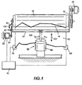
- the electrophotographic printing machine of the present invention uses a charge retentive surface in the form of an Active Matrix (AMAT) photoreceptor belt 10 supported for movement in the direction indicated by arrow 12, for advancing sequentially through the various xerographic process stations.
- the belt 10 is entrained about a utility roller 14 in accordance with the present invention and two rollers 16 and 18.
- Roller 14 is operatively connected to a drive motor 20 for effecting movement of the belt 10 through xerographic stations in the printing machine.
- a portion of photoreceptor belt 10 passes through charging station A where a corona generating device, indicated generally by the reference numeral 22, charges the photoconductive surface of belt 10 to a relative high, substantially uniform, preferably negative potential.
- the charged portion of photoconductive surface is advanced through an exposure or imaging station B.
- the uniformly charged belt 10 is exposed to a laser based output scanning device 24 which causes the charge retentive surface to be discharged in accordance with the output from the scanning device 24.
- the scanning device 24 is a laser Raster Output Scanner (ROS).
- ROS Raster Output Scanner
- the ROS could be replaced by other xerographic exposure devices such as LED arrays.
- the photoreceptor belt 10 which is initially charged to a voltage V 0 , undergoes dark decay to a level V ddp equal to about -500 volts. When exposed at the exposure station B, the photoreceptor belt 10 is discharged to V image equal to about -50 volts. Thus after exposure, the photoreceptor belt 10 contains a monopolar voltage profile of high and low voltages, the former corresponding to charged areas and the latter corresponding to discharged or image areas.
- a magnetic brush developer structure At a first development station C, a magnetic brush developer structure, indicated generally by the reference numeral 26, advances insulative magnetic brush (IMB) material 31 into contact with the electrostatic latent image on the photoreceptor belt 10.
- the development structure 26 comprises a plurality of magnetic brush roller members. These magnetic brush rollers present, for example, charged black toner material to the image areas for development thereof. Appropriate developer biasing is accomplished via power supply 32.
- a corona recharge device 36 having a high output current vs. control surface voltage (I/V) characteristic slope is employed for raising the voltage level of both the toned and untoned areas on the photoreceptor belt 10 to a substantially uniform level.
- the recharging device 36 serves to recharge the photoreceptor belt 10 to a predetermined level.
- a second exposure or imaging device 38 which may comprise a laser based input and/or output structure is utilized for selectively discharging the photoreceptor belt 10 on toned areas and/or bare areas, pursuant to the image to be developed with a second color developer.
- the photoreceptor belt 10 contains toned and untoned areas at relatively high voltage levels, and toned and untoned areas at relatively low voltage levels. These low voltage areas represent image areas which are developed using discharged area development (DAD).
- DAD discharged area development
- a negatively charged, developer material 40 comprising color toner is employed.
- the toner which, by way of example, may be yellow, is contained in a developer housing structure 42 disposed at a second developer station D and is presented to the latent images on the photoreceptor belt 10 by a magnetic brush developer roller.
- a power supply (not shown) serves to electrically bias the developer structure to a level effective to develop the DAD image areas with negatively charged yellow toner particles 40.
- Each of the third and fourth developer stations comprises a housing 42 containing respective developer materials 55, 65, and is located after associated recharge devices 36 and imaging devices 38. In this manner, a full color composite toner image is developed on the photoreceptor belt 10.
- a negative pre-transfer dicorotron member 50 is provided to condition the toner for effective transfer to a substrate using positive corona discharge.
- a sheet of support material 52 is moved into contact with the toner images at transfer station G.
- the sheet of support material 52 is advanced to transfer station G by conventional sheet feeding apparatus, not shown.
- the sheet feeding apparatus includes a feed roll contacting the uppermost sheet of a stack copy sheets. The feed rolls rotate so as to advance the uppermost sheet from stack into a chute which directs the advancing sheet of support material into contact with photoconductive surface of photoreceptor belt 10 in a timed sequence so that the toner powder image developed thereon contacts the advancing sheet of support material 52 at transfer station G.
- Transfer station G includes a transfer dicorotron 54 which sprays positive ions onto the backside of sheet 52. This attracts the negatively charged toner powder images from the belt 10 to sheet 52.
- a detack dicorotron 56 is provided for facilitating stripping of the sheets from the belt 10.
- Fusing station H includes a fuser assembly, indicated generally by the reference numeral 60, which permanently affixes the transferred powder image to sheet 52.
- fuser assembly 60 comprises a heated fuser roller 62 and a backup or pressure roller 64.
- Sheet 52 passes between fuser roller 62 and backup roller 64 with the toner powder image contacting fuser roller 62. In this manner, the toner powder images are permanently affixed to sheet 52 after it is allowed to cool.
- a chute guides the advancing sheets 52 to a catch tray, not shown, for subsequent removal from the printing machine by the operator.
- the residual toner particles carried by the non-image areas on the photoconductive surface of photoreceptor belt 10 are removed therefrom. These particles are removed at cleaning station I using a cleaning brush structure contained in a housing 66.
- the electrophotographic printing machine shown in Figure 3 also includes a controller 90 for controlling the utility roller 14 and the scanning device 24.
- Figure 1 illustrates a plan view of the design of such a utility roller 14.
- the motor 20 and drive transmission 70 are mounted as an integral part at one end of the roller 14. This would usually be mounted at the inboard end thereof which would be toward the rear of the machine (not shown).
- Steering of photoreceptor belt 10 is provided by an outboard yoke mechanism 87.
- the roller 14 is supported by the yoke mechanism 87 which is allowed to pivot about the soft axis, indicated by arrow 120, for steering and to be tensioned along the line indicated by arrow 122 to take up conicity of the photoreceptor belt 10.
- Tensioning of photoreceptor belt 10 is accomplished by the sliding action of the yoke mechanism 87 counterbalanced by a compression spring 88 located within a tensioning slide 86.
- Coulomb friction is left alone in the tensioning slide 86 to function as an energy dissipative mechanism to damp out disturbances from various sources. It can be seen that the driving, steering, and tensioning functions can be combined in one roller as described.
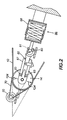
- FIG. 2 illustrates an end view of the utility roller 14 as seen from the outboard portion of the machine.
- the support yoke 87 is illustrated as is the tensioning cylinder 86, which contains the compression spring 88, which is attached to the support yoke 87.
- Arrows 124 represent the line of movement along which the roller 14 tilts to provide steering input.
- the soft axis angle is ideally the bisector of the angle formed by the span of the photoreceptor belt 10 leading into the utility roller 14 and the span of the belt exiting the utility roller 14. However other angles will also accomplish steering of the photoreceptor belt 10.
- a belt edge sensor 92 or plurality of sensors 92, 94 can then be utilized to track the position of the photoreceptor belt 10 and emit a signal indicative of its position to the machine controller 90.
- the controller 90 which is typically a microprocessor can then interpret the position and send actuation signals to steering actuator 80 to control the degree and the duration of tilt necessary to maintain the proper belt track.
- the steering actuator 80 is a rotary stepper motor and cam 81 to obtain precise steering control.
- the cam 81 operates against a steering yoke 82 which is slidably attached to support yoke 87.
- the steering yoke 82 causes the end of utility roller 14 to be deflected up or down along arrows 124 as required to maintain the proper steering control.
- the steering yoke 82 is wedged between bearings 83 to eliminate backlash in the steering mechanism.
- a solenoid or a stepper motor and linkage can also be used to provide accurate steering adjustment.
- a profile of the belt edge can be generated and stored in the controller 90 and the above compact steering mechanism can control the photoreceptor belt 10 with a high degree of accuracy.
- an apparatus for driving, steering and maintaining tension on a moving web particularly in an electrophotographic printing machine of the type having an endless photoreceptor belt supported by a plurality of rollers and arranged to move in a predetermined path through a plurality of processing stations disposed therealong.
- a utility roller 14 is utilised for driving, steering and maintaining tension on the photoreceptor belt and is adapted for rotational movement about a first axis and tilting movement about a second axis transverse to the first axis.
- the drive motor and transmission are mounted integral to the utility roller unit and tilt therewith.
- An actuator tilts the roller in one of two directions to cause the belt to laterally walk therealong to maintain the predetermined belt path.
- a belt edge sensor can be utilized to track the position of the belt and feed that information to the machine controller which then actuates the steering motor to tilt the roller to the extent and for as long as is necessary to maintain the proper belt tracking pattern on the roller.
Claims (6)
- Appareil destiné à commander et à entraíner une bande sans fin (10) qui se déplace selon un chemin prédéterminé, l'appareil comprenant :un rouleau d'alimentation (14) destiné à porter la bande (10), le rouleau d'alimentation (14) étant adapté pour être commandé en rotation autour d'un premier axe et ayant un mouvement d'inclinaison autour d'un deuxième axe perpendiculaire au premier axe ;des moyens d'inclinaison (80, 81, 82, 83, 87) destinés à exécuter le mouvement d'inclinaison ;des moyens de captage (92, 94) destinés au captage du mouvement de la bande (10) dans une direction sensiblement normale au chemin prédéterminé et générant un signal indicatif du mouvement ; etun moyen de commande (90) destiné à maintenir la bande (10) sur le chemin prédéterminé, dans lequel le rouleau d'alimentation (14) est incliné autour du deuxième axe à l'aide des moyens d'inclinaison (80, 81, 82, 83, 87) sous la commande par le moyen de commande (90) en réponse aux signaux générés par les moyens de captage (92, 94) caractérisé en ce que les moyens d'inclinaison (80, 81, 82, 83, 87) comprennent un étrier (87) portant avec possibilité de rotation le rouleau d'alimentation (14) et adapté pour faire tourner le rouleau d'alimentation (14) autour du deuxième axe ; et un actionneur (80, 81, 82, 83) relié à l'étrier et destiné à incliner le rouleau d'alimentation (14).
- Appareil selon la revendication 1, comprenant en outre un dispositif de tension (86, 88) qui agit autour du deuxième axe afin de tendre la bande.
- Appareil selon la revendication 1 ou la revendication 2, dans lequel l'actionneur (80, 81, 82, 83) comprend un moteur pas-à-pas (80) ; et une liaison (81, 82) reliant le moteur pas-à-pas (80) à l'étrier pour déplacer avec précision le rouleau d'alimentation (14) afin de maintenir le rouleau d'alimentation (14) sur le chemin prédéterminé.
- Appareil selon la revendication 3, dans lequel la liaison (81, 82) comprend une came (81) reliée avec possibilité de rotation au moteur pas-à-pas (80) et en contact avec l'étrier (87) pour déplacer le rouleau d'alimentation (14) afin d'exécuter le guidage de la bande.
- Appareil selon l'une quelconque des revendications précédentes, comprenant en outre un moteur (20) monté de manière intégrée avec le rouleau d'alimentation (14) ; et un dispositif de transmission (70) destiné à relier le moteur (20) au rouleau d'alimentation (14) afin de le faire tourner autour du premier axe.
- Imprimante électrophotographique du type comportant une bande de photorécepteur sans fin (10) portée par une pluralité de rouleaux (14, 16, 18) et disposée de manière à la déplacer dans un chemin prédéterminé par l'intermédiaire d'une pluralité de positions d'avancement (A, B, C, D, F, G, H) disposées le long de celui-ci, la machine comprenant un appareil selon l'une quelconque des revendications précédentes.
Applications Claiming Priority (2)
| Application Number | Priority Date | Filing Date | Title |
|---|---|---|---|
| US584764 | 1996-01-11 | ||
| US08/584,764 US5717984A (en) | 1996-01-11 | 1996-01-11 | Driving, steering and tensioning roll for belt loops |
Publications (3)
| Publication Number | Publication Date |
|---|---|
| EP0785480A2 EP0785480A2 (fr) | 1997-07-23 |
| EP0785480A3 EP0785480A3 (fr) | 1999-01-13 |
| EP0785480B1 true EP0785480B1 (fr) | 2003-04-16 |
Family
ID=24338693
Family Applications (1)
| Application Number | Title | Priority Date | Filing Date |
|---|---|---|---|
| EP97300143A Expired - Lifetime EP0785480B1 (fr) | 1996-01-11 | 1997-01-10 | Rouleau d'entraínement de commande et de tension pour les bandes de ruban |
Country Status (4)
| Country | Link |
|---|---|
| US (1) | US5717984A (fr) |
| EP (1) | EP0785480B1 (fr) |
| JP (1) | JPH09197907A (fr) |
| DE (1) | DE69720819T2 (fr) |
Families Citing this family (39)
| Publication number | Priority date | Publication date | Assignee | Title |
|---|---|---|---|---|
| US5978003A (en) * | 1997-06-30 | 1999-11-02 | Imation Corp. | Belt position detection system for belt registration in an electrophotographic imaging system |
| US5896158A (en) * | 1997-06-30 | 1999-04-20 | Imation Corp. | System for registration of a photoconductor belt in an electrophotographic imaging system |
| TW405064B (en) * | 1997-11-29 | 2000-09-11 | Fuji Xerox Co Ltd | Image formation apparatus using endless belt |
| US5895153A (en) * | 1997-12-17 | 1999-04-20 | Eastman Kodak Company | Mechanism for tracking the belt of a belt fuser |
| US5979641A (en) * | 1998-03-19 | 1999-11-09 | Voith Sulzer Paper Technology North America, Inc. | Paper roll guide |
| KR100313871B1 (ko) * | 1998-12-07 | 2002-04-17 | 윤종용 | 인쇄기의 감광 벨트 장력 조절장치_ |
| US6101353A (en) * | 1998-12-21 | 2000-08-08 | Xerox Corporation | Flexible photoreceptor belt detensioning for charge transport layer cracking life extension |
| US6137974A (en) * | 1998-12-21 | 2000-10-24 | Xerox Corporation | Photoreceptor belt tensioner system |
| US6134406A (en) * | 1999-03-11 | 2000-10-17 | Minnesota Mining And Manufacturing Company | Belt steering mechanism for use with an electrophotographic imaging system |
| US6137517A (en) * | 1999-04-14 | 2000-10-24 | Xerox Corporation | Image registration adjustment system and method for dynamically compensating for photoreceptor belt skew |
| WO2001011432A1 (fr) | 1999-08-10 | 2001-02-15 | OCé PRINTING SYSTEMS GMBH | Procede et commande pour la regulation de position d'un support d'image en forme de bande dans un appareil electrographique |
| US6267228B1 (en) * | 1999-08-31 | 2001-07-31 | Lawrence O. Cadwell | Conveyor belt tracking and tensioning system |
| US6321052B1 (en) * | 1999-09-08 | 2001-11-20 | Fuji Xerox Co., Ltd. | Method and apparatus for correcting running state and tension for an endless belt in an image-forming apparatus |
| US6055398A (en) * | 1999-10-19 | 2000-04-25 | Xerox Corporation | Belt tensioner apparatus |
| US6195518B1 (en) * | 1999-11-19 | 2001-02-27 | Charles John Bennett | Web cross-track force monitoring mechanism |
| GB0002617D0 (en) * | 2000-02-05 | 2000-03-29 | Xeikon Nv | Device for steering and tensioning a web |
| EP1139200A3 (fr) | 2000-03-23 | 2002-10-16 | Tradecard Inc. | Système de génération de code d'accès incorporant une carte à puce et un lecteur de cartes à puce |
| US6418286B1 (en) * | 2000-11-06 | 2002-07-09 | Xerox Corporation | Electrostatographic reproduction machine having a belt conicity reducing assembly |
| NL1017538C2 (nl) * | 2001-03-08 | 2002-09-10 | Marius Oskam | Stelsel voor het verzamelen van land- of tuinbouwproducten, in het bijzonder fruit. |
| EP1377510A2 (fr) * | 2001-04-12 | 2004-01-07 | H.B. Fuller Licensing & Financing, Inc. | Procede et systeme permettant de positionner des bras de guidage dans un ensemble de fabrication de bandes |
| DE10147684A1 (de) * | 2001-09-27 | 2003-04-24 | Oce Printing Systems Gmbh | Verfahren zum Ausgleich eines Getriebespiels bei Reversierbetrieb und Vorrichtung zur Durchführung dieses Verfahrens |
| US6567633B2 (en) * | 2001-09-28 | 2003-05-20 | Lexmark International, Inc. | Method and apparatus for reducing lateral motion of a transfer belt of a laser printer |
| US6560428B2 (en) * | 2001-10-10 | 2003-05-06 | Xerox Corporation | Tensioning and detensioning assembly |
| US20040045074A1 (en) * | 2001-12-10 | 2004-03-11 | Vincent Tremblay | Sport catching glove |
| JP4366162B2 (ja) * | 2003-09-19 | 2009-11-18 | キヤノン株式会社 | 画像形成装置 |
| JP3910173B2 (ja) * | 2003-12-26 | 2007-04-25 | 株式会社沖データ | ベルトユニット及び画像形成装置 |
| US7155144B2 (en) * | 2004-07-30 | 2006-12-26 | Xerox Corporation | Photoreceptor belt tensioner providing low variation in belt tension as a function of belt length |
| JP4396559B2 (ja) * | 2005-03-24 | 2010-01-13 | 富士ゼロックス株式会社 | 液滴吐出装置 |
| JP4413854B2 (ja) | 2005-11-29 | 2010-02-10 | 株式会社東芝 | 画像形成装置 |
| JP5090825B2 (ja) * | 2007-08-29 | 2012-12-05 | 株式会社リコー | ベルト装置及び画像形成装置 |
| US7815039B2 (en) * | 2007-12-05 | 2010-10-19 | Seiko Epson Corporation | Belt skew correction device, belt transportation device, and recording device |
| JP5312121B2 (ja) * | 2009-03-19 | 2013-10-09 | キヤノン株式会社 | 画像形成装置 |
| JP2011158493A (ja) * | 2010-01-29 | 2011-08-18 | Konica Minolta Business Technologies Inc | 定着装置及び画像形成装置 |
| US20150291366A1 (en) * | 2012-11-08 | 2015-10-15 | John Pear Cumberlege | Idler |
| US9145262B2 (en) * | 2014-02-20 | 2015-09-29 | Mettler-Toledo, LLC | Conveyor belt tracking mechanism and conveyor employing the same |
| EP2987754B1 (fr) * | 2014-06-04 | 2017-09-20 | Roland DG Corporation | Dispositif de support et imprimante à jet d'encre le comportant |
| EP3196036B1 (fr) * | 2016-01-25 | 2018-11-21 | OCE Holding B.V. | Procédé de commande d'une position latérale d'une courroie sans fin d'un système de transporteur à courroie |
| CN213864109U (zh) * | 2017-10-31 | 2021-08-03 | 易乔工程有限公司 | 一种传送器带对准装置 |
| AU2020356726B2 (en) * | 2019-09-23 | 2023-05-18 | Joshua Pritchard | Conveyor belt tracking apparatus and system |
Family Cites Families (11)
| Publication number | Priority date | Publication date | Assignee | Title |
|---|---|---|---|---|
| US4061222A (en) * | 1975-07-09 | 1977-12-06 | Eastman Kodak Company | Web tracking apparatus |
| US4170175A (en) * | 1978-03-24 | 1979-10-09 | General Electric Company | Belt tracking system |
| US4174171A (en) * | 1978-07-24 | 1979-11-13 | Xerox Corporation | Belt tracking system |
| US4344693A (en) * | 1980-04-14 | 1982-08-17 | Xerox Corporation | Belt tracking system |
| US4572417A (en) * | 1984-04-06 | 1986-02-25 | Eastman Kodak Company | Web tracking apparatus |
| US4557372A (en) * | 1984-08-13 | 1985-12-10 | The Mead Corporation | Belt system with alignment apparatus |
| DE3432549A1 (de) * | 1984-09-05 | 1986-03-13 | G. Siempelkamp Gmbh & Co, 4150 Krefeld | Kontinuierlich arbeitende presse zum verpressen von spanplattenbahnen, faserplattenbahnen u.dgl. pressgutbahnen |
| GB2206308B (en) * | 1987-06-26 | 1991-11-27 | Xerox Corp | Web-steering mechanisms |
| US4961089A (en) * | 1988-12-27 | 1990-10-02 | Eastman Kodak Company | Method and apparatus for web tracking with predictive control |
| US5467171A (en) * | 1993-09-17 | 1995-11-14 | Xerox Corporation | Compact active steering roll for belt loops |
| US5515139A (en) * | 1994-08-29 | 1996-05-07 | Xerox Corporation | Apparatus and method for lateral belt control with backlash compensation |
-
1996
- 1996-01-11 US US08/584,764 patent/US5717984A/en not_active Expired - Lifetime
-
1997
- 1997-01-06 JP JP9000137A patent/JPH09197907A/ja not_active Withdrawn
- 1997-01-10 EP EP97300143A patent/EP0785480B1/fr not_active Expired - Lifetime
- 1997-01-10 DE DE69720819T patent/DE69720819T2/de not_active Expired - Fee Related
Also Published As
| Publication number | Publication date |
|---|---|
| JPH09197907A (ja) | 1997-07-31 |
| DE69720819D1 (de) | 2003-05-22 |
| EP0785480A2 (fr) | 1997-07-23 |
| US5717984A (en) | 1998-02-10 |
| EP0785480A3 (fr) | 1999-01-13 |
| DE69720819T2 (de) | 2003-12-04 |
Similar Documents
| Publication | Publication Date | Title |
|---|---|---|
| EP0785480B1 (fr) | Rouleau d'entraínement de commande et de tension pour les bandes de ruban | |
| US5515139A (en) | Apparatus and method for lateral belt control with backlash compensation | |
| EP0023755B1 (fr) | Dispositif pour régler l'alignement latéral d'une bande | |
| EP0608124B1 (fr) | Procédé et appareil pour déterminer et mettre à jour le coefficient de déviation d'une courroie photoréceptrice | |
| CA1139359A (fr) | Dispositif de guidage de courroie | |
| US6137974A (en) | Photoreceptor belt tensioner system | |
| US5850589A (en) | Sheet moisture replacement system using water jet technology | |
| US5923921A (en) | Variable transfer assist blade force | |
| EP0905574B1 (fr) | Contrôle de l'humidification du papier pour éviter son gondolement | |
| US5467171A (en) | Compact active steering roll for belt loops | |
| US5383006A (en) | Compliant edge guide belt loops | |
| EP1293845B1 (fr) | Lame composite d'aide pour le transfert complet d' une image de révélateur d'une surface photosensible | |
| US5559587A (en) | Image forming apparatus | |
| US5937258A (en) | Paper conditioner with articulating back-up/transfer rollers | |
| EP0622706B1 (fr) | Système de transfert ayant une lame segmentée, flexible et actionnée par came pour aider au transfert | |
| US5387962A (en) | Self-aligning roll for belt loop modules | |
| US9116487B2 (en) | Image forming apparatus | |
| US6460846B2 (en) | Reproduction machine having a safe tiltable paper tray | |
| US5337133A (en) | System to extend fuser roll life | |
| JP4244594B2 (ja) | ベルト搬送装置及びこれを用いた画像形成装置 | |
| EP0617341B1 (fr) | Séparation de papier des bandes de photorécepteurs avec contrainte réduite | |
| US6636714B1 (en) | Roll having relieved edges for low stress belt tracking for belt loops | |
| US6055398A (en) | Belt tensioner apparatus | |
| US5745142A (en) | Apparatus for positioning a linear printhead in an accurate position with respect to a belt or web member | |
| JP2001125390A (ja) | 画像形成装置 |
Legal Events
| Date | Code | Title | Description |
|---|---|---|---|
| PUAI | Public reference made under article 153(3) epc to a published international application that has entered the european phase |
Free format text: ORIGINAL CODE: 0009012 |
|
| AK | Designated contracting states |
Kind code of ref document: A2 Designated state(s): DE FR GB |
|
| PUAL | Search report despatched |
Free format text: ORIGINAL CODE: 0009013 |
|
| AK | Designated contracting states |
Kind code of ref document: A3 Designated state(s): DE FR GB |
|
| 17P | Request for examination filed |
Effective date: 19990713 |
|
| 17Q | First examination report despatched |
Effective date: 20011217 |
|
| GRAG | Despatch of communication of intention to grant |
Free format text: ORIGINAL CODE: EPIDOS AGRA |
|
| GRAG | Despatch of communication of intention to grant |
Free format text: ORIGINAL CODE: EPIDOS AGRA |
|
| GRAH | Despatch of communication of intention to grant a patent |
Free format text: ORIGINAL CODE: EPIDOS IGRA |
|
| GRAH | Despatch of communication of intention to grant a patent |
Free format text: ORIGINAL CODE: EPIDOS IGRA |
|
| GRAA | (expected) grant |
Free format text: ORIGINAL CODE: 0009210 |
|
| AK | Designated contracting states |
Designated state(s): DE FR GB |
|
| REG | Reference to a national code |
Ref country code: GB Ref legal event code: FG4D |
|
| REF | Corresponds to: |
Ref document number: 69720819 Country of ref document: DE Date of ref document: 20030522 Kind code of ref document: P |
|
| ET | Fr: translation filed | ||
| PLBE | No opposition filed within time limit |
Free format text: ORIGINAL CODE: 0009261 |
|
| STAA | Information on the status of an ep patent application or granted ep patent |
Free format text: STATUS: NO OPPOSITION FILED WITHIN TIME LIMIT |
|
| 26N | No opposition filed |
Effective date: 20040119 |
|
| REG | Reference to a national code |
Ref country code: GB Ref legal event code: 746 Effective date: 20041130 |
|
| PGFP | Annual fee paid to national office [announced via postgrant information from national office to epo] |
Ref country code: GB Payment date: 20050105 Year of fee payment: 9 |
|
| PGFP | Annual fee paid to national office [announced via postgrant information from national office to epo] |
Ref country code: DE Payment date: 20050106 Year of fee payment: 9 |
|
| PGFP | Annual fee paid to national office [announced via postgrant information from national office to epo] |
Ref country code: FR Payment date: 20050110 Year of fee payment: 9 |
|
| REG | Reference to a national code |
Ref country code: FR Ref legal event code: D6 |
|
| PG25 | Lapsed in a contracting state [announced via postgrant information from national office to epo] |
Ref country code: GB Free format text: LAPSE BECAUSE OF NON-PAYMENT OF DUE FEES Effective date: 20060110 |
|
| PG25 | Lapsed in a contracting state [announced via postgrant information from national office to epo] |
Ref country code: FR Free format text: LAPSE BECAUSE OF NON-PAYMENT OF DUE FEES Effective date: 20060131 |
|
| PG25 | Lapsed in a contracting state [announced via postgrant information from national office to epo] |
Ref country code: DE Free format text: LAPSE BECAUSE OF NON-PAYMENT OF DUE FEES Effective date: 20060801 |
|
| GBPC | Gb: european patent ceased through non-payment of renewal fee |
Effective date: 20060110 |
|
| REG | Reference to a national code |
Ref country code: FR Ref legal event code: ST Effective date: 20060929 |