EP0785290A1 - Lateraler Schnellverdampfer - Google Patents
Lateraler Schnellverdampfer Download PDFInfo
- Publication number
- EP0785290A1 EP0785290A1 EP97100496A EP97100496A EP0785290A1 EP 0785290 A1 EP0785290 A1 EP 0785290A1 EP 97100496 A EP97100496 A EP 97100496A EP 97100496 A EP97100496 A EP 97100496A EP 0785290 A1 EP0785290 A1 EP 0785290A1
- Authority
- EP
- European Patent Office
- Prior art keywords
- metal
- cavity
- flash evaporator
- evaporator
- open area
- Prior art date
- Legal status (The legal status is an assumption and is not a legal conclusion. Google has not performed a legal analysis and makes no representation as to the accuracy of the status listed.)
- Granted
Links
- 229910052751 metal Inorganic materials 0.000 claims abstract description 37
- 239000002184 metal Substances 0.000 claims abstract description 37
- 238000001704 evaporation Methods 0.000 claims abstract description 24
- PZNSFCLAULLKQX-UHFFFAOYSA-N Boron nitride Chemical compound N#B PZNSFCLAULLKQX-UHFFFAOYSA-N 0.000 claims abstract description 18
- 239000011248 coating agent Substances 0.000 claims abstract description 16
- 238000000576 coating method Methods 0.000 claims abstract description 16
- OKTJSMMVPCPJKN-UHFFFAOYSA-N Carbon Chemical compound [C] OKTJSMMVPCPJKN-UHFFFAOYSA-N 0.000 claims abstract description 13
- 229910002804 graphite Inorganic materials 0.000 claims abstract description 13
- 239000010439 graphite Substances 0.000 claims abstract description 13
- 230000000295 complement effect Effects 0.000 claims description 4
- 230000008020 evaporation Effects 0.000 description 14
- 229910052782 aluminium Inorganic materials 0.000 description 4
- XAGFODPZIPBFFR-UHFFFAOYSA-N aluminium Chemical compound [Al] XAGFODPZIPBFFR-UHFFFAOYSA-N 0.000 description 4
- 239000000919 ceramic Substances 0.000 description 3
- 238000001883 metal evaporation Methods 0.000 description 3
- 238000009834 vaporization Methods 0.000 description 3
- 230000008016 vaporization Effects 0.000 description 3
- QGZKDVFQNNGYKY-UHFFFAOYSA-N Ammonia Chemical compound N QGZKDVFQNNGYKY-UHFFFAOYSA-N 0.000 description 2
- 229910052582 BN Inorganic materials 0.000 description 2
- 238000003754 machining Methods 0.000 description 2
- 230000008018 melting Effects 0.000 description 2
- 238000002844 melting Methods 0.000 description 2
- 150000002739 metals Chemical class 0.000 description 2
- 238000000034 method Methods 0.000 description 2
- 239000000758 substrate Substances 0.000 description 2
- WFKWXMTUELFFGS-UHFFFAOYSA-N tungsten Chemical compound [W] WFKWXMTUELFFGS-UHFFFAOYSA-N 0.000 description 2
- 229910052721 tungsten Inorganic materials 0.000 description 2
- 239000010937 tungsten Substances 0.000 description 2
- QYEXBYZXHDUPRC-UHFFFAOYSA-N B#[Ti]#B Chemical compound B#[Ti]#B QYEXBYZXHDUPRC-UHFFFAOYSA-N 0.000 description 1
- BQCADISMDOOEFD-UHFFFAOYSA-N Silver Chemical compound [Ag] BQCADISMDOOEFD-UHFFFAOYSA-N 0.000 description 1
- 229910033181 TiB2 Inorganic materials 0.000 description 1
- ATJFFYVFTNAWJD-UHFFFAOYSA-N Tin Chemical compound [Sn] ATJFFYVFTNAWJD-UHFFFAOYSA-N 0.000 description 1
- MUBKMWFYVHYZAI-UHFFFAOYSA-N [Al].[Cu].[Zn] Chemical compound [Al].[Cu].[Zn] MUBKMWFYVHYZAI-UHFFFAOYSA-N 0.000 description 1
- 229910021529 ammonia Inorganic materials 0.000 description 1
- 229910052796 boron Inorganic materials 0.000 description 1
- -1 boron halide Chemical class 0.000 description 1
- 239000002131 composite material Substances 0.000 description 1
- 238000010276 construction Methods 0.000 description 1
- PMHQVHHXPFUNSP-UHFFFAOYSA-M copper(1+);methylsulfanylmethane;bromide Chemical compound Br[Cu].CSC PMHQVHHXPFUNSP-UHFFFAOYSA-M 0.000 description 1
- 238000000151 deposition Methods 0.000 description 1
- 238000007599 discharging Methods 0.000 description 1
- 239000006185 dispersion Substances 0.000 description 1
- 239000011521 glass Substances 0.000 description 1
- PCHJSUWPFVWCPO-UHFFFAOYSA-N gold Chemical compound [Au] PCHJSUWPFVWCPO-UHFFFAOYSA-N 0.000 description 1
- 229910052737 gold Inorganic materials 0.000 description 1
- 239000010931 gold Substances 0.000 description 1
- 239000004033 plastic Substances 0.000 description 1
- 229910052709 silver Inorganic materials 0.000 description 1
- 239000004332 silver Substances 0.000 description 1
- 239000007787 solid Substances 0.000 description 1
- 238000002207 thermal evaporation Methods 0.000 description 1
- 239000011135 tin Substances 0.000 description 1
- 229910052718 tin Inorganic materials 0.000 description 1
- 238000009736 wetting Methods 0.000 description 1
Images
Classifications
-
- C—CHEMISTRY; METALLURGY
- C23—COATING METALLIC MATERIAL; COATING MATERIAL WITH METALLIC MATERIAL; CHEMICAL SURFACE TREATMENT; DIFFUSION TREATMENT OF METALLIC MATERIAL; COATING BY VACUUM EVAPORATION, BY SPUTTERING, BY ION IMPLANTATION OR BY CHEMICAL VAPOUR DEPOSITION, IN GENERAL; INHIBITING CORROSION OF METALLIC MATERIAL OR INCRUSTATION IN GENERAL
- C23C—COATING METALLIC MATERIAL; COATING MATERIAL WITH METALLIC MATERIAL; SURFACE TREATMENT OF METALLIC MATERIAL BY DIFFUSION INTO THE SURFACE, BY CHEMICAL CONVERSION OR SUBSTITUTION; COATING BY VACUUM EVAPORATION, BY SPUTTERING, BY ION IMPLANTATION OR BY CHEMICAL VAPOUR DEPOSITION, IN GENERAL
- C23C14/00—Coating by vacuum evaporation, by sputtering or by ion implantation of the coating forming material
- C23C14/22—Coating by vacuum evaporation, by sputtering or by ion implantation of the coating forming material characterised by the process of coating
- C23C14/24—Vacuum evaporation
- C23C14/243—Crucibles for source material
-
- C—CHEMISTRY; METALLURGY
- C23—COATING METALLIC MATERIAL; COATING MATERIAL WITH METALLIC MATERIAL; CHEMICAL SURFACE TREATMENT; DIFFUSION TREATMENT OF METALLIC MATERIAL; COATING BY VACUUM EVAPORATION, BY SPUTTERING, BY ION IMPLANTATION OR BY CHEMICAL VAPOUR DEPOSITION, IN GENERAL; INHIBITING CORROSION OF METALLIC MATERIAL OR INCRUSTATION IN GENERAL
- C23C—COATING METALLIC MATERIAL; COATING MATERIAL WITH METALLIC MATERIAL; SURFACE TREATMENT OF METALLIC MATERIAL BY DIFFUSION INTO THE SURFACE, BY CHEMICAL CONVERSION OR SUBSTITUTION; COATING BY VACUUM EVAPORATION, BY SPUTTERING, BY ION IMPLANTATION OR BY CHEMICAL VAPOUR DEPOSITION, IN GENERAL
- C23C14/00—Coating by vacuum evaporation, by sputtering or by ion implantation of the coating forming material
- C23C14/22—Coating by vacuum evaporation, by sputtering or by ion implantation of the coating forming material characterised by the process of coating
- C23C14/24—Vacuum evaporation
- C23C14/26—Vacuum evaporation by resistance or inductive heating of the source
Definitions
- This invention relates to an improved resistance heated flash evaporator for the vaporization of metals and more particularly to a flash evaporator for metal evaporation in a substantially lateral direction.
- Thermal evaporation is a common method for coating metals such as aluminum, copper, zinc, tin, silver and gold onto various substrates of metal, glass and plastic.
- the metal coating may be formed from a flash or semi-continuous evaporation of metal using a resistance heater composed of a ceramic or metal vessel commonly referred to as a "boat" or from a wire filament.
- a ceramic or metal boat serves as the electrical resistance heater a cavity is formed in the boat to function as a receptacle for the metal charge which may be inserted into the cavity prior to each evaporation cycle or fed into the cavity.
- the boat is connected to a source of electrical power and is heated to a temperature which will cause the metal charge in contact with the boat to melt and vaporize.
- the metal charge wets the cavity after melting and during evaporation causing metal evaporant to disperse from the boat in a direction substantially transverse to the cavity surface. Accordingly, if the boat is aligned in a horizontal direction during evaporation of the metal charge the metal evaporant will necessarily disperse upwardly from the cavity.
- a metal wire filament serves as the resistance heater for substantially all such applications.
- the metal wire filament is typically composed of tungsten and has a useful life of from 2 to 35 flashes when used to evaporate aluminum. In such case the circuit resistance of the wire filament changes dramatically during each flash cycle as a result of melting of the aluminum and wetting of the wire filament.
- aluminum which is often the preferred metal evaporant, will chemically attack a wire filament of tungsten thereby causing electrical resistance variations and substantially limiting its useful life.
- a modified vessel or "boat” has been discovered in accordance with the present invention for use as a resistance heater to provide flash or semi-continuous evaporation of metal in a substantially lateral direction without incurring any of the disadvantages from the use of a wire filament resistance heater.
- the flash evaporator of the present invention comprises: a body having two opposite open sides and a cavity extending from each of said two opposite open sides for forming a continuous open area between said opposite sides and with said body having at least one metal evaporating surface formed by said cavity facing said open area for evaporating metal into said open area and laterally through the opposite sides of the body.
- a resistance heated flash evaporator for the vaporization of metal may be composed of an intermetallic ceramic composite of titanium diboride and boron nitride alone or in combination with aluminum nitride.
- the resistance heated flash evaporator may be composed of a graphite body having a coating of pyrolytic boron nitride ("PBN").
- PBN coated graphite evaporator is known to possess a longer useful life and is accordingly preferred for purposes of the present invention.
- a typical PBN coated graphite evaporator is taught in US Patent No's 4,264,803 and 5,239,612; the disclosure of each incorporated herein by reference.
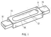
- the prior art pyrolytic boron nitride coated graphite evaporator as taught in the aforementioned patents is shown in Figure 1.
- the body 11 of the evaporator 10 is preferably formed from a graphite block with a long and narrow geometry having a cavity or depression 12 machined therein from at least one surface 14.
- a thin layer of pyrolytic boron nitride 18 is coated over the body 11 of the evaporator 10.
- the process for forming a pyrolytic coating of boron nitride is also conventional and briefly involves introducing vapors of ammonia and a gaseous boron halide in a suitable ratio into a heated furnace reactor containing the graphite body 11 with the furnace maintained at a controlled temperature of between 1600°C to 2200°C as explained in US Patent No. 3, 182, 006 the disclosure of which is herein incorporated by reference.
- the coating 18 of pyrolytic boron nitride is usually no thicker than 0.030 inches and fully encapsulates the graphite body 11 except at the ends 15 and 16 which are exposed for purposes of making an electrical connection through a clamp assembly (not shown) to an external source of power (not shown).
- the pyrolytic coating 18 may be removed from the ends 15 and 16 of the body 11 by a machining operation or the ends 15 and 16 may be masked during the coating operation to prevent coating of the ends 15 and 16.
- the body 11 of the resistance heater 10 is preferably of a rectangular configuration having a predetermined cross sectional area to provide a defined resistance path which will optimize the heat generated therein for a given applied voltage to assure complete evaporation of the metal charge under controlled heat cycle conditions. It has been discovered in accordance with the present invention that a desirable resistance path may be established in a resistance heater of any desired geometry, to permit metal evaporation in substantially lateral directions through opposite sides of the heater as will be explained hereafter in detail in connection with Figures 2 and 3 inclusive.
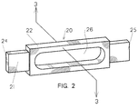
- the resistance heated evaporator vessel 20 of the present invention as is shown in Figures 2 and 3 is preferably formed from a graphite body 21 having a desired geometry such as a rectangular or cylindrical solid with a coating 22 of pyrolytic boron nitride (PBN) although it is not limited to a PBN coated graphite construction.
- PBN pyrolytic boron nitride
- a PBN coated evaporator has a useful life of from 500 to 3500 flashes which is two orders of magnitude over that of a wire filament.
- the ends 24 and 25 of the graphite body 21 are left exposed or the coating 22 is machined to expose the ends 24 and 25 in order to facilitate attachment to a power supply (not shown) as taught in the above mentioned Patent No's 4,264, 803 and 5, 239,612 respectively.
- a hollow cavity 26 is formed or machined into the body 21 to provide a continuous open area 29 extending between two opposite sides 27 and 28 of the body 21.
- the PBN coating is formed after forming the cavity 26 so that the PBN coating coats the surfaces of the cavity 26 facing the open area 29.
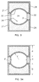
- FIG. 3 A cross section of the body 21 taken along the lines 3-3 is shown in Figure 3.
- the hollow cavity 26 forms two complementary surfaces 30 and 31 facing the open area on opposite sides of the cavity 26. Either of the two surfaces, preferably both, may be used in accordance with the present invention as the evaporation surface for the evaporation of metal.
- the metal to be evaporated is placed upon or fed into contact with the evaporation surfaces 30 and 31 and evaporated simultaneously into the open area 29 with the evaporant discharging through the opposite open sides 27 and 28.
- the vessel 20 is vertically or horizontally oriented the evaporation of metal from the vessel 20 will occur laterally in two directions from the open sides 27 and 28.
- the complementary surfaces 30 and 31 may be of any geometry including a flat or curved surface.
- a surface having a concavity 32 is preferred.
- a depression of concave geometry may be formed in either or both surfaces 30 and 31 by machining a groove into the surface(s).
- the concavity 32 functions as a reservoir for the placement of metal before the start of each flash evaporation cycle equivalent to the depression 12 in the prior art vessel of Figure 1.
- the area of the concavity 32 as determined from its radius of curvature "r” will control the amount of metal that can be evaporated in a single flash whereas the dimensions "a", "b", “c” and “d” of the vessel 20 as shown in Figure 3 determines the area of irradiation of the metal evaporant and the defined resistance path to optimize the heat generated in the evaporator vessel 20.
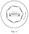
- FIG. 4 One arrangement of product in accordance with the present invention is illustrated in Figure 4 showing the resistance heated evaporator vessel 20 in the symmetrical center of a rotable cylinder inside the vacuum chamber 30 with product 32 such as laser disks mounted inside the cylinder for rotation with the chamber 30.
- product 32 such as laser disks mounted inside the cylinder for rotation with the chamber 30.
- the laser disks 32 are arranged symmetrically inside the vessel 20 for rotation on a rotable drum e.g. in a counterclockwise direction as shown by the arrow A1. This results in the metal evaporant depositing symmetrically over the entire surface of each product 32.
Landscapes
- Chemical & Material Sciences (AREA)
- Chemical Kinetics & Catalysis (AREA)
- Engineering & Computer Science (AREA)
- Materials Engineering (AREA)
- Mechanical Engineering (AREA)
- Metallurgy (AREA)
- Organic Chemistry (AREA)
- Physical Vapour Deposition (AREA)
Applications Claiming Priority (2)
| Application Number | Priority Date | Filing Date | Title |
|---|---|---|---|
| US586326 | 1975-06-12 | ||
| US08/586,326 US5671322A (en) | 1996-01-17 | 1996-01-17 | Lateral flash evaporator |
Publications (2)
| Publication Number | Publication Date |
|---|---|
| EP0785290A1 true EP0785290A1 (de) | 1997-07-23 |
| EP0785290B1 EP0785290B1 (de) | 1999-04-07 |
Family
ID=24345283
Family Applications (1)
| Application Number | Title | Priority Date | Filing Date |
|---|---|---|---|
| EP97100496A Expired - Lifetime EP0785290B1 (de) | 1996-01-17 | 1997-01-15 | Lateraler Schnellverdampfer |
Country Status (6)
| Country | Link |
|---|---|
| US (1) | US5671322A (de) |
| EP (1) | EP0785290B1 (de) |
| JP (1) | JPH111765A (de) |
| KR (1) | KR100315982B1 (de) |
| DE (1) | DE69700167T2 (de) |
| TW (1) | TW464151U (de) |
Cited By (1)
| Publication number | Priority date | Publication date | Assignee | Title |
|---|---|---|---|---|
| EP1479905A2 (de) * | 2003-05-13 | 2004-11-24 | C.R.F. Società Consortile per Azioni | Formgedächtnis-Dünnschichtaktor und dessen Herstellungsverfahren |
Families Citing this family (6)
| Publication number | Priority date | Publication date | Assignee | Title |
|---|---|---|---|---|
| DE19735814A1 (de) * | 1997-08-18 | 1999-02-25 | Kempten Elektroschmelz Gmbh | Keramische Flash-TV-Verdampfer |
| US8080127B2 (en) * | 2007-04-15 | 2011-12-20 | Graftech International Holdings Inc. | Carbon foam evaporator |
| US20120101592A1 (en) * | 2010-09-29 | 2012-04-26 | Zimmer, Inc. | Pyrolytic Carbon Implants With Porous Fixation Component And Methods Of Making The Same |
| EP2755921B1 (de) | 2011-09-14 | 2020-02-05 | Aquasource Technologies Corporation | System und verfahren zur wasseraufbereitung |
| US20160046408A1 (en) * | 2015-10-27 | 2016-02-18 | L'Air Liquide, Société Anonyme pour l'Etude et l'Exploitation des Procédés Georges Claude | Internally coated vessel for housing a metal halide |
| DE102019110950A1 (de) | 2019-04-29 | 2020-10-29 | Kennametal Inc. | Hartmetallzusammensetzungen und deren Anwendungen |
Citations (3)
| Publication number | Priority date | Publication date | Assignee | Title |
|---|---|---|---|---|
| US3024761A (en) * | 1958-07-01 | 1962-03-13 | Ibm | Vacuum evaporation apparatus |
| US4264893A (en) | 1974-01-25 | 1981-04-28 | Honeywell Inc. | Data communication system |
| US5239612A (en) | 1991-12-20 | 1993-08-24 | Praxair S.T. Technology, Inc. | Method for resistance heating of metal using a pyrolytic boron nitride coated graphite boat |
Family Cites Families (7)
| Publication number | Priority date | Publication date | Assignee | Title |
|---|---|---|---|---|
| US3746502A (en) * | 1971-12-20 | 1973-07-17 | Xerox Corp | Evaporation crucible |
| US3748090A (en) * | 1971-12-20 | 1973-07-24 | Xerox Corp | Evaporation crucible |
| US4264803A (en) * | 1978-01-10 | 1981-04-28 | Union Carbide Corporation | Resistance-heated pyrolytic boron nitride coated graphite boat for metal vaporization |
| US4773852A (en) * | 1985-06-11 | 1988-09-27 | Denki Kagaku Kogyo Kabushiki Kaisha | Pyrolytic boron nitride crucible and method for producing the same |
| US5158750A (en) * | 1990-06-06 | 1992-10-27 | Praxair S.T. Technology, Inc. | Boron nitride crucible |
| US5167984A (en) * | 1990-12-06 | 1992-12-01 | Xerox Corporation | Vacuum deposition process |
| US5395180A (en) * | 1993-12-14 | 1995-03-07 | Advanced Ceramics Corporation | Boron nitride vaporization vessel |
-
1996
- 1996-01-17 US US08/586,326 patent/US5671322A/en not_active Expired - Fee Related
-
1997
- 1997-01-15 DE DE69700167T patent/DE69700167T2/de not_active Expired - Fee Related
- 1997-01-15 TW TW087203892U patent/TW464151U/zh not_active IP Right Cessation
- 1997-01-15 EP EP97100496A patent/EP0785290B1/de not_active Expired - Lifetime
- 1997-01-16 KR KR1019970001121A patent/KR100315982B1/ko not_active Expired - Fee Related
- 1997-01-17 JP JP9006851A patent/JPH111765A/ja active Pending
Patent Citations (3)
| Publication number | Priority date | Publication date | Assignee | Title |
|---|---|---|---|---|
| US3024761A (en) * | 1958-07-01 | 1962-03-13 | Ibm | Vacuum evaporation apparatus |
| US4264893A (en) | 1974-01-25 | 1981-04-28 | Honeywell Inc. | Data communication system |
| US5239612A (en) | 1991-12-20 | 1993-08-24 | Praxair S.T. Technology, Inc. | Method for resistance heating of metal using a pyrolytic boron nitride coated graphite boat |
Non-Patent Citations (2)
| Title |
|---|
| J.L.OREHOTSKY ET AL.: "Silver evaporation boat", IBM TECHNICAL DISCLOSURE BULLETIN, vol. 13, no. 5, October 1970 (1970-10-01), pages 1061, XP002029920 * |
| WYTENBURG W J ET AL: "LONG-LIVED ALUMINIUM EVAPORATION SOURCE FOR CONTROLLED, REPRODUCIBLE DEPOSITION OF CLEAN ULTRATHIN FILMS UNDER ULTRAHIGH VACUUM CONDITIONS", JOURNAL OF VACUUM SCIENCE AND TECHNOLOGY: PART A, vol. 10, no. 6, 1 November 1992 (1992-11-01), pages 3597 - 3598, XP000322761 * |
Cited By (1)
| Publication number | Priority date | Publication date | Assignee | Title |
|---|---|---|---|---|
| EP1479905A2 (de) * | 2003-05-13 | 2004-11-24 | C.R.F. Società Consortile per Azioni | Formgedächtnis-Dünnschichtaktor und dessen Herstellungsverfahren |
Also Published As
| Publication number | Publication date |
|---|---|
| JPH111765A (ja) | 1999-01-06 |
| EP0785290B1 (de) | 1999-04-07 |
| DE69700167T2 (de) | 1999-07-29 |
| TW464151U (en) | 2001-11-11 |
| KR100315982B1 (ko) | 2002-02-19 |
| US5671322A (en) | 1997-09-23 |
| KR970059306A (ko) | 1997-08-12 |
| DE69700167D1 (de) | 1999-05-12 |
Similar Documents
| Publication | Publication Date | Title |
|---|---|---|
| US4264803A (en) | Resistance-heated pyrolytic boron nitride coated graphite boat for metal vaporization | |
| US5239612A (en) | Method for resistance heating of metal using a pyrolytic boron nitride coated graphite boat | |
| CA1203373A (en) | Resistance-heated boat for metal vaporization | |
| US20090217876A1 (en) | Coating System For A Ceramic Evaporator Boat | |
| SE458205B (sv) | Foerfarande och anordning foer belaeggning av ett substrat med material, som paa elektrisk vaeg har oeverfoerts till aangfas | |
| US5671322A (en) | Lateral flash evaporator | |
| CA1193494A (en) | Method of and apparatus for the vapor deposition of material upon a substrate | |
| US6404982B1 (en) | High density flash evaporator | |
| US5495550A (en) | Graphite flash evaporator having at least one intermediate layer and a pyrolytic boron nitride coating | |
| US6645572B2 (en) | Process for producing a ceramic evaporation boat having an improved initial wetting performance | |
| US5395180A (en) | Boron nitride vaporization vessel | |
| US4701769A (en) | Thermal head and method for fabrication thereof | |
| US3430937A (en) | Evaporant holder | |
| CA1264613A (en) | Process and apparatus for metallising foils in a vacuum roll coating machine | |
| US5493630A (en) | Pyrolytic boron nitride coated flash evaporator | |
| CA2271933C (en) | Ceramic evaporation boats having improved initial wetting performance and properties | |
| KR100442553B1 (ko) | 순간증발기 용기 | |
| KR0177836B1 (ko) | 열분해성 질화붕소 피복제로 피복처리된 흑연도가니로를 사용해서 금속을 저항가열하는 방법 | |
| JPH083748A (ja) | 蒸着用坩堝およびその製造方法 | |
| HK1014036B (en) | Method for evaporating metal using a resistance heated, pyrolytic boron nitrided coated graphite boat | |
| JPS6033559Y2 (ja) | 電子銃 | |
| JP2003096558A (ja) | 蒸着ボート | |
| JPS5815492Y2 (ja) | アルミニウム蒸発用ルツボ | |
| KR0116791Y1 (ko) | 저항가열식 진공증착용 증발기 | |
| JPH0275888A (ja) | 金属溶解用るつぼ |
Legal Events
| Date | Code | Title | Description |
|---|---|---|---|
| PUAI | Public reference made under article 153(3) epc to a published international application that has entered the european phase |
Free format text: ORIGINAL CODE: 0009012 |
|
| AK | Designated contracting states |
Kind code of ref document: A1 Designated state(s): DE FR GB NL |
|
| 17P | Request for examination filed |
Effective date: 19980119 |
|
| 17Q | First examination report despatched |
Effective date: 19980225 |
|
| GRAG | Despatch of communication of intention to grant |
Free format text: ORIGINAL CODE: EPIDOS AGRA |
|
| GRAG | Despatch of communication of intention to grant |
Free format text: ORIGINAL CODE: EPIDOS AGRA |
|
| GRAH | Despatch of communication of intention to grant a patent |
Free format text: ORIGINAL CODE: EPIDOS IGRA |
|
| GRAH | Despatch of communication of intention to grant a patent |
Free format text: ORIGINAL CODE: EPIDOS IGRA |
|
| GRAA | (expected) grant |
Free format text: ORIGINAL CODE: 0009210 |
|
| AK | Designated contracting states |
Kind code of ref document: B1 Designated state(s): DE FR GB NL |
|
| REF | Corresponds to: |
Ref document number: 69700167 Country of ref document: DE Date of ref document: 19990512 |
|
| ET | Fr: translation filed | ||
| PLBE | No opposition filed within time limit |
Free format text: ORIGINAL CODE: 0009261 |
|
| STAA | Information on the status of an ep patent application or granted ep patent |
Free format text: STATUS: NO OPPOSITION FILED WITHIN TIME LIMIT |
|
| 26N | No opposition filed | ||
| PGFP | Annual fee paid to national office [announced via postgrant information from national office to epo] |
Ref country code: FR Payment date: 20011219 Year of fee payment: 6 |
|
| PGFP | Annual fee paid to national office [announced via postgrant information from national office to epo] |
Ref country code: DE Payment date: 20011220 Year of fee payment: 6 |
|
| PGFP | Annual fee paid to national office [announced via postgrant information from national office to epo] |
Ref country code: GB Payment date: 20011221 Year of fee payment: 6 |
|
| REG | Reference to a national code |
Ref country code: GB Ref legal event code: IF02 |
|
| PGFP | Annual fee paid to national office [announced via postgrant information from national office to epo] |
Ref country code: NL Payment date: 20020107 Year of fee payment: 6 |
|
| PG25 | Lapsed in a contracting state [announced via postgrant information from national office to epo] |
Ref country code: GB Free format text: LAPSE BECAUSE OF NON-PAYMENT OF DUE FEES Effective date: 20030115 |
|
| PG25 | Lapsed in a contracting state [announced via postgrant information from national office to epo] |
Ref country code: NL Free format text: LAPSE BECAUSE OF NON-PAYMENT OF DUE FEES Effective date: 20030801 Ref country code: DE Free format text: LAPSE BECAUSE OF NON-PAYMENT OF DUE FEES Effective date: 20030801 |
|
| GBPC | Gb: european patent ceased through non-payment of renewal fee | ||
| PG25 | Lapsed in a contracting state [announced via postgrant information from national office to epo] |
Ref country code: FR Free format text: LAPSE BECAUSE OF NON-PAYMENT OF DUE FEES Effective date: 20030930 |
|
| NLV4 | Nl: lapsed or anulled due to non-payment of the annual fee |
Effective date: 20030801 |
|
| REG | Reference to a national code |
Ref country code: FR Ref legal event code: ST |