EP0784518B2 - Microbiological parts washer - Google Patents
Microbiological parts washer Download PDFInfo
- Publication number
- EP0784518B2 EP0784518B2 EP19950936304 EP95936304A EP0784518B2 EP 0784518 B2 EP0784518 B2 EP 0784518B2 EP 19950936304 EP19950936304 EP 19950936304 EP 95936304 A EP95936304 A EP 95936304A EP 0784518 B2 EP0784518 B2 EP 0784518B2
- Authority
- EP
- European Patent Office
- Prior art keywords
- chamber
- fluid
- parts
- washing
- microorganisms
- Prior art date
- Legal status (The legal status is an assumption and is not a legal conclusion. Google has not performed a legal analysis and makes no representation as to the accuracy of the status listed.)
- Expired - Lifetime
Links
Images


Classifications
-
- C—CHEMISTRY; METALLURGY
- C02—TREATMENT OF WATER, WASTE WATER, SEWAGE, OR SLUDGE
- C02F—TREATMENT OF WATER, WASTE WATER, SEWAGE, OR SLUDGE
- C02F3/00—Biological treatment of water, waste water, or sewage
- C02F3/34—Biological treatment of water, waste water, or sewage characterised by the microorganisms used
- C02F3/344—Biological treatment of water, waste water, or sewage characterised by the microorganisms used for digestion of mineral oil
-
- B—PERFORMING OPERATIONS; TRANSPORTING
- B08—CLEANING
- B08B—CLEANING IN GENERAL; PREVENTION OF FOULING IN GENERAL
- B08B3/00—Cleaning by methods involving the use or presence of liquid or steam
- B08B3/02—Cleaning by the force of jets or sprays
-
- B—PERFORMING OPERATIONS; TRANSPORTING
- B08—CLEANING
- B08B—CLEANING IN GENERAL; PREVENTION OF FOULING IN GENERAL
- B08B3/00—Cleaning by methods involving the use or presence of liquid or steam
- B08B3/006—Cabinets or cupboards specially adapted for cleaning articles by hand
-
- B—PERFORMING OPERATIONS; TRANSPORTING
- B08—CLEANING
- B08B—CLEANING IN GENERAL; PREVENTION OF FOULING IN GENERAL
- B08B7/00—Cleaning by methods not provided for in a single other subclass or a single group in this subclass
-
- C—CHEMISTRY; METALLURGY
- C02—TREATMENT OF WATER, WASTE WATER, SEWAGE, OR SLUDGE
- C02F—TREATMENT OF WATER, WASTE WATER, SEWAGE, OR SLUDGE
- C02F3/00—Biological treatment of water, waste water, or sewage
- C02F3/02—Aerobic processes
- C02F3/04—Aerobic processes using trickle filters
-
- C—CHEMISTRY; METALLURGY
- C02—TREATMENT OF WATER, WASTE WATER, SEWAGE, OR SLUDGE
- C02F—TREATMENT OF WATER, WASTE WATER, SEWAGE, OR SLUDGE
- C02F3/00—Biological treatment of water, waste water, or sewage
- C02F3/02—Aerobic processes
- C02F3/10—Packings; Fillings; Grids
-
- C—CHEMISTRY; METALLURGY
- C02—TREATMENT OF WATER, WASTE WATER, SEWAGE, OR SLUDGE
- C02F—TREATMENT OF WATER, WASTE WATER, SEWAGE, OR SLUDGE
- C02F3/00—Biological treatment of water, waste water, or sewage
- C02F3/34—Biological treatment of water, waste water, or sewage characterised by the microorganisms used
- C02F3/343—Biological treatment of water, waste water, or sewage characterised by the microorganisms used for digestion of grease, fat, oil
-
- C—CHEMISTRY; METALLURGY
- C12—BIOCHEMISTRY; BEER; SPIRITS; WINE; VINEGAR; MICROBIOLOGY; ENZYMOLOGY; MUTATION OR GENETIC ENGINEERING
- C12N—MICROORGANISMS OR ENZYMES; COMPOSITIONS THEREOF; PROPAGATING, PRESERVING, OR MAINTAINING MICROORGANISMS; MUTATION OR GENETIC ENGINEERING; CULTURE MEDIA
- C12N1/00—Microorganisms, e.g. protozoa; Compositions thereof; Processes of propagating, maintaining or preserving microorganisms or compositions thereof; Processes of preparing or isolating a composition containing a microorganism; Culture media therefor
-
- C—CHEMISTRY; METALLURGY
- C12—BIOCHEMISTRY; BEER; SPIRITS; WINE; VINEGAR; MICROBIOLOGY; ENZYMOLOGY; MUTATION OR GENETIC ENGINEERING
- C12P—FERMENTATION OR ENZYME-USING PROCESSES TO SYNTHESISE A DESIRED CHEMICAL COMPOUND OR COMPOSITION OR TO SEPARATE OPTICAL ISOMERS FROM A RACEMIC MIXTURE
- C12P1/00—Preparation of compounds or compositions, not provided for in groups C12P3/00 - C12P39/00, by using microorganisms or enzymes
-
- C—CHEMISTRY; METALLURGY
- C02—TREATMENT OF WATER, WASTE WATER, SEWAGE, OR SLUDGE
- C02F—TREATMENT OF WATER, WASTE WATER, SEWAGE, OR SLUDGE
- C02F2103/00—Nature of the water, waste water, sewage or sludge to be treated
- C02F2103/44—Nature of the water, waste water, sewage or sludge to be treated from vehicle washing facilities
-
- C—CHEMISTRY; METALLURGY
- C12—BIOCHEMISTRY; BEER; SPIRITS; WINE; VINEGAR; MICROBIOLOGY; ENZYMOLOGY; MUTATION OR GENETIC ENGINEERING
- C12R—INDEXING SCHEME ASSOCIATED WITH SUBCLASSES C12C - C12Q, RELATING TO MICROORGANISMS
- C12R2001/00—Microorganisms ; Processes using microorganisms
-
- Y—GENERAL TAGGING OF NEW TECHNOLOGICAL DEVELOPMENTS; GENERAL TAGGING OF CROSS-SECTIONAL TECHNOLOGIES SPANNING OVER SEVERAL SECTIONS OF THE IPC; TECHNICAL SUBJECTS COVERED BY FORMER USPC CROSS-REFERENCE ART COLLECTIONS [XRACs] AND DIGESTS
- Y02—TECHNOLOGIES OR APPLICATIONS FOR MITIGATION OR ADAPTATION AGAINST CLIMATE CHANGE
- Y02W—CLIMATE CHANGE MITIGATION TECHNOLOGIES RELATED TO WASTEWATER TREATMENT OR WASTE MANAGEMENT
- Y02W10/00—Technologies for wastewater treatment
- Y02W10/10—Biological treatment of water, waste water, or sewage
Definitions
- the present invention relates generally to an apparatus and process for washing parts, and more particularly, to an apparatus and process for washing parts using bioremediation.
- Parts washers have been developed to clean objects contaminated with organic waste products. These conventional parts washers traditionally use chlorinated solvents, mineral spirits solvents, other organic solvents, aqueous detergents or surfactant blends for cleaning fluids. Although these cleaning fluids may be effective for cleaning parts, there are many drawbacks to their use in parts washing.
- chlorinated solvents, mineral spirits solvents, and terpene based solvents are presently classified by government regulatory agencies as hazardous materials because of their low flash point and potential health concerns. Because of this classification, these solvents must be used, handled, and disposed of in compliance with extensive government regulations. For example, the disposal of mineral spirits solvents can be expensive and is usually achieved at special hazardous waste recycling plants. Furthermore, mineral spirits solvents that are not properly contained may result in shop fires and cause workers to have dermatitis and respiratory problems.
- filters may be utilized to help remove debris from the cleaning fluid.
- filters may no longer clean the fluid and need to be replaced.
- the replacement of the filters in conventional parts washers can be difficult and time consuming.
- the filters, after they have absorbed the organic waste products are often considered hazardous material, and therefore, have to be disposed of according to governmental regulations.
- a dedicated brake washer is known to reduce asbestos and other fiber emissions from being dispersed into the air by wetting the brakes with cleaning fluid and then collecting and filtering the drippings.
- this device is usually large, costly, and is used for brake applications.
- disposable aerosol cans of brake cleaner can result in undesirable environmental dangers.
- the shop air may become contaminated after fibers in the drippings of the cleaning fluid evaporate into the air.
- DE 42 09 052 discloses a system, in which a trough or the like is flanged-mounted on a conventional degreasing/deoiling bath, whereby the trough or the like and the degreasing/deoiling bath are in communication and have a volume of the same order of magnitude.
- Microorganisms contained in the trough or the like produce active components which are released by cellular decomposition, insofar they are not present extracellularly and are introduced for degreasing/deoiling in the degreasing/deoiling bath by selective filtering. Dissolved greases and oils are introduced into the trough or the like where they are nutrients for the bacteria contained therein.
- DE 42 09 052 uses a filtration unit with microporous structures through which the degreasing /deoiling bath passes with all the active components but not higher molecular compounds and, above all, not the microorganisms.
- US 3,352,310 describes a parts washing apparatus which includes a fluid reservoir, a receptacle, a drain passage connecting said receptacle to said reservoir, and a fluid conduit connected to said reservoir and terminating above said receptacle, wherein compressed air is employed as a means of circulating the solvent used in washing the parts.
- the present invention relates to an apparatus and process for washing parts contaminated with organic matter.
- the apparatus provides a safe environment and reduces environmental problems associated with the use of cleaning fluids, such as mineral spirits.
- the invention also decreases the production of hazardous waste material by biodegrading organic matter.
- the components of the apparatus are readily accessible allowing easy repair and replacement of the components. Further, the controller of the apparatus is modular allowing easy replacement of parts.
- the invention relates to a closed system for cleaning automotive parts, equipment parts and machinery parts fouled with organic matter the system (10) comprising:
- the second mechanical component is a holding tank that can house a plurality of live microorganisms to biodegrade the organic matter.
- the apparatus includes a first chamber to wash articles with a washing liquid and a second chamber for biodegrading organic matter.
- a circulating mechanism circulates the washing liquid between the first and second chambers.
- the apparatus includes a microorganism for biodegrading organic matter.
- the device includes a housing having an upper portion and a lower portion.
- a first chamber, having a drain, is formed in the upper portion of the housing.
- a second chamber is formed in the lower portion of the housing. The second chamber is in communication with the first chamber.
- a circulation mechanism circulates a washing liquid between the first chamber and the second chamber.
- a conversion kit for parts washers that clean organic matter from metal and plastic parts includes a receptacle that contains a surfactant cleaning fluid which is suitable for cleaning the parts, and a filter pack having a solid support, where microorganisms that biodegrade organic matter are affixed.
- Special adaptive fittings create a recirculating biodegrading system wherein the cleaning fluid cleans parts and, in a separate location, nurtures the biodegrading organisms. The fluid recirculates between a cleaning and biodegrading location.
- the apparatus includes a housing having a first portion and a second portion.
- a first chamber having a drain, is formed in the first portion of the housing while a second chamber is formed in the second portion of the housing.
- the second chamber is in communication with the first chamber and a circulation mechanism circulates a washing liquid between the first and second chambers.
- a modular controller is in communication with the circulation mechanism.
- a modular controller in another aspect of the invention, includes a housing having an upper portion and a lower portion.
- a sensor is coupled to the upper portion of the housing and a heater is coupled to the lower portion.
- At least one level detector is in communication with the controller and the controller is energized by a power source.
- a parts washer 10 is shown for washing parts including automotive, industrial, and military parts, such as nuts, bolts, valves, pistons, carburetors, transmission parts, and the like, that have been fouled with organic and particulate matter.
- the parts washer 10 is preferably manufactured from a plastic material.
- the parts washer 10 is constructed from a high density polyethylene.
- the parts washer 10 may also be made from a variety of materials including other plastics (e.g. polyvinyl chloride or polypropylene), as well as stainless steel, fiberglass, or the like without departing from the spirit and scope of the invention.
- the parts washer 10 generally comprises a first chamber 20, such as a sink or basin, and a second chamber 80, such as a tank or housing.
- the first chamber 20 includes side walls 32 that extend downwardly to a bottom panel 22 that has an opening 24 for draining a washing liquid 82 as shown in FIG. 2.
- the side walls 32 and the bottom panel 22 of the first chamber 20 define a cavity 26 for washing parts.
- An upper ledge 28 and lower ledge 30 are preferably formed in the sidewalls 32 of the first chamber 20 for supporting various components of the part washer 10.
- the upper ledge 28 and lower ledge 30 preferably encircle the cavity 26 and overflow drain holes 34 are formed in the side walls 32 between the upper ledge 28 and lower ledge 30, as shown in FIG. 4.
- a false bottom member 36, a porous medium 38, and a support grid 40 are preferably positioned within the first chamber 20.
- the support grid 40 is preferably rectangular and positioned on the bottom panel 22 of the first chamber 20.
- the support grid 40 is used to support the porous medium 38.
- the porous medium 38 rests upon the lower ledge 30 and the support grid 40.
- the porous medium 38 may function to strain particulate matter from the washing liquid 82 as well as a vehicle for bringing a microorganism in contact with the washing liquid 82, as discussed below.
- the porous medium 38 is rated between about 10 to 25 microns and does not have an affinity for hydrocarbons, such as polyester.
- the porous medium 38 may be constructed from a variety of materials such as cotton, cellulose, polyolefin fibers, polyester fibers, fiberglass, or the like without departing from the scope of the invention as defined in the claims.
- the false bottom member 36 is preferably positioned above the porous medium 38 on the upper ledge 28 such that the false bottom member 36 partitions the cavity 26.
- the false bottom member 36 is capable of supporting a variety of parts to be cleaned.
- the false bottom member 36 provides easy access to the porous medium 38 by allowing a user to simply lift the false bottom member 36 out of the cavity 26 to expose the porous medium 38.
- the false bottom member 36 further contacts the side walls 32 of the first chamber 20.
- the false bottom member 36 includes a drain hole 42 that may be closed or have a strainer (not shown) therein.
- the first chamber 20 has an outer ledge 44 that extends around its periphery and a back-splash 46 that extends upwardly from a rear portion of the outer ledge 44.
- the first chamber 20 also has a flexible faucet 48 that extends from the rear portion of the outer ledge 44 and terminates in the form of a nozzle 50.
- the size and shape of the first chamber 20 may be modified without departing from the scope of the invention.
- the side walls 32, bottom panel 22, upper ledge 28, lower ledge 30, outer ledge 44, and back-splash 46 may be formed as a single, molded, unitary piece.
- an alarm may be used to indicate when there is an overflow of the washing liquid 82 in the first chamber 20.
- a thermo-sensor 81 may be used to detect heat from the washing liquid when it rises to a certain level in the first chamber 20.
- other devices may be used to detect an overflow of the washing liquid 82 in the first chamber 20.
- a lever 140 containing a spoon-like end may be mounted on a pivot or pin 144.
- the lever 140 is located below an overflow outlet 146 of the first chamber 20 and is in contact with a switch 142.
- the spoon-like end has a small hole at the bottom to let accumulated liquid drip out.
- the lever 140 will pivot because of the weight of the fluid and actuate the switch 142 triggering a warning lamp or buzzer.
- the second chamber 80 of the parts washer 10 has an upper end 84 and a lower end 86.
- the second chamber 80 includes side walls 88 and a bottom 90 that define a cavity 92 therebetween.
- the second chamber 80 may also include handles (not shown) at each end for lifting the parts washer 10.
- the second chamber 80 may be constructed from a polyolefin plastic, preferably polyethylene.
- the first compartment 20 may be mounted or secured to the upper end 84 of the second chamber 80.
- the arrangement of the first chamber 20 with the second chamber 80 as well as the size and shape of the chambers may be modified without departing from the scope of the invention.
- the second chamber 80 may remain stationary while the first chamber 20 may be transported to a desired work area as shown in FIG. 1 and 3.
- the parts washer 10 may use the condensed water vapor from the second chamber 80 as a source of a clean distilled rinse water to rinse parts in the first chamber 20.
- the parts washer includes a modular controller 100 that is preferably fastened or mounted to the second chamber 80 by two clamps 118.
- the modular controller 100 has an upper portion 102 and a lower portion 104.
- the modular controller 100 preferably passes through a hole 106 in the second chamber 80 and is sealed to the second chamber 80 with a feed-through disc 108.
- the modular controller 100 may be modified without departing from the spirit and scope of the invention.
- the modular controller may be disposed completely outside of the second chamber 80.
- the heater could transmit heat through the side or bottom of the second chamber 80 and the temperature sensor could detect the temperature of the washing liquid 82 through the walls or bottom of the second chamber 80.
- the heater may be a flat pad, and the level sensor could detect the weight of the washing liquid 82 by sensing the force of fluid on the bottom of the tank.
- the modular controller 100 further includes a heater 110, thermostat 111, and high limit protection thermostat 112 (see FIG. 6) that are coupled to the lower portion 104 of the modular controller 100.
- a level probe 116 such as a float actuated switch having a switch equipped float, and over temperature protection thermostat 114 may also be attached to the lower portion 86 of the modular controller 100 to monitor the level of the washing liquid 82 and to limit the sheath temperature of the heater 110.
- the thermostat 111 cycles power to the heater 110 to heat the washing liquid 82 to a desired temperature.
- the washing liquid 82 is preferably maintained in a temperature range which supports an environment for microorganisms employed within the parts washer 10.
- the washing liquid is heated between about 105 to 115 degrees Fahrenheit.
- the thermostat 111 senses that the temperature of the washing liquid 82 within the second chamber 80 is below a desired temperature, the heater 110 is turned on, and when the thermostat 111 senses that the temperature of the washing liquid 82 is at or above the desired temperature, the heater 110 is turned off.
- the high limit protection thermostat 112 turns off the heater 110 if the thermostat 111 does not open and the temperature of the fluid reaches about 135 degrees F.
- the over protection thermostat 114 interrupts power to the heater 110 if the sheath temperature of the heater 110 reaches 170 degrees F.
- the heater 110 is further controlled by a level switch 117 of the level probe 116. When the level switch 117 senses a low level of the washing liquid 82, the level switch 117 disables the heater 110 and causes a low level warning buzzer to sound.
- a warning buzzer 150 is wired across the high limit protection thermostat 112, the over temperature protection thermostat 114, and the level switch 117 to sound a warning should any of these components be open and the thermostat 111 is closed. In normal operation, the buzzer 150 will also indicate the need for more washing liquid 82. Continued operation of the buzzer 150 after fluid level is restored indicates a thermostat or component failure and may require a replacement modular controller 100.
- the modular controller 100 is in electrical communication with a circulation mechanism 124, such as a pump or a pneumatic column pump.
- the circulation mechanism 124 plugs into a receptacle 126 of the modular controller 100 and is disposed in the second chamber 80.
- the circulation mechanism 124 also has a liquid transfer line 129, such as a tube or conduit, that extends to the first chamber 20.
- the circulating mechanism 124 is preferably activated when motion is sensed in the first chamber 20 or when a brush 123 is used.
- the first chamber 20 and second chamber 80 have an opening in one of their sides to allow a motion sensing device 128 to detect motion.
- the motion sensing device 128 is integrated with a timer switch (not shown). For example, the circulation mechanism 124 will automatically shut off after the motion sensing device does not detect activity in the first chamber 20 for about four minutes.
- the circulation mechanism 124 may also be manually activated by switch 130, such as an electrical switch or pneumatic switch, in order to allow continuous operation of the circulation mechanism 124 for a steady flow of washing liquid 82 over a part, to empty the liquid into a bucket, or in the event the sensor malfunctions.
- switch 130 such as an electrical switch or pneumatic switch
- the switch may take many forms such as a foot switch without departing from the scope of the invention. If the motion sensor 128 and switch 130 of modular controller fail, the circulation mechanism 124 may be plugged directly into a receptacle, such as a wall receptacle, until the modular controller 100 is replaced or fixed. Thus, the user is able to wash parts during most failure conditions.
- the parts washer 10 may have a plurality of circulation mechanisms without departing from the spirit and scope of the invention.
- a circulation mechanism may be used in conjunction with the first chamber 20 for circulating the washing liquid 82 only in the first chamber 20.
- the flow rate of the washing liquid 82 in the first chamber 20 may be at a different rate than the flow rate of the washing liquid 82 between the first and second chambers.
- the device may be equipped with pre-treatment chamber 60, such as a tank.
- the pre-treatment chamber 60 may be used alone as a soaker tank or with the parts washer 10.
- the pre-treatment chamber 60 is preferably molded in polyolefin plastic, such as polyethylene.
- a flexible tube 62 made of rubber or plastic, is preferably attached through the side 61 of the chamber 60.
- the tube 62 may be held by a clip or retainer 44 in an upright position to prevent the washing liquid 82 from draining into the part washer 10 or a waste receptacle.
- the pretreatment chamber 60 also has a porous medium pad 66 which is preferably in contact with a plastic film bag 68, which may have an elastic perimeter band 70.
- the elastic perimeter band 70 fits into a groove 72 in the pre-treatment chamber 60.
- a porous medium support 68 is placed under the porous medium pad 66 to provide a reservoir for the washing liquid 82.
- the porous medium pad 66 filters harmful fibers, such as asbestos, from the washing liquid 82 if used to clean automotive brakes. Because the washing fluid 82 in the pre-treatment chamber 60 can be retained until the organic matter is virtually eliminated, the pre-treatment chamber 60 allows waste to be discharged into publicly operated treatment facilities or into the parts washer 10.
- the second chamber 80 of the part washer 10 is preferably filled with a washing liquid 82 for separating organic matter from objects.
- the washing liquid 82 is not toxic to microorganisms.
- the washing liquid 82 is used to separate organic and particulate waste from the parts washed in the first chamber 20.
- the washing liquid 82 is a free flowing aqueous solution with a specific gravity of 1.083, including a slight pleasant odor, no flash point, a boiling point of 210 degrees Fahrenheit, a pH of approximately seven, and infinitely soluble in water.
- the washing liquid 82 is preferably a mixture of pH neutral emulsifiers and surfactants containing no volatile organic compounds, phosphates, formaldehyde, biocides, or other toxic materials.
- the emulsifier and surfactants are blended in liquid form to produce a biodegradable, non-toxic, non-caustic, non-flammable oil dispersant cleaner and degreaser.
- a suitable washing liquid is available from Advanced Bioremediation Systems, such as SurfzymeTM (solution #5 in Table 1), or Safeworld Products SW-2.
- a biological component is added to the washing liquid 82 to break down organic wastes in the washing liquid 82.
- the biological component is preferably in the form of microorganisms that biodegrade organic compounds, such as hydrocarbons, oils, greases, petroleum by-products, creolates, and other carbon based compositions.
- the microorganisms generally convert hydrocarbon compounds and chlorinated solvents into elements of water, carbon dioxide, and other digestion products.
- the microorganisms are preferably nonpathogenic and may include those from the genera Bacillus, Micrococcus, Acinetobacter, Rhodococcus, Nocardia, Pseudomonas, Flavobacterium, Saccharomyces, Candida, and White Rot Fungus.
- microorganisms which may degrade other carbon based compositions, i.e. the long-chain polymers compounds found in structural plastics such as the polyolefins, styrenes, neoprenes, and the like, are not suitable if the physical structure of the parts washer or the parts being washed is degradable by the microorganisms.
- Suitable microorganisms are available from ABS Inc. of Duluth, Georgia, part Number PWM-25 or from Louisiana Remediation as LRC-1.
- microbes disclosed herein are combined, there is no guarantee of compatibility. Even species within a genus may or may not be compatible. There are no hard and fast rules regarding combinations and most academic work done has been in pure culture so there are no guidelines. It is general knowledge that most manufactures of microbes use up to 5 genera and 15 different species in total just for hydrocarbon degradation. The actual role of each species is generally completely undefined after 20 years of such business activity.
- the microorganisms are preferably added directly to the washing liquid 82 of the part washer 10 in a dormant state.
- the microorganisms may be added to the parts washer 10 in a variety of ways without departing from the scope of the invention.
- the microorganisms may be attached to the porous medium with an adhering agent, such as 3M Super 77 adhesive, or an encapsulating agent 84 that is water soluble, and then released when the washing liquid 72 is introduced into the porous medium.
- the microorganisms may also be subjected to a preservation technique in an effort to ensure their viability in the field and their resistance to environmental shock.
- nutrient and buffer components such as agar, and water soluble adhesives, such as gum, are preferably mixed with the microorganisms to promote stability of the microorganisms prior to mixing the microorganisms with a carrier.
- the carrier is preferably composed of inert and nutrient organic materials that preserve and protect the microorganisms during storage and transportation.
- microorganisms may be employed in combination with nitrifying or denitrifying bacteria, phosphate solubilizing strains of microorganisms, bioemulsifier producing strains of microorganisms, and strains of microorganisms which produce growth factors, such as B-vitamins, without departing from the scope of the invention.
- Critical macronutrients such as nitrogen and phosphorus, may also be combined with the microbial formulation or blended with the surfactant to enhance biodegradation for the oil and grease.
- micro-nutrients may be limited in certain cases that require supplementing. Micronutrients requirements for effective biological oxidation and a Figure indicating the benefit of nutrient addition versus enhanced BOD removal is provided in Tables 2 and 3.
- the circulation mechanism 124 circulates the washing liquid 82 from the second chamber 80 through the conduit 48 and nozzle 50 or pressurized spray jets to the first chamber 20 to wash the surfaces of the object in contact with the washing liquid 82.
- the washing liquid 82 is used to separate organic waste from the object being washed.
- the washing liquid 82, along with the organic waste and any small particulate washed from the part then flows by gravity through the drain hole 42 of the false bottom member 36.
- the strainer (not shown) will, of course, keep certain objects from passing through the drain hole 42. Thereafter, the washing liquid 82, organic waste, and remaining matter then flow into the cavity or opening containing the porus medium 38.
- the porous medium 38 traps the particulate matter and allows the organic contaminants and washing liquid 82 to pass therethrough. Because the porous medium 38 does not collect the organic contaminants, it is capable of being disposed of as solid waste. If the porous medium 38 contains microorganisms, the washing liquid 82 will release the microorganisms. The released microorganisms then flow with the washing liquid 82 and organic contaminants through the support grid 40 into the second chamber 80. If the flow of the washing liquid 82 becomes obstructed in the first chamber 20, the washing liquid 82 may flow through a pair of supplemental drain holes 34 defined through the rear of the second chamber 80 as shown in FIG. 4.
- the second chamber 80 a large percentage of the microorganisms and organic contaminants will tend to accumulate proximate to the surface of the washing liquid 82 such that a large portion of the biodegradation takes place proximate to the surface of the washing liquid 82.
- the vapor may be condensed, collected, and used in a closed-loop source for rinsing. If organic waste increasingly accumulates toward the surface of the washing liquid 82 in the second chamber 80, the microorganisms may need to be replenished.
- the second chamber 80 usually does not need to be dredged of any waste.
- the washing liquid 82 is re-circulated to the first chamber 20.
- the temperature, pressure, or flow of the washing liquid 82 in the first chamber 20 may be greater or less than in the second chamber 80 without departing from the scope of the invention. Further, the temperature, pressure, or flow of the washing liquid 82 in the first chamber 20 may not be optimum for bioremediation.
Abstract
Description
- The present invention relates generally to an apparatus and process for washing parts, and more particularly, to an apparatus and process for washing parts using bioremediation.
- Parts washers have been developed to clean objects contaminated with organic waste products. These conventional parts washers traditionally use chlorinated solvents, mineral spirits solvents, other organic solvents, aqueous detergents or surfactant blends for cleaning fluids. Although these cleaning fluids may be effective for cleaning parts, there are many drawbacks to their use in parts washing. In particular, chlorinated solvents, mineral spirits solvents, and terpene based solvents are presently classified by government regulatory agencies as hazardous materials because of their low flash point and potential health concerns. Because of this classification, these solvents must be used, handled, and disposed of in compliance with extensive government regulations. For example, the disposal of mineral spirits solvents can be expensive and is usually achieved at special hazardous waste recycling plants. Furthermore, mineral spirits solvents that are not properly contained may result in shop fires and cause workers to have dermatitis and respiratory problems.
- When cleaning fluids in conventional parts washers become contaminated with organic waste, filters may be utilized to help remove debris from the cleaning fluid. However, after filters become saturated with organic waste, they may no longer clean the fluid and need to be replaced. The replacement of the filters in conventional parts washers can be difficult and time consuming. Furthermore, the filters, after they have absorbed the organic waste products, are often considered hazardous material, and therefore, have to be disposed of according to governmental regulations.
- Most conventional parts washers also use electronic components to control various operations. However, because the electronic components are usually integrated with the conventional parts washers, the failure of a component usually requires a trained technician to repair the problem. As a result, the user has to wait for the unit to be fixed as well as pay for the expenses of the visit, including the time for troubleshooting, repair, and testing. In replacing the components of the conventional parts washers, the technician is usually required to trouble shoot the problem, remove the components and wiring terminations, install replacement parts, and then re-assemble and test the system. However, if the components of the unit cannot be fixed, the entire unit will usually have to be replaced.
- Other devices are available for washing specific automobile parts. For example, a dedicated brake washer is known to reduce asbestos and other fiber emissions from being dispersed into the air by wetting the brakes with cleaning fluid and then collecting and filtering the drippings. However, this device is usually large, costly, and is used for brake applications. The alternative, disposable aerosol cans of brake cleaner, can result in undesirable environmental dangers. In particular, the shop air may become contaminated after fibers in the drippings of the cleaning fluid evaporate into the air.
-
DE 42 09 052 discloses a system, in which a trough or the like is flanged-mounted on a conventional degreasing/deoiling bath, whereby the trough or the like and the degreasing/deoiling bath are in communication and have a volume of the same order of magnitude. Microorganisms contained in the trough or the like produce active components which are released by cellular decomposition, insofar they are not present extracellularly and are introduced for degreasing/deoiling in the degreasing/deoiling bath by selective filtering. Dissolved greases and oils are introduced into the trough or the like where they are nutrients for the bacteria contained therein. -
DE 42 09 052 uses a filtration unit with microporous structures through which the degreasing /deoiling bath passes with all the active components but not higher molecular compounds and, above all, not the microorganisms. -
US 3,352,310 describes a parts washing apparatus which includes a fluid reservoir, a receptacle, a drain passage connecting said receptacle to said reservoir, and a fluid conduit connected to said reservoir and terminating above said receptacle, wherein compressed air is employed as a means of circulating the solvent used in washing the parts. - There is, therefore, a need in the industry for an apparatus and process which provides for washing objects contaminated with organic matter and reduces environmental problems associated with chlorinated solvents and mineral spirits as cleaning fluids. It would be desirable to provide an apparatus and process that uses a washing liquid and a biological agent to replace mineral spirits solvents and chlorinated solvents. It would also be beneficial to provide a parts washer that is inexpensive to build, simple to operate, and cost effective to use.
- In view of the above, the present invention relates to an apparatus and process for washing parts contaminated with organic matter. The apparatus provides a safe environment and reduces environmental problems associated with the use of cleaning fluids, such as mineral spirits. The invention also decreases the production of hazardous waste material by biodegrading organic matter. The components of the apparatus are readily accessible allowing easy repair and replacement of the components. Further, the controller of the apparatus is modular allowing easy replacement of parts.
- The invention relates to a closed system for cleaning automotive parts, equipment parts and machinery parts fouled with organic matter the system (10) comprising:
- (a) a first chamber (20) for cleaning the parts by contacting with an aqueous fluid; and
- (b) a second chamber (80) that holds the fluid and houses a plurality of live microorganisms that biodegrade the organic matter in the fluid and the fluid circulates from the second chamber (80) to the first chamber (20) to be available to clean parts and drains off from the first chamber (20) to the second chamber (80), whereby the drain (24) is at the bottom of the first chamber, characterized in that said microorganisms flow with said fluid.
- In a preferred embodiment, the second mechanical component is a holding tank that can house a plurality of live microorganisms to biodegrade the organic matter.
- In one aspect of the invention, the apparatus includes a first chamber to wash articles with a washing liquid and a second chamber for biodegrading organic matter. A circulating mechanism circulates the washing liquid between the first and second chambers. In a preferred embodiment, the apparatus includes a microorganism for biodegrading organic matter.
- Another aspect of the invention related to a portable self-contained parts washing device. The device includes a housing having an upper portion and a lower portion. A first chamber, having a drain, is formed in the upper portion of the housing. A second chamber is formed in the lower portion of the housing. The second chamber is in communication with the first chamber. A circulation mechanism circulates a washing liquid between the first chamber and the second chamber.
- According to another aspect of the invention, a method of washing parts according to claim 18 is provided.
- According to another aspect of the invention, a conversion kit for parts washers that clean organic matter from metal and plastic parts is provided. The kit includes a receptacle that contains a surfactant cleaning fluid which is suitable for cleaning the parts, and a filter pack having a solid support, where microorganisms that biodegrade organic matter are affixed. Special adaptive fittings create a recirculating biodegrading system wherein the cleaning fluid cleans parts and, in a separate location, nurtures the biodegrading organisms. The fluid recirculates between a cleaning and biodegrading location.
- According to another aspect of the invention, the apparatus includes a housing having a first portion and a second portion. A first chamber, having a drain, is formed in the first portion of the housing while a second chamber is formed in the second portion of the housing. The second chamber is in communication with the first chamber and a circulation mechanism circulates a washing liquid between the first and second chambers. A modular controller is in communication with the circulation mechanism.
- In another aspect of the invention, a modular controller is provided. The controller includes a housing having an upper portion and a lower portion. A sensor is coupled to the upper portion of the housing and a heater is coupled to the lower portion. At least one level detector is in communication with the controller and the controller is energized by a power source.
- These and other features and advantages of the present invention will become apparent upon reading and understanding of the following detailed description of the presently preferred embodiments of the invention, taken in conjunction with the accompanying drawings.
-
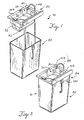
- FIG. 1 is a perspective view of one preferred embodiment made according to the present invention.
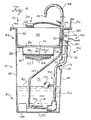
- FIG. 2 is a front, vertical cross-sectional view of FIG. 1.
- FIG. 3 is a perspective view of a second preferred embodiment made according to the present invention.
- FIG. 4 is a front, vertical cross-sectional view of FIG. 3.
- FIG. 5 is a front, vertical cross-sectional view of the parts washer in FIG. 3 including a pre-treatment center and an overflow detection device.
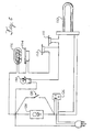
- FIG. 6 is an electrical schematic diagram of the components of modular controller.
- Referring now the drawings in detail, and more particularly to FIG. 1, a preferred embodiment of the invention is illustrated. A
parts washer 10 is shown for washing parts including automotive, industrial, and military parts, such as nuts, bolts, valves, pistons, carburetors, transmission parts, and the like, that have been fouled with organic and particulate matter. Theparts washer 10 is preferably manufactured from a plastic material. In one preferred embodiment of the invention, theparts washer 10 is constructed from a high density polyethylene. As those skilled in the art recognize, theparts washer 10 may also be made from a variety of materials including other plastics (e.g. polyvinyl chloride or polypropylene), as well as stainless steel, fiberglass, or the like without departing from the spirit and scope of the invention. - In a preferred embodiment, the
parts washer 10 generally comprises afirst chamber 20, such as a sink or basin, and asecond chamber 80, such as a tank or housing. Thefirst chamber 20 includesside walls 32 that extend downwardly to abottom panel 22 that has anopening 24 for draining awashing liquid 82 as shown in FIG. 2. Theside walls 32 and thebottom panel 22 of thefirst chamber 20 define acavity 26 for washing parts. Anupper ledge 28 andlower ledge 30 are preferably formed in thesidewalls 32 of thefirst chamber 20 for supporting various components of thepart washer 10. Theupper ledge 28 andlower ledge 30 preferably encircle thecavity 26 and overflow drain holes 34 are formed in theside walls 32 between theupper ledge 28 andlower ledge 30, as shown in FIG. 4. - Referring to FIGs. 3 and 4, a
false bottom member 36, aporous medium 38, and asupport grid 40 are preferably positioned within thefirst chamber 20. Thesupport grid 40 is preferably rectangular and positioned on thebottom panel 22 of thefirst chamber 20. Thesupport grid 40 is used to support theporous medium 38. - The
porous medium 38, such as a filter, rests upon thelower ledge 30 and thesupport grid 40. Theporous medium 38 may function to strain particulate matter from thewashing liquid 82 as well as a vehicle for bringing a microorganism in contact with thewashing liquid 82, as discussed below. Preferably, theporous medium 38 is rated between about 10 to 25 microns and does not have an affinity for hydrocarbons, such as polyester. As those skilled in the art will appreciate, theporous medium 38 may be constructed from a variety of materials such as cotton, cellulose, polyolefin fibers, polyester fibers, fiberglass, or the like without departing from the scope of the invention as defined in the claims. - The
false bottom member 36 is preferably positioned above theporous medium 38 on theupper ledge 28 such that thefalse bottom member 36 partitions thecavity 26. Thefalse bottom member 36 is capable of supporting a variety of parts to be cleaned. Thefalse bottom member 36 provides easy access to theporous medium 38 by allowing a user to simply lift thefalse bottom member 36 out of thecavity 26 to expose theporous medium 38. Thefalse bottom member 36 further contacts theside walls 32 of thefirst chamber 20. Thefalse bottom member 36 includes adrain hole 42 that may be closed or have a strainer (not shown) therein. - In a preferred embodiment, the
first chamber 20 has anouter ledge 44 that extends around its periphery and a back-splash 46 that extends upwardly from a rear portion of theouter ledge 44. Thefirst chamber 20 also has aflexible faucet 48 that extends from the rear portion of theouter ledge 44 and terminates in the form of anozzle 50. As those skilled in the art will appreciate, the size and shape of thefirst chamber 20 may be modified without departing from the scope of the invention. For example, theside walls 32,bottom panel 22,upper ledge 28,lower ledge 30,outer ledge 44, and back-splash 46 may be formed as a single, molded, unitary piece. - In a preferred embodiment of the present invention, an alarm may be used to indicate when there is an overflow of the
washing liquid 82 in thefirst chamber 20. Preferably, a thermo-sensor 81 may be used to detect heat from the washing liquid when it rises to a certain level in thefirst chamber 20. As those skilled in the art will recognize, other devices may be used to detect an overflow of thewashing liquid 82 in thefirst chamber 20. For example, as shown in FIG. 5, a lever 140 containing a spoon-like end may be mounted on a pivot orpin 144. The lever 140 is located below anoverflow outlet 146 of thefirst chamber 20 and is in contact with aswitch 142. The spoon-like end has a small hole at the bottom to let accumulated liquid drip out. However, when the liquid fills the spoon-like end faster than the liquid can drain out of the small hole, the lever 140 will pivot because of the weight of the fluid and actuate theswitch 142 triggering a warning lamp or buzzer. - Referring now to FIG. 2, the
second chamber 80 of theparts washer 10 has anupper end 84 and alower end 86. Thesecond chamber 80 includesside walls 88 and a bottom 90 that define acavity 92 therebetween. Thesecond chamber 80 may also include handles (not shown) at each end for lifting theparts washer 10. Thesecond chamber 80 may be constructed from a polyolefin plastic, preferably polyethylene. - As shown in FIG. 3, the
first compartment 20 may be mounted or secured to theupper end 84 of thesecond chamber 80. As those skilled in the art will appreciate, the arrangement of thefirst chamber 20 with thesecond chamber 80 as well as the size and shape of the chambers may be modified without departing from the scope of the invention. For example, thesecond chamber 80 may remain stationary while thefirst chamber 20 may be transported to a desired work area as shown in FIG. 1 and 3. In addition, theparts washer 10 may use the condensed water vapor from thesecond chamber 80 as a source of a clean distilled rinse water to rinse parts in thefirst chamber 20. - Referring now to FIG. 3 and 4, the parts washer includes a
modular controller 100 that is preferably fastened or mounted to thesecond chamber 80 by twoclamps 118. Themodular controller 100 has anupper portion 102 and alower portion 104. Themodular controller 100 preferably passes through ahole 106 in thesecond chamber 80 and is sealed to thesecond chamber 80 with a feed-throughdisc 108. As those skilled in the art will recognize, themodular controller 100 may be modified without departing from the spirit and scope of the invention. For example, the modular controller may be disposed completely outside of thesecond chamber 80. Thus, if the modular controller is disposed outside the tank, the heater could transmit heat through the side or bottom of thesecond chamber 80 and the temperature sensor could detect the temperature of thewashing liquid 82 through the walls or bottom of thesecond chamber 80. In this configuration, the heater may be a flat pad, and the level sensor could detect the weight of thewashing liquid 82 by sensing the force of fluid on the bottom of the tank. - The
modular controller 100 further includes aheater 110,thermostat 111, and high limit protection thermostat 112 (see FIG. 6) that are coupled to thelower portion 104 of themodular controller 100. Alevel probe 116, such as a float actuated switch having a switch equipped float, and overtemperature protection thermostat 114 may also be attached to thelower portion 86 of themodular controller 100 to monitor the level of thewashing liquid 82 and to limit the sheath temperature of theheater 110. - The
thermostat 111 cycles power to theheater 110 to heat thewashing liquid 82 to a desired temperature. Thewashing liquid 82 is preferably maintained in a temperature range which supports an environment for microorganisms employed within theparts washer 10. Preferably, the washing liquid is heated between about 105 to 115 degrees Fahrenheit. When thethermostat 111 senses that the temperature of thewashing liquid 82 within thesecond chamber 80 is below a desired temperature, theheater 110 is turned on, and when thethermostat 111 senses that the temperature of thewashing liquid 82 is at or above the desired temperature, theheater 110 is turned off. - The high limit protection thermostat 112 turns off the
heater 110 if thethermostat 111 does not open and the temperature of the fluid reaches about 135 degrees F. The overprotection thermostat 114 interrupts power to theheater 110 if the sheath temperature of theheater 110 reaches 170 degrees F. Theheater 110 is further controlled by a level switch 117 of thelevel probe 116. When the level switch 117 senses a low level of thewashing liquid 82, the level switch 117 disables theheater 110 and causes a low level warning buzzer to sound. - Referring now to FIG. 6, a
warning buzzer 150 is wired across the high limit protection thermostat 112, the overtemperature protection thermostat 114, and the level switch 117 to sound a warning should any of these components be open and thethermostat 111 is closed. In normal operation, thebuzzer 150 will also indicate the need formore washing liquid 82. Continued operation of thebuzzer 150 after fluid level is restored indicates a thermostat or component failure and may require a replacementmodular controller 100. - In a preferred embodiment, the
modular controller 100 is in electrical communication with acirculation mechanism 124, such as a pump or a pneumatic column pump. Thecirculation mechanism 124 plugs into a receptacle 126 of themodular controller 100 and is disposed in thesecond chamber 80. Thecirculation mechanism 124 also has aliquid transfer line 129, such as a tube or conduit, that extends to thefirst chamber 20. The circulatingmechanism 124 is preferably activated when motion is sensed in thefirst chamber 20 or when abrush 123 is used. In order for motion to be detected in thefirst chamber 20, thefirst chamber 20 andsecond chamber 80 have an opening in one of their sides to allow amotion sensing device 128 to detect motion. Themotion sensing device 128 is integrated with a timer switch (not shown). For example, thecirculation mechanism 124 will automatically shut off after the motion sensing device does not detect activity in thefirst chamber 20 for about four minutes. - The
circulation mechanism 124 may also be manually activated byswitch 130, such as an electrical switch or pneumatic switch, in order to allow continuous operation of thecirculation mechanism 124 for a steady flow of washingliquid 82 over a part, to empty the liquid into a bucket, or in the event the sensor malfunctions. As those skilled in the art will recognize, the switch may take many forms such as a foot switch without departing from the scope of the invention. If themotion sensor 128 and switch 130 of modular controller fail, thecirculation mechanism 124 may be plugged directly into a receptacle, such as a wall receptacle, until themodular controller 100 is replaced or fixed. Thus, the user is able to wash parts during most failure conditions. As those skilled in the art will recognize, theparts washer 10 may have a plurality of circulation mechanisms without departing from the spirit and scope of the invention. For example, a circulation mechanism may be used in conjunction with thefirst chamber 20 for circulating thewashing liquid 82 only in thefirst chamber 20. In addition, the flow rate of thewashing liquid 82 in thefirst chamber 20 may be at a different rate than the flow rate of thewashing liquid 82 between the first and second chambers. - As shown in FIG. 5, the device may be equipped with
pre-treatment chamber 60, such as a tank. Thepre-treatment chamber 60 may be used alone as a soaker tank or with theparts washer 10. Thepre-treatment chamber 60 is preferably molded in polyolefin plastic, such as polyethylene. Aflexible tube 62, made of rubber or plastic, is preferably attached through theside 61 of thechamber 60. Thetube 62 may be held by a clip orretainer 44 in an upright position to prevent thewashing liquid 82 from draining into thepart washer 10 or a waste receptacle. Thepretreatment chamber 60 also has aporous medium pad 66 which is preferably in contact with aplastic film bag 68, which may have anelastic perimeter band 70. Theelastic perimeter band 70 fits into agroove 72 in thepre-treatment chamber 60. A porousmedium support 68 is placed under theporous medium pad 66 to provide a reservoir for thewashing liquid 82. Theporous medium pad 66 filters harmful fibers, such as asbestos, from thewashing liquid 82 if used to clean automotive brakes. Because thewashing fluid 82 in thepre-treatment chamber 60 can be retained until the organic matter is virtually eliminated, thepre-treatment chamber 60 allows waste to be discharged into publicly operated treatment facilities or into theparts washer 10. - The
second chamber 80 of thepart washer 10 is preferably filled with awashing liquid 82 for separating organic matter from objects. Thewashing liquid 82 is not toxic to microorganisms. Thewashing liquid 82 is used to separate organic and particulate waste from the parts washed in thefirst chamber 20. Preferably, thewashing liquid 82 is a free flowing aqueous solution with a specific gravity of 1.083, including a slight pleasant odor, no flash point, a boiling point of 210 degrees Fahrenheit, a pH of approximately seven, and infinitely soluble in water. Thewashing liquid 82 is preferably a mixture of pH neutral emulsifiers and surfactants containing no volatile organic compounds, phosphates, formaldehyde, biocides, or other toxic materials. The emulsifier and surfactants are blended in liquid form to produce a biodegradable, non-toxic, non-caustic, non-flammable oil dispersant cleaner and degreaser. A suitable washing liquid is available from Advanced Bioremediation Systems, such as Surfzyme™ (solution # 5 in Table 1), or Safeworld Products SW-2. - In a preferred embodiment, a biological component is added to the
washing liquid 82 to break down organic wastes in thewashing liquid 82. The biological component is preferably in the form of microorganisms that biodegrade organic compounds, such as hydrocarbons, oils, greases, petroleum by-products, creolates, and other carbon based compositions. The microorganisms generally convert hydrocarbon compounds and chlorinated solvents into elements of water, carbon dioxide, and other digestion products. The microorganisms are preferably nonpathogenic and may include those from the genera Bacillus, Micrococcus, Acinetobacter, Rhodococcus, Nocardia, Pseudomonas, Flavobacterium, Saccharomyces, Candida, and White Rot Fungus. However, microorganisms which may degrade other carbon based compositions, i.e. the long-chain polymers compounds found in structural plastics such as the polyolefins, styrenes, neoprenes, and the like, are not suitable if the physical structure of the parts washer or the parts being washed is degradable by the microorganisms. Suitable microorganisms are available from ABS Inc. of Duluth, Georgia, part Number PWM-25 or from Louisiana Remediation as LRC-1. - As shown in Table 1-3, various combinations of microorganism are provided that dissolve grease. Individual formulations can be developed by using at least one generum from each group of activity, including chlorinated organics depending upon the requirements for this activity. As those skilled in the art will recognize, there are other suitable microorganisms that are well known in the art and may be used without departing from the scope of the invention.
- Although the microbes disclosed herein are combined, there is no guarantee of compatibility. Even species within a genus may or may not be compatible. There are no hard and fast rules regarding combinations and most academic work done has been in pure culture so there are no guidelines. It is general knowledge that most manufactures of microbes use up to 5 genera and 15 different species in total just for hydrocarbon degradation. The actual role of each species is generally completely undefined after 20 years of such business activity.
- The microorganisms are preferably added directly to the
washing liquid 82 of thepart washer 10 in a dormant state. As those of skill in the art will recognize, the microorganisms may be added to theparts washer 10 in a variety of ways without departing from the scope of the invention. For example, the microorganisms may be attached to the porous medium with an adhering agent, such as 3M Super 77 adhesive, or an encapsulatingagent 84 that is water soluble, and then released when thewashing liquid 72 is introduced into the porous medium. - The microorganisms may also be subjected to a preservation technique in an effort to ensure their viability in the field and their resistance to environmental shock. For example, nutrient and buffer components, such as agar, and water soluble adhesives, such as gum, are preferably mixed with the microorganisms to promote stability of the microorganisms prior to mixing the microorganisms with a carrier. The carrier is preferably composed of inert and nutrient organic materials that preserve and protect the microorganisms during storage and transportation. As those skilled in the art will recognize, the microorganisms may be employed in combination with nitrifying or denitrifying bacteria, phosphate solubilizing strains of microorganisms, bioemulsifier producing strains of microorganisms, and strains of microorganisms which produce growth factors, such as B-vitamins, without departing from the scope of the invention.
- Critical macronutrients, such as nitrogen and phosphorus, may also be combined with the microbial formulation or blended with the surfactant to enhance biodegradation for the oil and grease. Likewise, micro-nutrients may be limited in certain cases that require supplementing. Micronutrients requirements for effective biological oxidation and a Figure indicating the benefit of nutrient addition versus enhanced BOD removal is provided in Tables 2 and 3.
- In using the
part washer 10, an operator places an object in thefirst chamber 20. When motion is detected in thefirst chamber 20, thecirculation mechanism 124 circulates thewashing liquid 82 from thesecond chamber 80 through theconduit 48 andnozzle 50 or pressurized spray jets to thefirst chamber 20 to wash the surfaces of the object in contact with thewashing liquid 82. Thewashing liquid 82 is used to separate organic waste from the object being washed. Thewashing liquid 82, along with the organic waste and any small particulate washed from the part, then flows by gravity through thedrain hole 42 of thefalse bottom member 36. The strainer (not shown) will, of course, keep certain objects from passing through thedrain hole 42. Thereafter, thewashing liquid 82, organic waste, and remaining matter then flow into the cavity or opening containing theporus medium 38. - The porous medium 38 traps the particulate matter and allows the organic contaminants and washing
liquid 82 to pass therethrough. Because theporous medium 38 does not collect the organic contaminants, it is capable of being disposed of as solid waste. If the porous medium 38 contains microorganisms, thewashing liquid 82 will release the microorganisms. The released microorganisms then flow with thewashing liquid 82 and organic contaminants through thesupport grid 40 into thesecond chamber 80. If the flow of thewashing liquid 82 becomes obstructed in thefirst chamber 20, thewashing liquid 82 may flow through a pair of supplemental drain holes 34 defined through the rear of thesecond chamber 80 as shown in FIG. 4. - In the
second chamber 80, a large percentage of the microorganisms and organic contaminants will tend to accumulate proximate to the surface of thewashing liquid 82 such that a large portion of the biodegradation takes place proximate to the surface of thewashing liquid 82. This forms a vapor barrier that tends to minimize the evaporation of thewashing liquid 82. The vapor may be condensed, collected, and used in a closed-loop source for rinsing. If organic waste increasingly accumulates toward the surface of thewashing liquid 82 in thesecond chamber 80, the microorganisms may need to be replenished. Because theporous medium 38 removes the particulate matter and the microorganisms digest the organic waste, thesecond chamber 80 usually does not need to be dredged of any waste. Finally, thewashing liquid 82 is re-circulated to thefirst chamber 20. As those skilled in the art will recognize, the temperature, pressure, or flow of thewashing liquid 82 in thefirst chamber 20 may be greater or less than in thesecond chamber 80 without departing from the scope of the invention. Further, the temperature, pressure, or flow of thewashing liquid 82 in thefirst chamber 20 may not be optimum for bioremediation. - Although the present invention has been described in detail by way of illustration and example, various changes and modifications may be made without departing in any way from the invention an the scope of the appended claims.
TABLE 1 Genera Low MW Organic Fractions Aromatics Alkanes Polyaromatic Hydrocarbons (PAH) Chlorinated Organics 1 +++ 2 + ++ + ++ ++ 3 + + ++ ++ 4 + + 5 + + + 6 + 7 + ++ ++ ++ 8 + + ++ 9 + ++ 10 + ++ 11 + ++ ++ 12 + ++ ++ 13 + ++ ++ 14 ++ 15 + ++ ++ +++ +++ 16 + + ++ 17 + +++ 18 + ++ + ++ 1. Bacillus spp. 2. Pseudomonas spp. 3. Rhodococcus spp.
4. Micrococcus spp. 5. Acinetobacter spp. 6. Arthrobacter spp.
7. Nocardia spp. 8. Alcaligenes spp. 9. Flavobacterium spp.
10. Mucor spp. 11. Candida spp. 12. Saccharomyces spp.
13. Aspergillus spp. 14. Geotrichum spp. 15. White Rot Fungus
16. Rhizopum spp. 17. Beirjerinckie spp. 18. Aeromonas spp.
+ Moderate activity
++ Good activity
+++ Very good activityTABLE 2 Operational Parameters - Micro-nutrients • Micro-nutrient or trace nutrients are required in much smaller quantities than N & P Trace Nutrient Requirements for Biological Oxidation - (mg/mgBOD) Na 5 x 10⁵ - ion balance K 45 x 104 - activates synthesis of peptides and coenzyme for enolase in EMP Ca 62 x 10-4 - ion balance and heat resistance in spores Mg 30 x 10-4 - cofactor for phosphorylating enzymes - energy production Fe 12 x 10-3 - cytochrome oxidase, ferritin and catalase Mn 10 x 10-5 - may often replace role of Mg Cu 14.6 x 10⁻⁵ - cofactor in certain bacteria Zn 16 x 10-5 - alcohol dehydrogenase Co 13 x 10-5 - vitamin B12 - required by methanogens Mo 43 x 10-5 - nitrate reductase and hydrogenase enzymes of methanogens Se 14 x 10-10 - can be very toxic, but is also essential CO3 27 x 10-4 - buffering S - cysteine and methionine, thiol groups of coenzymes - CoA Conflated from Eckenfelder - principles of Water Quality Management, page 305 and Whiteman (1985), PhD thesis
Claims (20)
- A closed system for cleaning automotive parts, equipment parts and machinery parts fouled with organic matter, the system (10) comprising:(a) a first chamber (20) for cleaning the parts by contacting with an aqueous fluid; and(b) a second chamber (80) that holds the fluid and houses a plurality of live microorganisms that biodegrade the organic matter in the fluid and the fluid circulates from the second chamber (80) to the first chamber (20) to be available to clean parts and drains off from the first chamber (20) to the second chamber (80), whereby the drain (24) is at the bottom of the first chamber, characterized in that said microorganisms flow with said fluid.
- The system according to claim 1 wherein the fluid is a surfactant fluid that cleans organic matter from the parts.
- The system of claim 1 wherein the microorganisms are selected from the group consisting of the genus Bacillus, Micrococcus, Acinetobacter, Rhizopum, Arthrobacter, Alcaligenes, Aeromonas, Beirjerinckie, Mucor, Aspergillus, Geotrichum, Rhodococcus, Nocardia, Pseudomonas, Flavobacterium, Saccharomyces, Candida, and White Rot Fungus.
- The system of claim 1 wherein the microorganisms are affixed to a porous medium (38) and are released from said porous medium by contacting with said fluid.
- The system of claim 1 further comprising a porous medium (38) for trapping particulate matter.
- The system of claim 5 wherein the porous medium (38) comprises a filter.
- The system of claim 1 further comprising a circulating mechanism (124) to move the fluid between the first chamber (20) and the second chamber (80) to form a closed loop re-circulation.
- The system of claim 1 further comprising a controller (100) in communication with the circulating mechanism (124).
- The system of claim 8 wherein the controller (100) is modular.
- The system of claim 1 further comprising a heating mechanism (110; 111) to heat the washing fluid to a desired temperature.
- The system of claim 1 wherein the first chamber (20) has a sensor (81) to detect the level of washing fluid in the first chamber (20).
- The system of claim 1 further comprising a sensor (116) for monitoring the level of the fluid in the second chamber (80).
- The system of claim 1 further comprising a motion sensor (128), wherein a circulation mechanism (124) is activated when motion is detected by said motion sensor (128).
- The system of claim 1 further comprising a switching mechanism (130) for activating a circulating mechanism (124).
- The system of claim 1 further comprising a third chamber (60) for receiving articles to be washed, the third chamber (60) capable of being positioned within the first chamber (20).
- The system of claim 1 further comprising a second circulating mechanism for circulating the washing fluid in the first chamber (20).
- The system of claim 9 wherein the modular controller (100) comprises:a housing having an upper (102) and lower (104) portion;a motion sensor (128) coupled to the upper portion (102);a heater (110) coupled to the lower portion (104); anda level detector (116) coupled to the lower portion (104).
- A method of washing within a system according to claim 1 comprising the steps of:placing an article in a first chamber (20);circulating a washing fluid from a second chamber (80) to the first chamber (20) to wash the surfaces of the article in contact with the fluid;draining the washing fluid from the first chamber (20) into the second chamber (80), through a drain (24) at the bottom of the first chamber;removing organic matter in the washing fluid wherein the step of removing the organic matter from the fluid comprises biologically degrading the organic matter; andre-circulating the washing fluid from the second chamber (80) to the first chamber (20), wherein said microorganisms flow with said washing fluid.
- The method of claim 18 further comprising the step of passing the washing fluid through a porous medium (38).
- The method of claim 18 or 19 further comprising the step of environmentally controlling the fluid to provide a desired bioremediation condition.
Priority Applications (2)
| Application Number | Priority Date | Filing Date | Title |
|---|---|---|---|
| DE1995222341 DE29522341U1 (en) | 1994-09-30 | 1995-09-29 | Microbiological parts washer |
| EP20020000396 EP1197269A3 (en) | 1994-09-30 | 1995-09-29 | Microbiological parts washer |
Applications Claiming Priority (5)
| Application Number | Priority Date | Filing Date | Title |
|---|---|---|---|
| US31590294A | 1994-09-30 | 1994-09-30 | |
| US315902 | 1994-09-30 | ||
| US37089895A | 1995-01-10 | 1995-01-10 | |
| US370898 | 1995-01-10 | ||
| PCT/US1995/013042 WO1996011072A2 (en) | 1994-09-30 | 1995-09-29 | Microbiological parts washer |
Related Child Applications (2)
| Application Number | Title | Priority Date | Filing Date |
|---|---|---|---|
| EP20020000396 Division EP1197269A3 (en) | 1994-09-30 | 1995-09-29 | Microbiological parts washer |
| EP02000396.8 Division-Into | 2002-01-07 |
Publications (5)
| Publication Number | Publication Date |
|---|---|
| EP0784518A2 EP0784518A2 (en) | 1997-07-23 |
| EP0784518A4 EP0784518A4 (en) | 1998-12-23 |
| EP0784518B1 EP0784518B1 (en) | 2002-06-26 |
| EP0784518B8 EP0784518B8 (en) | 2003-01-08 |
| EP0784518B2 true EP0784518B2 (en) | 2007-10-10 |
Family
ID=26980122
Family Applications (2)
| Application Number | Title | Priority Date | Filing Date |
|---|---|---|---|
| EP19950936304 Expired - Lifetime EP0784518B2 (en) | 1994-09-30 | 1995-09-29 | Microbiological parts washer |
| EP20020000396 Withdrawn EP1197269A3 (en) | 1994-09-30 | 1995-09-29 | Microbiological parts washer |
Family Applications After (1)
| Application Number | Title | Priority Date | Filing Date |
|---|---|---|---|
| EP20020000396 Withdrawn EP1197269A3 (en) | 1994-09-30 | 1995-09-29 | Microbiological parts washer |
Country Status (14)
| Country | Link |
|---|---|
| US (3) | US6571810B1 (en) |
| EP (2) | EP0784518B2 (en) |
| JP (1) | JPH10506797A (en) |
| KR (1) | KR100362009B1 (en) |
| CN (1) | CN1167517C (en) |
| AT (1) | ATE219704T1 (en) |
| AU (1) | AU709648B2 (en) |
| BR (1) | BR9509114A (en) |
| CA (2) | CA2201314C (en) |
| DE (2) | DE29522341U1 (en) |
| ES (1) | ES2176341T5 (en) |
| MX (1) | MX9702387A (en) |
| PT (1) | PT784518E (en) |
| WO (1) | WO1996011072A2 (en) |
Families Citing this family (45)
| Publication number | Priority date | Publication date | Assignee | Title |
|---|---|---|---|---|
| AU3823595A (en) * | 1994-09-30 | 1996-05-02 | Chemfree Corporation | Parts washing system |
| US6571810B1 (en) | 1994-09-30 | 2003-06-03 | Zymo International, Inc. | Parts washing system |
| DE10032351A1 (en) * | 1999-07-23 | 2001-01-25 | Heidelberger Druckmasch Ag | Inking mechanism in off-set printer has ultra sound transmitter producing ultrasonic vibrations in exposed surface section carrying wetting agent to atomise same |
| IT1319025B1 (en) | 2000-10-26 | 2003-09-19 | Rosauto Srl | WASHING TANK FOR BRAKES OF INDUSTRIAL AND SIMILAR VEHICLES. |
| US6503394B1 (en) * | 2000-11-15 | 2003-01-07 | Stephen A. Hoyt | Digester method and system for processing farm waste |
| FR2824802B1 (en) * | 2001-05-15 | 2003-08-15 | Culasse Europ Service | DEVICE FOR CLEANING AUTOMOTIVE PARTS |
| US20030203118A1 (en) * | 2002-04-26 | 2003-10-30 | Wickes Roger D. | Oscillating dispersion apparatus, system, and method |
| US6762047B2 (en) | 2002-06-24 | 2004-07-13 | Osprey Biotechnics, Inc. | Bacterial parts washer, composition and method of use |
| FR2844464B1 (en) * | 2002-09-16 | 2006-04-14 | Fillon Investissement | INSTALLATION FOR CLEANING VARIOUS OBJECTS |
| DE10252634A1 (en) * | 2002-11-11 | 2004-05-27 | Umwelttechnik Georg Fritzmeier Gmbh & Co. | Purification of sewage or other substances laden with harmful organic matter and detergent or clarifying agent also useful laundry and cleaning surfaces involve introduction of photosensitizer releasing singlet oxygen when stimulated |
| KR20050103916A (en) * | 2003-02-04 | 2005-11-01 | 포워드 테크놀로지 에이 크레스트 그룹 컴퍼니 | Ultrasonic cleaning tank |
| US6874512B2 (en) * | 2003-04-10 | 2005-04-05 | Safety-Kleen Systems, Inc. | Parts washer with improved temperature and pump control |
| FR2854824B1 (en) * | 2003-05-16 | 2005-07-08 | Clean 3 Bio System | PROCESS AND INSTALLATION FOR CLEANING PARTS SOILED BY ORGANIC MATTER BY BIO-DEPOLLUTION |
| US7128075B2 (en) * | 2003-12-01 | 2006-10-31 | Safety-Kleen Systems, Inc. | Parts washing apparatus |
| KR100522716B1 (en) * | 2004-02-20 | 2005-10-19 | 학교법인 한림대학교 | Removal method for methyl ethyl ketone using geotrichum-immobilized biofilter |
| GB0405337D0 (en) * | 2004-03-09 | 2004-04-21 | Petty Robert H | Paint spraygun cleaner |
| US7674251B2 (en) * | 2004-04-08 | 2010-03-09 | Boston Scientific Scimed, Inc. | Medical devices including aerated adhesive bonds and methods of forming the same |
| US20050273955A1 (en) * | 2004-06-11 | 2005-12-15 | Rogus Thomas E | Bar stock degreasing machine |
| EP1872874A1 (en) * | 2006-06-30 | 2008-01-02 | Ulrich Berens | Apparatus for cleaning machinery components soiled with oil or grease |
| DE102006036633A1 (en) * | 2006-08-03 | 2008-02-07 | Schickert Gmbh & Co. Kg | Small parts and machine parts cleaning method, involves attaching cleaning device to water pipeline and determining operating pressure forming water line network, where operating pressure lies between preset values |
| US7740711B2 (en) * | 2006-11-02 | 2010-06-22 | Safety-Kleen Systems, Inc. | Parts washer heater pump module |
| US20080210260A1 (en) * | 2007-03-02 | 2008-09-04 | Safety-Kleen Systems, Inc. | Multipurpose Aqueous Parts Washer |
| US8220471B2 (en) * | 2007-03-02 | 2012-07-17 | Safety-Kleen Systems, Inc. | Multipurpose aqueous parts washer |
| US20080303388A1 (en) * | 2007-06-07 | 2008-12-11 | Petrovich Andy | Surgical cart with a mister |
| DE102007034464B4 (en) * | 2007-07-20 | 2011-07-14 | ph-cleantec GmbH, 70736 | cleaner |
| KR100915960B1 (en) * | 2007-07-25 | 2009-09-10 | (주)클레슨 | Bio ultrasonic washing device |
| EP2222380A1 (en) * | 2007-11-28 | 2010-09-01 | Wasabi (Holdings) Pty Ltd. | Liquid treatment apparatus |
| US8141477B2 (en) * | 2008-05-13 | 2012-03-27 | William Broderick | Mash/lauter tun and method of use thereof |
| ITPD20080262A1 (en) * | 2008-09-12 | 2010-03-12 | Vemec S R L | EQUIPMENT FOR WASHING AIRBRUSHERS AND / OR FOR WASHING SMALL PIECES |
| CA2689723A1 (en) * | 2010-01-05 | 2011-07-05 | Jacques St-Pierre | Bioremediation device |
| HUE028196T2 (en) * | 2010-08-02 | 2016-12-28 | Nch Corp | Parts washer and method of washing parts |
| WO2012174483A2 (en) * | 2011-06-17 | 2012-12-20 | Duke Manufacturing Co. | Kitchenware washing assemblies and related methods |
| GB201117910D0 (en) * | 2011-10-15 | 2011-11-30 | Safety Kleen Europ Ltd | Parts washing machiine |
| CN102580956B (en) * | 2012-02-20 | 2014-01-29 | 陕西科技大学 | Equipment and method for cleaning internal wall of capillary stainless steel tube |
| USD750852S1 (en) * | 2012-09-07 | 2016-03-01 | Sata Gmbh & Co. Kg | Paint spray gun cleaning device |
| USD733979S1 (en) | 2012-10-26 | 2015-07-07 | Chemfree Corporation | Parts washer |
| USD747567S1 (en) | 2012-10-26 | 2016-01-12 | Chemfree Corporation | Parts washer |
| USD735957S1 (en) | 2012-10-29 | 2015-08-04 | Chemfree Corporation | Parts washer |
| US9132455B2 (en) | 2012-10-29 | 2015-09-15 | Chemfree Corporation | Portable parts washer |
| MX358003B (en) | 2013-03-22 | 2018-07-25 | Decisiones Ambientales S A De C V | System and method for washing mechanical parts. |
| KR101489439B1 (en) * | 2013-05-16 | 2015-02-03 | 경북대학교 산학협력단 | Cleansing Device of organic matter using of Effective Microorganism |
| EP3187272B1 (en) * | 2015-12-30 | 2022-08-31 | Bio-Circle Surface Technology GmbH | Station for purification of tools or system parts contaminated by varnishes and paints and cleaning method in a stationary system |
| BE1024938B1 (en) * | 2017-01-25 | 2018-08-27 | Living Technologies Coöperatieve Vennootschap Met Beperkte Aansprakelijkheid | Method for cleaning surfaces in interior spaces and in technical installations |
| KR101869643B1 (en) * | 2017-02-27 | 2018-07-20 | 문태주 | Eco-friendly recycled IT clean system |
| US11285505B2 (en) * | 2019-12-19 | 2022-03-29 | MTI Baths, Inc. | Waterfall sink |
Family Cites Families (53)
| Publication number | Priority date | Publication date | Assignee | Title |
|---|---|---|---|---|
| SU80983A1 (en) | 1948-12-13 | 1949-11-30 | Ф.В. Соловей | Device for washing and degreasing parts |
| US2675012A (en) * | 1952-10-18 | 1954-04-13 | Frank J Scales | Washing apparatus for automotive and machine parts and assmeblies |
| US3352310A (en) | 1965-03-15 | 1967-11-14 | Robert E Doyscher | Parts washer |
| US3378019A (en) * | 1966-04-08 | 1968-04-16 | Albert Armato | Parts washers |
| US3522814A (en) * | 1968-12-06 | 1970-08-04 | Safety Kleen Corp | Washer for parts and the like |
| US3856667A (en) | 1970-06-03 | 1974-12-24 | Bioteknika Int Inc | Microbial degradation of petroleum |
| US3707404A (en) | 1971-05-12 | 1972-12-26 | Build All Fabricating Inc | Parts washer and method of solvent cleaning |
| SU452392A1 (en) | 1972-08-07 | 1974-12-05 | Уральский автомобильный завод | Punch for editing hollow parts |
| US3970560A (en) * | 1974-09-20 | 1976-07-20 | Metzger Herman U | Parts washer |
| US3960728A (en) * | 1975-03-12 | 1976-06-01 | Safety-Kleen Corporation | Disposable filter apparatus |
| US3971394A (en) | 1975-04-28 | 1976-07-27 | Osborne Irving R | Apparatus for cleaning vehicle parts |
| US4056114A (en) | 1975-06-03 | 1977-11-01 | Boutillette Arthur A | Parts washer and filter assembly therefor |
| US4213475A (en) | 1979-02-05 | 1980-07-22 | Minkin Gary E | Power parts washer |
| US4351729A (en) | 1980-02-06 | 1982-09-28 | Celanese Corporation | Biological filter and process |
| US4407717A (en) | 1980-12-08 | 1983-10-04 | Sterling Drug Inc. | Wastewater treatment process |
| US4925564A (en) * | 1985-02-25 | 1990-05-15 | Robert B. Grubbs | Bacterial incubator and method of use |
| US4670149A (en) * | 1985-02-25 | 1987-06-02 | John Francis | Bacterial incubator and method of use |
| US4713343A (en) | 1985-08-29 | 1987-12-15 | The United States Of America As Represented By The Administrator Of The U.S. Environmental Protection Agency | Biodegradation of halogenated aliphatic hydrocarbons |
| SU1496841A1 (en) | 1987-01-05 | 1989-07-30 | М. И. Кубицкий | Installation for washing articles |
| US4952315A (en) * | 1987-05-05 | 1990-08-28 | Nabil Saab | Method, system and emulsifier substance for treatment of materials containing harmful substances |
| SE8801511L (en) * | 1987-09-21 | 1989-03-22 | Lars Aake Hilmer Haakansson | DEFROSTING PROCEDURE AND DEVICE THEREOF |
| US4765020A (en) * | 1987-11-30 | 1988-08-23 | Weihe Clyde R | Silverware washing machine |
| DE3815271A1 (en) * | 1988-05-05 | 1989-11-16 | Sandoz Ag | METHOD FOR CLEANING INDUSTRIAL SEWAGE |
| US5037551A (en) | 1988-12-19 | 1991-08-06 | Weyerhaeuser Company | High-flow rate capacity aerobic biological dehalogenation reactor |
| US4995409A (en) * | 1990-01-29 | 1991-02-26 | Watts Craig L | Automotive parts washer utilizing a volatile cleaning solution |
| US5039415A (en) | 1990-04-23 | 1991-08-13 | Smith Alvin J | Decontamination of hydrocarbon contaminated soil |
| RU2014286C1 (en) | 1990-05-24 | 1994-06-15 | Государственный научно-исследовательский институт биосинтеза белковых веществ | Method for water and soil purification of oil products |
| NL9100063A (en) * | 1991-01-15 | 1992-08-03 | Pacques Bv | METHOD AND APPARATUS FOR THE BIOLOGICAL TREATMENT OF SOLID ORGANIC MATERIAL |
| US5401413A (en) * | 1991-02-11 | 1995-03-28 | Yissum Research Development Company Of The Hebrew University Of Jerusalem | Method for enhancing the biodegradation of biodegradable organic wastes |
| WO1992016314A1 (en) | 1991-03-12 | 1992-10-01 | Haakansson Lars | A device for cleaning objects, preferably of metal |
| DE4116082C2 (en) * | 1991-05-16 | 1994-10-20 | Dlk Ventilatoren Gmbh | Process and device for waste water treatment in car washes |
| US5209851A (en) * | 1991-06-11 | 1993-05-11 | Hume Frank C | Remediation methods for toxic materials |
| US5225083A (en) * | 1991-08-12 | 1993-07-06 | Pappas Thomas C | Method for bioremediation of grease traps |
| DE4209052A1 (en) | 1991-08-16 | 1993-02-25 | Peter Prof Dr Kunz | Microbial degreasing without separate waste water treatment - using microorganisms for grease and oil removal and decomposition |
| DE4138400C1 (en) * | 1991-11-22 | 1993-02-18 | Aichelin Gmbh, 7015 Korntal-Muenchingen, De | |
| US5935843A (en) * | 1992-02-13 | 1999-08-10 | Osprey Biotechnics, Inc. | Method and apparatus for waste degradation |
| US5413713A (en) * | 1992-04-15 | 1995-05-09 | Day; Donal F. | Method for increasing the rate of anaerobic bioremediation in a bioreactor |
| WO1993022245A1 (en) * | 1992-05-04 | 1993-11-11 | Allied-Signal Inc. | Apparatus and process for removal of pollutants from waste water |
| DE4225967A1 (en) * | 1992-08-06 | 1994-02-10 | Dyckerhoff & Widmann Ag | Process for the treatment of oil-water emulsions, in particular from car washes |
| DE69327023T2 (en) * | 1992-09-14 | 2000-07-13 | Haldor Aamot | Cleaning and rinsing processes for industrial products |
| US5303725A (en) | 1993-02-18 | 1994-04-19 | Kleer-Flo Company | Machine part cleaning apparatus |
| JPH0785767B2 (en) * | 1993-03-09 | 1995-09-20 | 栄一 吉田 | Filtration device |
| US5314620A (en) * | 1993-04-02 | 1994-05-24 | Harvey Universal, Inc. | Cutting oil treatment |
| US5398708A (en) | 1993-04-16 | 1995-03-21 | Sheldon; Morris W. | Parts cleaning machine |
| US5413714A (en) | 1993-04-16 | 1995-05-09 | Alliedsignal Inc. | Process for biological remediation of vaporous pollutants |
| JP2963317B2 (en) * | 1993-09-27 | 1999-10-18 | 日本バイリーン株式会社 | Three-dimensional nonwoven fabric and method for producing the same |
| DE4340058A1 (en) * | 1993-11-24 | 1995-06-01 | Aamot Haldor | Cleaning method for degreasing baths using micro-organisms |
| US5368653A (en) | 1994-01-10 | 1994-11-29 | Layfield Company, Inc. | Parts washer for cleaning mechanical parts |
| US5364789A (en) * | 1994-01-14 | 1994-11-15 | Guinn Lloyd J | Microbial cleaner |
| US6069002A (en) * | 1994-04-11 | 2000-05-30 | Aplc, Inc. | System and process for in tank treatment of crude oil sludges to recover hydrocarbons and aid in materials separation |
| US5492139A (en) * | 1994-08-01 | 1996-02-20 | B&S Research, Inc. | Method and apparatus for remediating contaminated material |
| US6571810B1 (en) * | 1994-09-30 | 2003-06-03 | Zymo International, Inc. | Parts washing system |
| EP4209052A1 (en) | 2021-01-14 | 2023-07-12 | ZTE Corporation | Methods, devices, and systems for configuring enhanced non-public network |
-
1995
- 1995-08-04 US US08/511,506 patent/US6571810B1/en not_active Expired - Fee Related
- 1995-09-29 BR BR9509114A patent/BR9509114A/en not_active IP Right Cessation
- 1995-09-29 EP EP19950936304 patent/EP0784518B2/en not_active Expired - Lifetime
- 1995-09-29 EP EP20020000396 patent/EP1197269A3/en not_active Withdrawn
- 1995-09-29 KR KR1019970701963A patent/KR100362009B1/en not_active IP Right Cessation
- 1995-09-29 ES ES95936304T patent/ES2176341T5/en not_active Expired - Lifetime
- 1995-09-29 CN CNB951964992A patent/CN1167517C/en not_active Expired - Fee Related
- 1995-09-29 JP JP51269696A patent/JPH10506797A/en active Pending
- 1995-09-29 WO PCT/US1995/013042 patent/WO1996011072A2/en active IP Right Grant
- 1995-09-29 AU AU38302/95A patent/AU709648B2/en not_active Ceased
- 1995-09-29 DE DE1995222341 patent/DE29522341U1/en not_active Expired - Lifetime
- 1995-09-29 PT PT95936304T patent/PT784518E/en unknown
- 1995-09-29 CA CA 2201314 patent/CA2201314C/en not_active Expired - Fee Related
- 1995-09-29 DE DE1995627209 patent/DE69527209T3/en not_active Expired - Lifetime
- 1995-09-29 MX MX9702387A patent/MX9702387A/en not_active IP Right Cessation
- 1995-09-29 CA CA 2435648 patent/CA2435648A1/en not_active Abandoned
- 1995-09-29 AT AT95936304T patent/ATE219704T1/en active
-
1997
- 1997-06-02 US US08/867,586 patent/US6318387B1/en not_active Expired - Lifetime
-
2001
- 2001-08-08 US US09/925,634 patent/US6440226B2/en not_active Expired - Fee Related
Also Published As
| Publication number | Publication date |
|---|---|
| AU709648B2 (en) | 1999-09-02 |
| CA2201314C (en) | 2003-12-16 |
| DE69527209T2 (en) | 2003-02-06 |
| US20020017314A1 (en) | 2002-02-14 |
| CA2201314A1 (en) | 1996-04-18 |
| ATE219704T1 (en) | 2002-07-15 |
| EP1197269A3 (en) | 2002-05-08 |
| EP0784518A4 (en) | 1998-12-23 |
| DE29522341U1 (en) | 2002-02-28 |
| ES2176341T3 (en) | 2002-12-01 |
| DE69527209D1 (en) | 2002-08-01 |
| CN1171066A (en) | 1998-01-21 |
| BR9509114A (en) | 1998-11-03 |
| CN1167517C (en) | 2004-09-22 |
| KR970706079A (en) | 1997-11-03 |
| EP0784518B1 (en) | 2002-06-26 |
| AU3830295A (en) | 1996-05-02 |
| US6318387B1 (en) | 2001-11-20 |
| US6440226B2 (en) | 2002-08-27 |
| US6571810B1 (en) | 2003-06-03 |
| KR100362009B1 (en) | 2003-03-29 |
| PT784518E (en) | 2002-10-31 |
| DE69527209T3 (en) | 2008-04-03 |
| EP1197269A2 (en) | 2002-04-17 |
| ES2176341T5 (en) | 2008-04-01 |
| WO1996011072A3 (en) | 1996-05-23 |
| CA2435648A1 (en) | 1996-04-18 |
| WO1996011072A2 (en) | 1996-04-18 |
| MX9702387A (en) | 1998-02-28 |
| EP0784518B8 (en) | 2003-01-08 |
| EP0784518A2 (en) | 1997-07-23 |
| JPH10506797A (en) | 1998-07-07 |
Similar Documents
| Publication | Publication Date | Title |
|---|---|---|
| EP0784518B2 (en) | Microbiological parts washer | |
| US6451125B1 (en) | Parts washing system | |
| WO1996011071A9 (en) | Parts washing system | |
| WO1996011072B1 (en) | Microbiological parts washer | |
| US8298417B2 (en) | Integrated apparatus and system for the treatment of waste fluids and drain networks | |
| Ozkaya | Chlorophenols in leachates originating from different landfills and aerobic composting plants | |
| US6057147A (en) | Apparatus and method for bioremediation of hydrocarbon-contaminated objects | |
| CA2320211A1 (en) | System and method for capturing and destroying hap/voc substances using microbial degradation | |
| US6328045B1 (en) | Parts washing system | |
| RU2172651C2 (en) | Systen for microbiological cleaning of machine tools and mechanisms, microbiological washing unit and method of washing (versions) | |
| Kohli | Microbial cleaning for removal of surface contamination | |
| US5525255A (en) | Neutral cleaning agent and method of making it | |
| US20060278255A1 (en) | Method and unit for cleaning pieces contaminated with organic matter | |
| JP2008302320A (en) | Cleaning apparatus | |
| JP2007021467A (en) | Simple cleaning method |
Legal Events
| Date | Code | Title | Description |
|---|---|---|---|
| PUAI | Public reference made under article 153(3) epc to a published international application that has entered the european phase |
Free format text: ORIGINAL CODE: 0009012 |
|
| 17P | Request for examination filed |
Effective date: 19970430 |
|
| AK | Designated contracting states |
Kind code of ref document: A2 Designated state(s): AT BE CH DE DK ES FR GB GR IE IT LI LU MC NL PT SE |
|
| A4 | Supplementary search report drawn up and despatched |
Effective date: 19981105 |
|
| AK | Designated contracting states |
Kind code of ref document: A4 Designated state(s): AT BE CH DE DK ES FR GB GR IE IT LI LU MC NL PT SE |
|
| 17Q | First examination report despatched |
Effective date: 19991222 |
|
| RAP1 | Party data changed (applicant data changed or rights of an application transferred) |
Owner name: ZYMO INTERNATIONAL, INC |
|
| RIN1 | Information on inventor provided before grant (corrected) |
Inventor name: WHITEMAN, G. ROB Inventor name: MEARS, ERIC L. Inventor name: MCCLURE, JAMES C. |
|
| RAP1 | Party data changed (applicant data changed or rights of an application transferred) |
Owner name: CHEMFREE CORPORATION Owner name: ZYMO INTERNATIONAL, INC |
|
| RIN1 | Information on inventor provided before grant (corrected) |
Inventor name: LELAND STRANGE, J Inventor name: MC NALLY, THOMAS W Inventor name: MARKS, FRANK A Inventor name: WHITEMAN, G. ROB Inventor name: MEARS, ERIC L. Inventor name: MCCLURE, JAMES C. |
|
| GRAG | Despatch of communication of intention to grant |
Free format text: ORIGINAL CODE: EPIDOS AGRA |
|
| GRAG | Despatch of communication of intention to grant |
Free format text: ORIGINAL CODE: EPIDOS AGRA |
|
| GRAH | Despatch of communication of intention to grant a patent |
Free format text: ORIGINAL CODE: EPIDOS IGRA |
|
| GRAH | Despatch of communication of intention to grant a patent |
Free format text: ORIGINAL CODE: EPIDOS IGRA |
|
| RAP1 | Party data changed (applicant data changed or rights of an application transferred) |
Owner name: CHEMFREE CORPORATION Owner name: ZYMO INTERNATIONAL INC. |
|
| GRAH | Despatch of communication of intention to grant a patent |
Free format text: ORIGINAL CODE: EPIDOS IGRA |
|
| GRAA | (expected) grant |
Free format text: ORIGINAL CODE: 0009210 |
|
| RIN1 | Information on inventor provided before grant (corrected) |
Inventor name: LELAND STRANGE, J Inventor name: MC NALLY, THOMAS W Inventor name: MARKS, FRANCIS Inventor name: WHITEMAN, G. ROB Inventor name: MEARS, ERIC L. Inventor name: MCCLURE, JAMES C. |
|
| AK | Designated contracting states |
Kind code of ref document: B1 Designated state(s): AT BE CH DE DK ES FR GB GR IE IT LI LU MC NL PT SE |
|
| PG25 | Lapsed in a contracting state [announced via postgrant information from national office to epo] |
Ref country code: GR Free format text: LAPSE BECAUSE OF FAILURE TO SUBMIT A TRANSLATION OF THE DESCRIPTION OR TO PAY THE FEE WITHIN THE PRESCRIBED TIME-LIMIT Effective date: 20020626 |
|
| REF | Corresponds to: |
Ref document number: 219704 Country of ref document: AT Date of ref document: 20020715 Kind code of ref document: T |
|
| REG | Reference to a national code |
Ref country code: GB Ref legal event code: FG4D |
|
| REG | Reference to a national code |
Ref country code: CH Ref legal event code: EP |
|
| REG | Reference to a national code |
Ref country code: IE Ref legal event code: FG4D |
|
| REF | Corresponds to: |
Ref document number: 69527209 Country of ref document: DE Date of ref document: 20020801 |
|
| PG25 | Lapsed in a contracting state [announced via postgrant information from national office to epo] |
Ref country code: DK Free format text: LAPSE BECAUSE OF FAILURE TO SUBMIT A TRANSLATION OF THE DESCRIPTION OR TO PAY THE FEE WITHIN THE PRESCRIBED TIME-LIMIT Effective date: 20020926 |
|
| PG25 | Lapsed in a contracting state [announced via postgrant information from national office to epo] |
Ref country code: LU Free format text: LAPSE BECAUSE OF NON-PAYMENT OF DUE FEES Effective date: 20020929 |
|
| REG | Reference to a national code |
Ref country code: PT Ref legal event code: SC4A Free format text: AVAILABILITY OF NATIONAL TRANSLATION Effective date: 20020823 |
|
| REG | Reference to a national code |
Ref country code: CH Ref legal event code: AEN Free format text: DAS PATENT IST AUF GRUND DES WEITERBEHANDLUNGSANTRAGS VOM 16.10.2002 REAKTIVIERT WORDEN. |
|
| REG | Reference to a national code |
Ref country code: ES Ref legal event code: FG2A Ref document number: 2176341 Country of ref document: ES Kind code of ref document: T3 |
|
| REG | Reference to a national code |
Ref country code: CH Ref legal event code: NV Representative=s name: BOVARD AG PATENTANWAELTE |
|
| RIN2 | Information on inventor provided after grant (corrected) |
Free format text: MCCLURE, JAMES C. * MEARS, ERIC L. * WHITEMAN, G. ROB * MARKS, FRANCIS * MC NALLY, THOMAS W * STRANGE, LELAND J. |
|
| ET | Fr: translation filed | ||
| PLBQ | Unpublished change to opponent data |
Free format text: ORIGINAL CODE: EPIDOS OPPO |
|
| PLBI | Opposition filed |
Free format text: ORIGINAL CODE: 0009260 |
|
| 26 | Opposition filed |
Opponent name: HENKEL KGAA Effective date: 20030121 |
|
| PLBI | Opposition filed |
Free format text: ORIGINAL CODE: 0009260 |
|
| PLBQ | Unpublished change to opponent data |
Free format text: ORIGINAL CODE: EPIDOS OPPO |
|
| PG25 | Lapsed in a contracting state [announced via postgrant information from national office to epo] |
Ref country code: MC Free format text: LAPSE BECAUSE OF NON-PAYMENT OF DUE FEES Effective date: 20030401 |
|
| PLBF | Reply of patent proprietor to notice(s) of opposition |
Free format text: ORIGINAL CODE: EPIDOS OBSO |
|
| NLR1 | Nl: opposition has been filed with the epo |
Opponent name: HENKEL KGAA |
|
| 26 | Opposition filed |
Opponent name: FILLON INVESTISSEMENT Effective date: 20030324 Opponent name: HENKEL KGAA Effective date: 20030121 |
|
| NLR1 | Nl: opposition has been filed with the epo |
Opponent name: FILLON INVESTISSEMENT Opponent name: HENKEL KGAA |
|
| PLAX | Notice of opposition and request to file observation + time limit sent |
Free format text: ORIGINAL CODE: EPIDOSNOBS2 |
|
| PLBB | Reply of patent proprietor to notice(s) of opposition received |
Free format text: ORIGINAL CODE: EPIDOSNOBS3 |
|
| PLBQ | Unpublished change to opponent data |
Free format text: ORIGINAL CODE: EPIDOS OPPO |
|
| PLAB | Opposition data, opponent's data or that of the opponent's representative modified |
Free format text: ORIGINAL CODE: 0009299OPPO |
|
| R26 | Opposition filed (corrected) |
Opponent name: FILLON INVESTISSEMENT Effective date: 20030324 Opponent name: HENKEL KGAA Effective date: 20030121 |
|
| NLR1 | Nl: opposition has been filed with the epo |
Opponent name: FILLON INVESTISSEMENT Opponent name: HENKEL KGAA |
|
| APBP | Date of receipt of notice of appeal recorded |
Free format text: ORIGINAL CODE: EPIDOSNNOA2O |
|
| APBM | Appeal reference recorded |
Free format text: ORIGINAL CODE: EPIDOSNREFNO |
|
| APBQ | Date of receipt of statement of grounds of appeal recorded |
Free format text: ORIGINAL CODE: EPIDOSNNOA3O |
|
| APAH | Appeal reference modified |
Free format text: ORIGINAL CODE: EPIDOSCREFNO |
|
| APBU | Appeal procedure closed |
Free format text: ORIGINAL CODE: EPIDOSNNOA9O |
|
| PUAH | Patent maintained in amended form |
Free format text: ORIGINAL CODE: 0009272 |
|
| STAA | Information on the status of an ep patent application or granted ep patent |
Free format text: STATUS: PATENT MAINTAINED AS AMENDED |
|
| 27A | Patent maintained in amended form |
Effective date: 20071010 |
|
| AK | Designated contracting states |
Kind code of ref document: B2 Designated state(s): AT BE CH DE DK ES FR GB GR IE IT LI LU MC NL PT SE |
|
| REG | Reference to a national code |
Ref country code: CH Ref legal event code: AEN Free format text: AUFRECHTERHALTUNG DES PATENTES IN GEAENDERTER FORM |
|
| NLR2 | Nl: decision of opposition |
Effective date: 20071010 |
|
| REG | Reference to a national code |
Ref country code: CH Ref legal event code: PFA Owner name: CHEMFREE CORPORATION Free format text: CHEMFREE CORPORATION#8 MECA WAY#NORCROSS, GA 30093 (US) $ ZYMO INTERNATIONAL INC.#3395 FOX STREET, SUITE 103-C#DULUTH, GA 30096 (US) -TRANSFER TO- CHEMFREE CORPORATION#8 MECA WAY#NORCROSS, GA 30093 (US) $ ZYMO INTERNATIONAL INC.#P.O. BOX 9240#FLEMING ISLAND, FL 32006 (US) |
|
| REG | Reference to a national code |
Ref country code: PT Ref legal event code: TE4A Owner name: ZYMO INTERNATIONAL INC., US Effective date: 20071210 |
|
| REG | Reference to a national code |
Ref country code: SE Ref legal event code: RPEO |
|
| NLR3 | Nl: receipt of modified translations in the netherlands language after an opposition procedure | ||
| REG | Reference to a national code |
Ref country code: ES Ref legal event code: DC2A Date of ref document: 20071210 Kind code of ref document: T5 |
|
| ET3 | Fr: translation filed ** decision concerning opposition | ||
| PLAB | Opposition data, opponent's data or that of the opponent's representative modified |
Free format text: ORIGINAL CODE: 0009299OPPO |
|
| REG | Reference to a national code |
Ref country code: CH Ref legal event code: PFA Owner name: CHEMFREE CORPORATION Free format text: CHEMFREE CORPORATION#8 MECA WAY#NORCROSS, GA 30093 (US) $ ZYMO INTERNATIONAL INC.#P.O. BOX 9240#FLEMING ISLAND, FL 32006 (US) -TRANSFER TO- CHEMFREE CORPORATION#8 MECA WAY#NORCROSS, GA 30093 (US) $ ZYMO INTERNATIONAL INC.#P.O. BOX 9240#FLEMING ISLAND, FL 32006 (US) |
|
| PGFP | Annual fee paid to national office [announced via postgrant information from national office to epo] |
Ref country code: SE Payment date: 20130926 Year of fee payment: 19 Ref country code: IE Payment date: 20130926 Year of fee payment: 19 Ref country code: PT Payment date: 20130401 Year of fee payment: 19 Ref country code: AT Payment date: 20130927 Year of fee payment: 19 Ref country code: CH Payment date: 20130925 Year of fee payment: 19 |
|
| PGFP | Annual fee paid to national office [announced via postgrant information from national office to epo] |
Ref country code: BE Payment date: 20131030 Year of fee payment: 19 |
|
| PGFP | Annual fee paid to national office [announced via postgrant information from national office to epo] |
Ref country code: ES Payment date: 20131025 Year of fee payment: 19 |
|
| PGFP | Annual fee paid to national office [announced via postgrant information from national office to epo] |
Ref country code: GB Payment date: 20140929 Year of fee payment: 20 |
|
| PGFP | Annual fee paid to national office [announced via postgrant information from national office to epo] |
Ref country code: IT Payment date: 20140925 Year of fee payment: 20 |
|
| PGFP | Annual fee paid to national office [announced via postgrant information from national office to epo] |
Ref country code: FR Payment date: 20140926 Year of fee payment: 20 Ref country code: DE Payment date: 20140929 Year of fee payment: 20 |
|
| PGFP | Annual fee paid to national office [announced via postgrant information from national office to epo] |
Ref country code: NL Payment date: 20140925 Year of fee payment: 20 |
|
| REG | Reference to a national code |
Ref country code: PT Ref legal event code: MM4A Free format text: LAPSE DUE TO NON-PAYMENT OF FEES Effective date: 20150330 |
|
| PG25 | Lapsed in a contracting state [announced via postgrant information from national office to epo] |
Ref country code: PT Free format text: LAPSE BECAUSE OF NON-PAYMENT OF DUE FEES Effective date: 20150330 |
|
| REG | Reference to a national code |
Ref country code: CH Ref legal event code: PL |
|
| REG | Reference to a national code |
Ref country code: SE Ref legal event code: EUG |
|
| REG | Reference to a national code |
Ref country code: AT Ref legal event code: MM01 Ref document number: 219704 Country of ref document: AT Kind code of ref document: T Effective date: 20140929 |
|
| PG25 | Lapsed in a contracting state [announced via postgrant information from national office to epo] |
Ref country code: SE Free format text: LAPSE BECAUSE OF NON-PAYMENT OF DUE FEES Effective date: 20140930 |
|
| PG25 | Lapsed in a contracting state [announced via postgrant information from national office to epo] |
Ref country code: BE Free format text: LAPSE BECAUSE OF NON-PAYMENT OF DUE FEES Effective date: 20140930 |
|
| REG | Reference to a national code |
Ref country code: IE Ref legal event code: MM4A |
|
| PG25 | Lapsed in a contracting state [announced via postgrant information from national office to epo] |
Ref country code: LI Free format text: LAPSE BECAUSE OF FAILURE TO SUBMIT A TRANSLATION OF THE DESCRIPTION OR TO PAY THE FEE WITHIN THE PRESCRIBED TIME-LIMIT Effective date: 20140930 Ref country code: CH Free format text: LAPSE BECAUSE OF FAILURE TO SUBMIT A TRANSLATION OF THE DESCRIPTION OR TO PAY THE FEE WITHIN THE PRESCRIBED TIME-LIMIT Effective date: 20140930 |
|
| PG25 | Lapsed in a contracting state [announced via postgrant information from national office to epo] |
Ref country code: AT Free format text: LAPSE BECAUSE OF NON-PAYMENT OF DUE FEES Effective date: 20140929 Ref country code: IE Free format text: LAPSE BECAUSE OF NON-PAYMENT OF DUE FEES Effective date: 20140929 |
|
| REG | Reference to a national code |
Ref country code: DE Ref legal event code: R071 Ref document number: 69527209 Country of ref document: DE |
|
| REG | Reference to a national code |
Ref country code: NL Ref legal event code: MK Effective date: 20150928 |
|
| REG | Reference to a national code |
Ref country code: PT Ref legal event code: MM4A Free format text: MAXIMUM VALIDITY LIMIT REACHED Effective date: 20150929 |
|
| REG | Reference to a national code |
Ref country code: GB Ref legal event code: PE20 Expiry date: 20150928 |
|
| REG | Reference to a national code |
Ref country code: ES Ref legal event code: FD2A Effective date: 20151027 |
|
| PG25 | Lapsed in a contracting state [announced via postgrant information from national office to epo] |
Ref country code: GB Free format text: LAPSE BECAUSE OF EXPIRATION OF PROTECTION Effective date: 20150928 |
|
| PG25 | Lapsed in a contracting state [announced via postgrant information from national office to epo] |
Ref country code: PT Free format text: LAPSE BECAUSE OF EXPIRATION OF PROTECTION Effective date: 20151006 Ref country code: ES Free format text: LAPSE BECAUSE OF NON-PAYMENT OF DUE FEES Effective date: 20140930 |
|
| PG25 | Lapsed in a contracting state [announced via postgrant information from national office to epo] |
Ref country code: PT Free format text: LAPSE BECAUSE OF EXPIRATION OF PROTECTION Effective date: 20140929 |