EP0784111B1 - Shaft coupling element with unlocking mechanism - Google Patents
Shaft coupling element with unlocking mechanism Download PDFInfo
- Publication number
- EP0784111B1 EP0784111B1 EP19960118558 EP96118558A EP0784111B1 EP 0784111 B1 EP0784111 B1 EP 0784111B1 EP 19960118558 EP19960118558 EP 19960118558 EP 96118558 A EP96118558 A EP 96118558A EP 0784111 B1 EP0784111 B1 EP 0784111B1
- Authority
- EP
- European Patent Office
- Prior art keywords
- heald frame
- slider
- coupling unit
- push rod
- coupling
- Prior art date
- Legal status (The legal status is an assumption and is not a legal conclusion. Google has not performed a legal analysis and makes no representation as to the accuracy of the status listed.)
- Expired - Lifetime
Links
Images


Classifications
-
- D—TEXTILES; PAPER
- D03—WEAVING
- D03C—SHEDDING MECHANISMS; PATTERN CARDS OR CHAINS; PUNCHING OF CARDS; DESIGNING PATTERNS
- D03C9/00—Healds; Heald frames
- D03C9/06—Heald frames
- D03C9/0683—Arrangements or means for the linking to the drive system
-
- Y—GENERAL TAGGING OF NEW TECHNOLOGICAL DEVELOPMENTS; GENERAL TAGGING OF CROSS-SECTIONAL TECHNOLOGIES SPANNING OVER SEVERAL SECTIONS OF THE IPC; TECHNICAL SUBJECTS COVERED BY FORMER USPC CROSS-REFERENCE ART COLLECTIONS [XRACs] AND DIGESTS
- Y10—TECHNICAL SUBJECTS COVERED BY FORMER USPC
- Y10T—TECHNICAL SUBJECTS COVERED BY FORMER US CLASSIFICATION
- Y10T292/00—Closure fasteners
- Y10T292/68—Keepers
- Y10T292/696—With movable dog, catch or striker
- Y10T292/699—Motor controlled
-
- Y—GENERAL TAGGING OF NEW TECHNOLOGICAL DEVELOPMENTS; GENERAL TAGGING OF CROSS-SECTIONAL TECHNOLOGIES SPANNING OVER SEVERAL SECTIONS OF THE IPC; TECHNICAL SUBJECTS COVERED BY FORMER USPC CROSS-REFERENCE ART COLLECTIONS [XRACs] AND DIGESTS
- Y10—TECHNICAL SUBJECTS COVERED BY FORMER USPC
- Y10T—TECHNICAL SUBJECTS COVERED BY FORMER US CLASSIFICATION
- Y10T403/00—Joints and connections
- Y10T403/22—Joints and connections with fluid pressure responsive component
-
- Y—GENERAL TAGGING OF NEW TECHNOLOGICAL DEVELOPMENTS; GENERAL TAGGING OF CROSS-SECTIONAL TECHNOLOGIES SPANNING OVER SEVERAL SECTIONS OF THE IPC; TECHNICAL SUBJECTS COVERED BY FORMER USPC CROSS-REFERENCE ART COLLECTIONS [XRACs] AND DIGESTS
- Y10—TECHNICAL SUBJECTS COVERED BY FORMER USPC
- Y10T—TECHNICAL SUBJECTS COVERED BY FORMER US CLASSIFICATION
- Y10T403/00—Joints and connections
- Y10T403/59—Manually releaseable latch type
- Y10T403/591—Manually releaseable latch type having operating mechanism
- Y10T403/595—Lever
Definitions
- the invention relates to a heald frame coupling with a device for Uncoupling a heald frame from bumpers and also using a loom a variety of heald frames that can be uncoupled from the bumpers simultaneously is.
- Such heald frame couplings consist of a heald frame side coupling unit with at least one first coupling element and a push rod side coupling unit with at least one second coupling element, on which a lever mechanism loaded by a tension spring engages with a pivot lever having a free end.
- the lever mechanism allows the two coupling units to be coupled and prevents these units from being uncoupled.
- the heald frames are lifted out of the weaving machine or inserted into them in the manner of a so-called shaft package.
- DE-PS 43 43 882 C1 also discloses a device for the simultaneous opening of a plurality of the heald frame couplings described in the aforementioned patent specification.
- Such a device consists of a rotationally driven actuating shaft which extends across the total number of individual shafts transversely to their lifting movement.
- An actuating element for uncoupling is assigned to each coupling unit on the bumper side on the adjusting shaft. All actuators are non-rotatably connected to the control shaft and can be simultaneously connected to the lever mechanism of each clutch unit on the bumper.
- Such a decoupling device is both material and manufacturing technology and costly on the assembly side.
- the object of the invention is for a heald frame coupling known per se to provide a decoupling device that compared to the known Uncoupling device comparatively, while maintaining a high Functional reliability, is cheaper to manufacture and space-saving.
- the object is characterized by the features of the independent Claims resolved.
- Each heald frame of a weaving machine is known to have shaft-side coupling means for its actuation, which can be coupled with so-called bumper-side coupling units.
- the coupling element 2 of the shaft-side coupling unit 1 is shown as its main component.
- the coupling element 2 is disengaged from the coupling unit 3.
- Such coupling units are known in principle from DE-PS 43 43 882 C1. What is not known is a coupling unit with an integrated decoupling device.
- the decoupling device 11 consists of a slide housing 13 with a slide 14 which is longitudinally displaceable therein and has a slide surface 14a which can be acted upon by pressure medium and a slide surface 14b opposite the slide surface 14a.
- the slide surface 14a can at least be acted upon by pressure medium in an inlet 13c provided in the slide housing base 13a.
- the free end of the pivot lever 7 of the coupling unit 3 rests on the slide surface 14b with the tensioning force of the tension spring 5.
- the decoupling device 11 consists, for example, of the slide housing base 13a and of the actual slide housing 13, in which the slide 14 is received.
- the threaded coupling 28 which is only indicated in the drawing, and which is introduced into an extension 13a 'of the valve housing bottom 13a, has the coupling device 11 screw-connected to the coupling unit 3. It is important when positioning and assembling the decoupling device 11 in the coupling unit 3 that there is sufficient space between the housing 13 of the decoupling device 11 and the lever mechanism 6 for the deflection of the pivot lever 7 within the coupling unit 3.
- the mode of operation of the heald frame coupling with decoupling device is like follows:
- the decoupling device 11 is designed as an electromagnetic drive 12 for the pivot lever 7.
- the free end of the pivot lever 7 lies on the front end face of a magnetic core 12b which can be displaced in a coil 12a which can be excited by means of electrical energy.
- the swiveling lever 7 can be moved into the position shown in broken lines by a lifting movement of the magnetic core 12b, whereby the coupling elements 2 and 4 are uncoupled. In the illustration according to FIG. 2, the magnetic coil is not excited.
- the coupling unit 3 on the bumper side according to FIGS. 1 and 2 is used as the coupling unit on the shaft side.
- the coupling unit 3 with the decoupling device 11 is connected here by means of screws 22 to the shaft rod 15a of a heald frame 15.
- the supply line 17 leading to the connecting piece 16 is guided through the respective right and / or left side support 15a of the respective heald frame 15.
- the beginning of the supply line is connected to a pressure medium connection 18, which is arranged at the upper free end of the side support 15b; see also Figure 5.
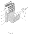
- the advantage of such an arrangement of the coupling unit 3 and such a cable routing is that a large number of flexible supply lines 17, as shown in FIG. 6, do not hinder the installation space for loom installations.
- Another advantage can be that the pressure medium acting on the decoupling device 11 is present externally, ie outside the weaving machine, and is only available for decoupling the heald frames when needed, for example when changing articles.
- connection 18 is a pressure medium connection in the case of a pneumatically or hydraulically actuated slide unit 13, 14 or an electrical connection in the case of an electromagnetic drive 12.
- FIG. 5 also shows a coupling unit 1 on the bumper side in the coupled state with a coupling unit 3 on the shaft side.
- the bumper 10 is articulated in a first articulation point 30a of a bell crank 30.
- the pull rod 31 connected to a shaft drive (not shown) is articulated in a second articulation point 30b.
- the bell crank 30 is pivotally mounted in a joint 30c about its central axis 30c '.
- Each of the articulation points 30a, 30b, 30c is formed by an axle which is the articulation point for a plurality of deflection levers 30, bumpers 10 and tie rods 31.
- FIG. 6 shows a large number of coupling units 3 with a decoupling device 11 arranged one behind the other on the bumper.
- Each decoupling device has a connecting piece 16 to which a pressure medium line 17 is connected.
- the pressure medium line 17 leads to a pressure medium storage or distributor 19 which is connected via a check valve 20 and line 21 to a pressure medium source p, not shown.
Abstract
Description
Die Erfindung betrifft eine Webschaftkupplung mit einer Vorrichtung zum Entkuppeln eines Webschaftes von Stoßstangen und ferner eine Webmaschine mit einer Vielzahl von Webschäften, die simultan von den Stoßstangen entkuppelbar ist.The invention relates to a heald frame coupling with a device for Uncoupling a heald frame from bumpers and also using a loom a variety of heald frames that can be uncoupled from the bumpers simultaneously is.
Bekannt ist aus der DE-PS 43 43 882 C1 eine Webschaftkupplung und eine
Vorrichtung zum simultanen Öffnen und Schließen einer Vielzahl solcher
Kupplungen in einer Webmaschine.
Derartige Webschaftkupplungen bestehen aus einer webschaftseitigen
Kupplungseinheit mit wenigstens einem ersten Kupplungselement und aus einer
stoßstangenseitigen Kupplungseinheit mit wenigstens einem zweiten
Kupplungselement, an welchem ein durch eine Zugfeder belasteter
Hebelmechanismus mit einem ein freies Ende aufweisenden Schwenkhebel
angreift.
Der Hebelmechanismus erlaubt ein Kuppeln der beiden Kupplungseinheiten und
unterbindet ein Entkuppeln dieser Einheiten.
Insbesondere zum Zwecke eines rationellen und effektiven Artikelwechsels werden
die Webschäfte in Art eines sogenannten Schäftepaketes aus der Webmaschine
gehoben bzw. in diese eingesetzt.
Dazu ist es erforderlich, die Webschaftkupplungen nicht nur so auszubilden, daß
ein simultanes Einsetzen der Webschäfte und Kuppeln mit den Stoßstangen
erfolgen kann, sondern in gleicher Weise ein Entkuppeln aller Webschäfte von den
Stoßstangen gegeben ist.From DE-PS 43 43 882 C1 a heald frame coupling and a device for the simultaneous opening and closing of a large number of such couplings in a weaving machine are known.
Such heald frame couplings consist of a heald frame side coupling unit with at least one first coupling element and a push rod side coupling unit with at least one second coupling element, on which a lever mechanism loaded by a tension spring engages with a pivot lever having a free end.
The lever mechanism allows the two coupling units to be coupled and prevents these units from being uncoupled.
In particular for the purpose of a rational and effective article change, the heald frames are lifted out of the weaving machine or inserted into them in the manner of a so-called shaft package.
For this purpose, it is necessary not only to design the heald frame couplings in such a way that the heald frames and domes can be inserted simultaneously with the bumpers, but in the same way that all heald frames are uncoupled from the bumpers.
Die DE-PS 43 43 882 C1 offenbart ferner eine Vorrichtung zum simultanen Öffnen
einer Vielzahl der in der vorgenannten Patentschrift beschriebenen
Webschaftkupplungen.
Eine solche Vorrichtung besteht aus einer drehangetriebenen Stellwelle, die sich
über die Gesamtzahl der Einzelschäfte quer zu deren Hubbewegung erstreckt. Auf
der Stellwelle ist jeder stoßstangenseitigen Kupplungseinheit ein Betätigungselement
zum Entkuppeln zugeordnet. Alle Betätigungselemente sind drehfest mit
der Stellwelle verbunden und können simultan mit dem Hebelmechanismus jeder
stoßstangenseitigen Kupplungseinheit in Wirkverbindung gebracht werden.DE-PS 43 43 882 C1 also discloses a device for the simultaneous opening of a plurality of the heald frame couplings described in the aforementioned patent specification.
Such a device consists of a rotationally driven actuating shaft which extends across the total number of individual shafts transversely to their lifting movement. An actuating element for uncoupling is assigned to each coupling unit on the bumper side on the adjusting shaft. All actuators are non-rotatably connected to the control shaft and can be simultaneously connected to the lever mechanism of each clutch unit on the bumper.
Eine solche Entkupplungsvorrichtung ist sowohl material- als auch fertigungstechnisch und montageseitig kostenaufwendig.Such a decoupling device is both material and manufacturing technology and costly on the assembly side.
Die Aufgabe der Erfindung ist es, für eine an sich bekannte Webschaftkupplung eine Entkupplungsvorrichtung zu schaffen, die gegenüber der bekannten Entkupplungsvorrichtung vergleichsweise, unter Aufrechterhaltung einer hohen Funktionssicherheit, kostengünstiger herstellbar und platzsparender ist.The object of the invention is for a heald frame coupling known per se to provide a decoupling device that compared to the known Uncoupling device comparatively, while maintaining a high Functional reliability, is cheaper to manufacture and space-saving.
Erfindungsgemäß wird die Aufgabe durch die Merkmale der unabhängigen Patentansprüche gelöst.According to the invention, the object is characterized by the features of the independent Claims resolved.
Die Erfindung soll nachstehend anhand der in den Zeichnungen beispielhaften
Darstellungen näher erläutert werden.
Es zeigen:
- Figur 1:
- eine geöffnet Kupplungseinheit mit der im Schnitt dargestellten druckmittelbetriebenen Entkupplungsvorrichtung, stoßstangenseitig angeordnet,
- Figur 2:
- eine geöffnet Kupplungseinheit mit der im Schnitt dargestellten elektromagnetisch betriebenen Entkupplungsvorrichtung, stoßstangenseitig angeordnet,
- Figur 3:
- die druckmittelbetriebene Entkupplungsvorrichtung als Schiebergehäuse mit Schieber,
- Figur 4:
- eine geöffnet Kupplungseinheit mit der im Schnitt dargestellten druckmittelbetriebenen Entkupplungsvorrichtung, schaftseitig angeordnet,
- Figur 5:
- einen Teil eines schematisch dargestellten Webschaftes mit dem Anschluß für die zur Entkupplungsvorrichtung führende Versorgungsleitung,
- Figur 6:
- die Vielzahl der stoßstangenseitigen Kupplungseinheiten mit integraler Entkupplungsvorrichtung in Verbindung mit einem Druckmittelverteiler,
Show it:
- Figure 1:
- an opened clutch unit with the pressure medium-operated decoupling device shown in section, arranged on the bumper side,
- Figure 2:
- an opened clutch unit with the electromagnetically operated decoupling device shown in section, arranged on the bumper side,
- Figure 3:
- the pressure medium-operated decoupling device as a slide housing with slide,
- Figure 4:
- an opened coupling unit with the pressure medium-operated decoupling device shown in section, arranged on the shaft side,
- Figure 5:
- part of a schematically illustrated heald frame with the connection for the supply line leading to the decoupling device,
- Figure 6:
- the large number of coupling units on the bumper side with an integral decoupling device in connection with a pressure medium distributor,
Jeder Webschaft einer Webmaschine verfügt bekanntlich zu seiner Betätigung
über schaftseitige Kupplungsmittel, die mit sogenannten stoßstangenseitigen
Kupplungseinheiten kuppelbar sind.
In Figur 1 ist von der schaftseitigen Kupplungseinheit 1 das Kupplungselement 2
als deren Hauptbestandteil dargestellt.
Das Kupplungselement 2 befindet sich außer Eingriff von der Kupplungseinheit 3.
Derartige Kupplungseinheiten sind aus der DE-PS 43 43 882 C1 prinzipiell
bekannt.
Nicht bekannt ist, eine Kupplungseinheit mit einer integrierten
Entkupplungsvorrichtung.Each heald frame of a weaving machine is known to have shaft-side coupling means for its actuation, which can be coupled with so-called bumper-side coupling units.
In Figure 1, the
The
What is not known is a coupling unit with an integrated decoupling device.
Gemäß Figur 1 und 3 besteht die Entkupplungsvorrichtung 11 aus einem
Schiebergehäuse 13 mit einem darin längs verschiebbaren Schieber 14, der eine
mit Druckmittel beaufschlagbare Schieberfläche 14a und eine der Schieberfläche
14a gegenüberliegende Schieberfläche 14b besitzt.
Die Schieberfläche 14a ist überwenigstens einen im Schiebergehäuse-Boden 13a
vorhandenen Einlaß 13c mit Druckmittel beaufschlagbar.
Auf der Schieberfläche 14b ruht das freie Ende des Schwenkhebels 7 der
Kupplungseinheit 3 mit der Spannkraft der Zugfeder 5.According to FIGS. 1 and 3, the
The
The free end of the
Schiebergehäuse 13 und Schieber 14 besitzen zum Eingriff des Hebelarms von
Schwenkhebel 7 in die Entkupplungsvorrichtung 11 eine Aussparung 13b bzw.
14c. Diese Aussparungen dienen gleichzeitig der Seitenführung des
Schwenkhebels 7.
Die Entkupplungsvorrichtung 11 besteht, wie in Figur 1 zu erkennen, z.B. aus dem
Schiebergehäuse-Boden 13a und aus dem eigentlichen Schieber-Gehäuse 13, in
dem der Schieber 14 aufgenommen ist.
Zum Beispiel über nur andeutungsweise dargestellte Gewindebohrungen 28, die in
einem Ansatz 13a' des Schiebergehäuse-Bodens 13a eingebracht sind, ist die
Entkupplungsvorrichtung 11 mit der Kupplungseinheit 3 schraubverbunden.
Wichtig bei der Positionierung und Montage der Entkupplungsvorrichtung 11 in der
Kupplungseinheit 3 ist, daß zwischen dem Gehäuse 13 der Entkupplungsvorrichtung
11 und dem Hebelmechanismus 6 ausreichend Raum für die
Auslenkung des Schwenkhebels 7 innerhalb der Kupplungseinheit 3 besteht.
As can be seen in FIG. 1, the
For example, the threaded
It is important when positioning and assembling the
Die Funktionsweise der Webschaftkupplung mit Entkupplungsvorrichtung ist wie folgt:The mode of operation of the heald frame coupling with decoupling device is like follows:
Wird von den gemäß Figur 6 dargestellten Mitteln 19, 20, 21 ein Druckmittel über
die Versorgungsleitung 17, Anschlußstück 16 und Einlaß 13c auf die
Schieberfläche 14a geleitet, schiebt der Schieber 14 den Schwenkhebel 7 derart in
Richtung Öffnung des Schiebergehäuses 13, daß sich dieser um seine Drehachse
7a schwenkt. Das andere freie Ende des Schwenkhebels 7, welches in einer
gemeinsamen Gelenkstelle 6a für den Hebel 29 und die Zugfeder 5 angelenkt ist,
bringt die Gelenkstelle 6a in die gestrichelt dargestellte Position. Durch diese
Schwenkbewegung wird das Kupplungselement 4 um die Achse 4a in
Entkuppelposition geschwenkt.
In der hier dargestellten Position befindet sich das Kupplungselement 4 bereits
wieder in der Kuppelstellung, wobei sich die Kupplungselemente 4 und 2 außer
Eingriff befinden. Das bedeutet, die betreffenden, jedoch nicht dargestellten
Webschäfte, sind z.B. zum Zwecke eines Artikelwechsels von ihrem Antrieb gelöst.
Der Kuppelvorgang erfolgt in umgekehrter Weise, allerdings ohne Druckmittelbeaufschlagung
der Entkupplungsvorrichtung 11.
In diesem Fall wirkt der federbelastete Hebelmechanismus 6 mit Kupplungselement
4 als Schnappverschluß für das Kupplungselement 2.If from the
In the position shown here, the
In this case, the spring-loaded
In Figur 2 ist die Entkupplungsvorrichtung 11 als elektromagnetischer Antrieb 12
für den Schwenkhebel 7 ausgebildet. Das freie Ende des Schwenkhebels 7 liegt an
der vorderen Endfläche eines in einer mittels Elektroenergie erregbaren Spule 12a
verschiebbaren Magnetkerns 12b.
Durch eine Hubbewegung des Magnetkerns 12b ist der Schwenkhebel 7 in die
gestrichelt dargestellte Position bewegbar, womit ein Entkuppeln der
Kupplungselemente 2 und 4 erreicht wird.
In der Darstellung gemäß Figur 2 ist die Magnetspule nicht erregt.In Figure 2, the
The
In the illustration according to FIG. 2, the magnetic coil is not excited.
In Figur 4 wird die stoßstangenseitige Kupplungseinheit 3 gemäß der Figuren 1
und 2 als schaftseitige Kupplungseinheit verwendet.
Die Kupplungseinheit 3 mit der Entkupplungsvorrichtung 11 ist hier mittels
Schrauben 22 mit dem Schaftstab 15a eines Webschaftes 15 verbunden.
Die zum Anschlußstück 16 führende Versorgungsleitung 17 ist durch die jeweilige
rechte und/oder linke Seitenstütze 15a des jeweiligen Webschaftes 15 geführt.
Der Anfang der Versorgungsleitung ist mit einem Druckmittelanschluß 18, der am
oberen freien Ende der Seitenstütze 15b angeordnet ist, verbunden; siehe auch
Figur 5.In FIG. 4, the
The
The
Der Vorteil einer solchen Anordnung der Kupplungseinheit 3 und einer solchen
Leitungsführung besteht darin, daß nicht eine Vielzahl von flexiblen
Versorgungsleitungen 17, wie in Figur 6 dargestellt, den Bauraum für
Webmaschineneinbauten behindert.
Ein weiterer Vorteil kann darin bestehen, daß das die Entkupplungsvorrichtung 11
beaufschlagende Druckmedium extern, d.h. außerhalb der Webmaschine vorliegt
und nur bei Bedarf, also z.B. bei Artikelwechsel, zum Entkuppeln der Webschäfte
zur Verfügung steht. The advantage of such an arrangement of the
Another advantage can be that the pressure medium acting on the
Erfindungswesentlich nach Figur 5 ist, daß die Versorgungsleitung 17, ausgehend
von der Entkupplungsvorrichtung 11, durch die Seitenstütze 15b des Webschaftes
15 geführt ist und in einem Anschluß 18 mündet.
Der Anschluß 18 ist im Falle einer pneumatisch oder hydraulisch beaufschlagten
Schiebereinheit 13, 14 ein Druckmittelanschluß oder im Falle der Ausbildung als
elektromagnetischer Antrieb 12 ein Elektroanschluß.It is essential to the invention according to FIG. 5 that the
The
Figur 5 zeigt ferner eine stoßstangenseitige Kupplungseinheit 1 in gekuppeltem
Zustand mit einer schaftseitigen Kupplungseinheit 3.
Die Stoßstange 10 ist in einer ersten Gelenkstelle 30a eines Umlenkhebels 30
angelenkt. In einer zweiten Gelenkstelle 30b ist die mit einem nicht dargestellten
Schaftantrieb verbundene Zugstange 31 angelenkt.
Der Umlenkhebel 30 ist in einer Gelenktstelle 30c schwenkbar um deren
Mittenachse 30c' gelagert.
Jede der Gelenktstellen 30a, 30b, 30c wird von einer Achse gebildet, die die
Gelenkstelle für eine Vielzahl von Umlenkhebeln 30, Stoßstangen 10 und
Zugstangen 31 ist.FIG. 5 also shows a
The
The
Each of the
Figur 6 zeigt eine Vielzahl hintereinander angeordneter stoßstangenseitiger
Kupplungseinheiten 3 mit Entkupplungsvorrichtung 11. Jede Entkupplungsvorrichtung
weist ein Anschlußstück 16 auf, an das eine Druckmittelleitung 17
angeschlossen ist.
Die Druckmittelleitung 17 führt zu einem Druckmittelspeicher oder -verteiler 19, der
über ein Sperrventil 20 und Leitung 21 an eine nicht dargestellte Druckmittelquelle
p angeschlossen ist. FIG. 6 shows a large number of
The
- 0101
- Kupplungseinheit, schaftseitigCoupling unit, on the shaft side
- 0202
- Kupplungselementcoupling member
- 0303
- Kupplungseinheit, stoßstangenseitigCoupling unit, on the bumper side
- 0404
- Kupplungselementcoupling member
- 04a04a
- Achseaxis
- 0505
- Zugfedermainspring
- 0606
- Hebelmechanismuslever mechanism
- 06a06a
- Gelenkstellearticulation point
- 0707
- Schwenkhebelpivoting lever
- 07a07a
- Drehachseaxis of rotation
- 0808
- Lagerplatte, vordereFront bearing plate
- 0909
- Lagerplatte, hintereBearing plate, rear
- 1010
- Stoßstangebumper
- 1111
- EntkupplungsvorrichtungUncoupling
- 1212
- Antriebdrive
- 12a12a
- SpuleKitchen sink
- 12b12b
- Magnetkernmagnetic core
- 1313
- Schiebergehäuseslide housing
- 13a13a
- Schiebergehäuse-BodenSlide housing bottom
- 13a'13a '
- Ansatzapproach
- 13b13b
- Aussparungrecess
- 13c13c
- EinlaßInlet
- 1414
- Schieberpusher
- 14a14a
- Schieberflächegate surface
- 14b14b
- Schieberflächegate surface
- 14c14c
- Aussparungrecess
- 1515
- Webschaftheald
- 15a15a
- Schaftstab stave
- 15b15b
- Seitenstützeside support
- 1616
- Anschlußstückconnector
- 1717
- Versorgungsleitungsupply line
- 1818
- AnschlußConnection
- 1919
- Druckmittelspeicher/-verteilerAccumulator / Distributor
- 2020
- Sperrventilcheck valve
- 2121
- Leitungmanagement
- 2222
- Schraubescrew
- 2828
- Gewindebohrungthreaded hole
- 3030
- UmlenkhebelUmlenkhebel
- 30a30a
- Gelenkstellearticulation point
- 30b30b
- Gelenkstellearticulation point
- 30c30c
- Gelenkstellearticulation point
- 30c'30c '
- Mittenachsemid-axis
- 3131
- Zugstangepull bar
- pp
- DruckmittelquellePressure medium source
Claims (11)
- Heald frame coupling having a device for disengaging a heald frame from push rods, comprising a heald frame-side coupling unit (1) having at least one first coupling element (2) and a push rod-side coupling unit (3) having at least one second coupling element (4) on which acts a lever mechanism (6) loaded by a tension spring (5) and having a pivoted lever (7) with a free end, which lever mechanism (6) allows engagement of the two coupling units (1, 3) and prevents disengagement and wherein the push rod-side coupling element (4) and the lever mechanism (6) are arranged between a front bearing plate (8) and a rear bearing plate (9) and are supported thereby and wherein furthermore the bearing plates (8, 9) are connected congruently with the push rod (10), characterised in that the disengagement is effected by means of a disengagement device (11) integral with the push rod-side coupling unit, mounted close to the lever mechanism (6) and acted upon by a pneumatic or hydraulic pressure medium, the disengagement device being in operative connection with the lever mechanism (6).
- A heald frame coupling having a device for disengaging a heald frame from push rods, comprising a heald frame-side coupling unit (1) having at least one first coupling element (2) and a push rod-side coupling unit (3) having at least one second coupling element (4) on which acts a lever mechanism (6) loaded by a tension spring (5) and having a pivoted lever (7) with a free end, which lever mechanism (6) allows engagement of the two coupling units (1, 3) and prevents disengagement and wherein the push rod-side coupling element (4) and the lever mechanism (6) are arranged between a front bearing plate (8) and a rear bearing plate (9) and are supported thereby, and wherein furthermore the bearing plates (8, 9) are connected congruently with the push rod (10), characterised in that the disengagement is effected by means of a disengagement device (11) in the form of an electromagnetic drive (12) integral with the push-rod side coupling unit, the electromagnetic drive (12) being operatively connected with the lever mechanism (6).
- A heald frame coupling according to claim 2, characterised in that the electromagnetic drive (12) is a solenoid actuator.
- A heald frame coupling according to claim 1, characterised in that the disengagement device (11) consists of a slider housing (13) with a single-acting slider (14) guided therein, the slider having a slider face (14a) on which a pressure medium acts and, opposing the slider face (14a), a slider face (14b) on which the free end of a pivoted lever (7) rests with the translated force of the tension spring (5).
- A heald frame coupling according to claim 4, characterised in that the slider housing (13) forms a rectangular guide for the slider (14), in that the travel of the slider (14) is limited on the one side by the inside of the slider housing base (13a) and on the other side by the magnitude of a pivoting angle α of the pivoting lever (7) resting on the outer slider face (14b) and in that, for connection of the slider housing (13) with the push rod-side coupling unit (3), the base (13a) of the slider housing (13) has at least one outer projection (13a').
- A heald frame coupling according to claims 4 and 5, characterised in that both the slider housing (13) and the slider (14) have a slot-like recess (13b, 14c respectively) in which the pivoted lever (7) is laterally guided.
- A loom having a plurality of heald frames which are arranged to be connected with push rods by way of heald frame couplings (1) according to one of the preceding claims, wherein each disengagement device comprises a connection connectible with a supply line, and wherein the heald frames consist of heald frame rods and side supports, characterised in that the push rod-side coupling unit (3), which has a pressure medium-operated or electromagnetically operated disengagement device (11), functions as frame-side coupling unit and the frame-side coupling unit (1) functions as push-rod side coupling unit, wherein parts of each heald frame receive the supply line (17) of the disengagement device (11) or, when the supply line is in the form of a pressure line, themselves form a supply line (17).
- A loom according to claim 7, characterised in that the parts of each heald frame are the side supports (15b) and/or at least one of the heald frame rods (15a).
- A loom according to claim 7, characterised in that, in the case of a pressure medium-operated disengagement device (11), each heald frame (15) has at least one pressure medium connection (18) for connection with a pressure medium source.
- A loom according to claim 7, characterised in that, in the case of an electromagnetically operated disengagement device (11), each heald frame (15) has at least one supply connection for a power cable for connection to a source of electricity.
- A loom having a plurality of heald frames that are arranged to be connected with push rods by way of heald frame couplings comprising coupling units, characterised in that each push rod-side coupling unit has an integrated disengagement device, which has a pressure medium connection provided with a supply line, and each supply line (17) is connected to a common pressure accumulator (19) that is in connection by way of a controllable shut-off valve (20) with a pressure medium source (p).
Applications Claiming Priority (2)
| Application Number | Priority Date | Filing Date | Title |
|---|---|---|---|
| DE19548848 | 1995-12-27 | ||
| DE19548848A DE19548848C1 (en) | 1995-12-27 | 1995-12-27 | Loom shaft uncoupling unit |
Publications (3)
| Publication Number | Publication Date |
|---|---|
| EP0784111A2 EP0784111A2 (en) | 1997-07-16 |
| EP0784111A3 EP0784111A3 (en) | 1998-02-11 |
| EP0784111B1 true EP0784111B1 (en) | 2002-10-02 |
Family
ID=7781499
Family Applications (1)
| Application Number | Title | Priority Date | Filing Date |
|---|---|---|---|
| EP19960118558 Expired - Lifetime EP0784111B1 (en) | 1995-12-27 | 1996-11-20 | Shaft coupling element with unlocking mechanism |
Country Status (5)
| Country | Link |
|---|---|
| US (1) | US5810055A (en) |
| EP (1) | EP0784111B1 (en) |
| JP (2) | JP3140386B2 (en) |
| AT (1) | ATE225419T1 (en) |
| DE (2) | DE19548848C1 (en) |
Families Citing this family (14)
| Publication number | Priority date | Publication date | Assignee | Title |
|---|---|---|---|---|
| DE19640370C1 (en) * | 1996-09-30 | 1998-02-12 | Dornier Gmbh Lindauer | Assemblies to hold and guide loom shaft rods |
| FR2815047B1 (en) * | 2000-10-06 | 2003-02-07 | Staubli Sa Ets | HANGING DEVICE BETWEEN A STRING FRAME AND A LEVER AND WEAVING MACHINE INCORPORATING SUCH A DEVICE |
| DE10111017B4 (en) * | 2001-03-07 | 2006-02-02 | Lindauer Dornier Gmbh | Drive for the heald frames of a loom |
| US7131672B2 (en) * | 2002-05-03 | 2006-11-07 | Hartwell Corporation | Latch mechanism |
| JP3994897B2 (en) * | 2003-03-18 | 2007-10-24 | 株式会社豊田自動織機 | Opening device in loom |
| JP2007009606A (en) * | 2005-07-01 | 2007-01-18 | Muroto Tekkosho:Kk | Safety device for attachment fastening device of power shovel |
| US20080053555A1 (en) * | 2006-07-19 | 2008-03-06 | Groz-Beckert Kg | Shaft drive transmission and coupling rod |
| EP1992724B1 (en) * | 2007-05-14 | 2012-01-25 | Groz-Beckert KG | Heald shaft divisible in two |
| EP2009157B1 (en) * | 2007-06-26 | 2010-01-06 | Groz-Beckert KG | Frame connection device for a heald frame |
| DE102008035928A1 (en) * | 2008-08-01 | 2010-02-04 | Assa Abloy Sicherheitstechnik Gmbh | Door opener with remote-controlled valve |
| EP2573240B1 (en) * | 2011-09-20 | 2015-05-27 | Groz-Beckert KG | High speed safety heald shaft |
| EP2998421B1 (en) | 2014-09-16 | 2020-04-08 | Groz-Beckert KG | Heald frame coupling and heald frame with the same |
| ITUB20155435A1 (en) * | 2015-11-10 | 2016-02-10 | Itema Spa | Quick coupling system for square-healds in a weaving loom |
| FR3121152B1 (en) * | 2021-03-24 | 2024-05-03 | Staubli Faverges | Pulling mechanism for controlling heddle frames of a loom and loom comprising such a mechanism |
Family Cites Families (15)
| Publication number | Priority date | Publication date | Assignee | Title |
|---|---|---|---|---|
| DE2933699C3 (en) * | 1979-08-21 | 1982-02-25 | Lindauer Dornier Gmbh, 8990 Lindau | Hitching device for the heald hoist on the heald frame |
| CH639706A5 (en) * | 1979-09-28 | 1983-11-30 | Rueti Ag Maschf | DEVICE FOR COUPLING AN EXTENSION WITH A WEBSHAFT FRAME. |
| FR2540898A1 (en) * | 1983-02-16 | 1984-08-17 | Staubli Sa Ets | HANGING DEVICE FOR THE SEMI-AUTOMATIC LINKAGE OF HARNESSES OF WEAVING MATERIALS WITH LEVERS INTENDED FOR THEIR CONTROL |
| DE3541042C1 (en) * | 1985-11-19 | 1987-01-29 | Grob & Co Ag | Device for coupling a heald frame with a drive element |
| EP0279874B1 (en) * | 1987-02-21 | 1990-05-16 | Dr.-Ing. Rudolf Hell GmbH | Picture drum clamping device |
| NO178181C (en) * | 1988-06-27 | 1996-02-07 | Kvaerner Brug As | Sealing device for flexible tensioning joints in a tensioning platform platform leg |
| CH681374A5 (en) * | 1989-07-07 | 1993-03-15 | Sulzer Ag | |
| IT1252301B (en) * | 1991-11-15 | 1995-06-08 | Nuovo Pignone Spa | AUTOMATIC CONTROL SYSTEM FOR ELECTRONIC ROTARY DOBBY |
| DE59206671D1 (en) * | 1992-11-13 | 1996-08-01 | Rueti Ag Maschf | Device for coupling and uncoupling heald frames and loom with such a device |
| EP0598161A1 (en) * | 1992-11-13 | 1994-05-25 | Sulzer RàTi Ag | Loom with automatic heald-locks |
| DE59208467D1 (en) * | 1992-11-13 | 1997-06-12 | Rueti Ag Maschf | Device for receiving shaft rods and weaving machine with such a device |
| EP0598167A1 (en) * | 1992-11-17 | 1994-05-25 | Sulzer RàTi Ag | Coupling device for a heald frame and loom with coupling device |
| EP0654552A1 (en) * | 1993-11-24 | 1995-05-24 | Sulzer RàTi Ag | Heddle frames connection device and loom with such a device |
| DE4343882C1 (en) * | 1993-12-22 | 1995-01-19 | Dornier Gmbh Lindauer | Heald-frame coupling and device for the simultaneous opening and closing of a plurality of heald-frame couplings in a weaving machine |
| JPH0941239A (en) * | 1995-07-25 | 1997-02-10 | Toyota Autom Loom Works Ltd | Attaching and detaching apparatus of heald frame and attachment and detachment therefor |
-
1995
- 1995-12-27 DE DE19548848A patent/DE19548848C1/en not_active Expired - Fee Related
-
1996
- 1996-11-20 EP EP19960118558 patent/EP0784111B1/en not_active Expired - Lifetime
- 1996-11-20 AT AT96118558T patent/ATE225419T1/en not_active IP Right Cessation
- 1996-11-20 DE DE59609750T patent/DE59609750D1/en not_active Expired - Lifetime
- 1996-12-23 US US08/780,056 patent/US5810055A/en not_active Expired - Lifetime
- 1996-12-25 JP JP34609996A patent/JP3140386B2/en not_active Expired - Fee Related
-
2000
- 2000-10-16 JP JP2000314815A patent/JP3544934B2/en not_active Expired - Fee Related
Also Published As
| Publication number | Publication date |
|---|---|
| DE59609750D1 (en) | 2002-11-07 |
| JP3140386B2 (en) | 2001-03-05 |
| DE19548848C1 (en) | 1996-09-12 |
| JP3544934B2 (en) | 2004-07-21 |
| JPH09209242A (en) | 1997-08-12 |
| EP0784111A2 (en) | 1997-07-16 |
| US5810055A (en) | 1998-09-22 |
| JP2001140139A (en) | 2001-05-22 |
| ATE225419T1 (en) | 2002-10-15 |
| EP0784111A3 (en) | 1998-02-11 |
Similar Documents
| Publication | Publication Date | Title |
|---|---|---|
| EP0784111B1 (en) | Shaft coupling element with unlocking mechanism | |
| DE102007028151A1 (en) | Injection molding apparatus e.g. valve pin actuating apparatus for hot runner apparatus, has yoke plate connected to actuator assembly which moves yoke plate in direction parallel to longitudinal axis of valve pins of nozzles | |
| EP0659916B1 (en) | Shaft coupling element and device for the simultaneous opening and closing a plurality of shaft coupling elements in a loom | |
| EP0555857A2 (en) | Rear wheel steering | |
| AT394118B (en) | DEVICE FOR INTERLOCKING THE MOVABLE PARTS AT LEAST TWO ELECTROMAGNETICALLY CONTROLLED ELECTRICAL SWITCHING DEVICES AND ELECTRICAL SYSTEM WITH SUCH A DEVICE | |
| DE102014209138A1 (en) | Locking element for an injection molding machine | |
| DE60217851T3 (en) | THREAD CLAMP FOR A WEAVING MACHINE AND WEB MACHINE WITH SUCH A THREAD CLAMP | |
| DE4138297C2 (en) | Toggle mold locking system for a vertical injection molding machine | |
| DE102020122839A1 (en) | Switchable magnet device | |
| DE102009046213B4 (en) | Removable frame for a front loader | |
| DE102008014488A1 (en) | Door lock for building, has electromagnet arranged in lock case at assembly position such that electromagnet transfers connecting lever in locking or lifting positions in powered or non-powered conditions | |
| EP1638117B1 (en) | Electromagnetic actuator | |
| DE4444823C2 (en) | Warp knitting machine with individually movable thread guides attached to a bar | |
| DE19650928A1 (en) | Door lock for vehicle | |
| DE3051183C2 (en) | Device for the control or monitoring of machines | |
| EP0654552A1 (en) | Heddle frames connection device and loom with such a device | |
| DE102019002643B3 (en) | Device for locking and unlocking a latch tower | |
| EP1564466B1 (en) | Multiple way double seat valve with magnet actuation | |
| DE19636315C2 (en) | Münzauszahlvorrichtung | |
| EP4183658A1 (en) | Device for blending or printing. unlocking of a coupling of a rail vehicle | |
| EP0281109B1 (en) | Writing device including a writing head arrangement and a platen | |
| DE3631104A1 (en) | Safety circuit, in particular for a press | |
| DE2247993C3 (en) | Standardized module component for a pneumatic control device | |
| DE19548847C1 (en) | Loom shaft assembly | |
| WO2005028723A2 (en) | Coupling method for textile technology |
Legal Events
| Date | Code | Title | Description |
|---|---|---|---|
| PUAI | Public reference made under article 153(3) epc to a published international application that has entered the european phase |
Free format text: ORIGINAL CODE: 0009012 |
|
| AK | Designated contracting states |
Kind code of ref document: A2 Designated state(s): AT BE CH DE DK ES FI FR GB GR IE IT LI LU MC NL PT SE |
|
| PUAL | Search report despatched |
Free format text: ORIGINAL CODE: 0009013 |
|
| AK | Designated contracting states |
Kind code of ref document: A3 Designated state(s): AT BE CH DE DK ES FI FR GB GR IE IT LI LU MC NL PT SE |
|
| 17P | Request for examination filed |
Effective date: 19980714 |
|
| 17Q | First examination report despatched |
Effective date: 20001219 |
|
| GRAG | Despatch of communication of intention to grant |
Free format text: ORIGINAL CODE: EPIDOS AGRA |
|
| GRAG | Despatch of communication of intention to grant |
Free format text: ORIGINAL CODE: EPIDOS AGRA |
|
| GRAH | Despatch of communication of intention to grant a patent |
Free format text: ORIGINAL CODE: EPIDOS IGRA |
|
| GRAH | Despatch of communication of intention to grant a patent |
Free format text: ORIGINAL CODE: EPIDOS IGRA |
|
| GRAA | (expected) grant |
Free format text: ORIGINAL CODE: 0009210 |
|
| AK | Designated contracting states |
Kind code of ref document: B1 Designated state(s): AT BE CH DE DK ES FI FR GB GR IE IT LI LU MC NL PT SE |
|
| PG25 | Lapsed in a contracting state [announced via postgrant information from national office to epo] |
Ref country code: NL Free format text: LAPSE BECAUSE OF FAILURE TO SUBMIT A TRANSLATION OF THE DESCRIPTION OR TO PAY THE FEE WITHIN THE PRESCRIBED TIME-LIMIT Effective date: 20021002 Ref country code: IE Free format text: LAPSE BECAUSE OF FAILURE TO SUBMIT A TRANSLATION OF THE DESCRIPTION OR TO PAY THE FEE WITHIN THE PRESCRIBED TIME-LIMIT Effective date: 20021002 Ref country code: GR Free format text: LAPSE BECAUSE OF FAILURE TO SUBMIT A TRANSLATION OF THE DESCRIPTION OR TO PAY THE FEE WITHIN THE PRESCRIBED TIME-LIMIT Effective date: 20021002 Ref country code: FI Free format text: LAPSE BECAUSE OF FAILURE TO SUBMIT A TRANSLATION OF THE DESCRIPTION OR TO PAY THE FEE WITHIN THE PRESCRIBED TIME-LIMIT Effective date: 20021002 |
|
| REF | Corresponds to: |
Ref document number: 225419 Country of ref document: AT Date of ref document: 20021015 Kind code of ref document: T |
|
| REG | Reference to a national code |
Ref country code: GB Ref legal event code: FG4D Free format text: NOT ENGLISH |
|
| REG | Reference to a national code |
Ref country code: CH Ref legal event code: EP |
|
| REG | Reference to a national code |
Ref country code: IE Ref legal event code: FG4D Free format text: GERMAN |
|
| REF | Corresponds to: |
Ref document number: 59609750 Country of ref document: DE Date of ref document: 20021107 |
|
| PG25 | Lapsed in a contracting state [announced via postgrant information from national office to epo] |
Ref country code: LU Free format text: LAPSE BECAUSE OF NON-PAYMENT OF DUE FEES Effective date: 20021120 Ref country code: AT Free format text: LAPSE BECAUSE OF NON-PAYMENT OF DUE FEES Effective date: 20021120 |
|
| REG | Reference to a national code |
Ref country code: CH Ref legal event code: NV Representative=s name: R. A. EGLI & CO. PATENTANWAELTE |
|
| PG25 | Lapsed in a contracting state [announced via postgrant information from national office to epo] |
Ref country code: SE Free format text: LAPSE BECAUSE OF FAILURE TO SUBMIT A TRANSLATION OF THE DESCRIPTION OR TO PAY THE FEE WITHIN THE PRESCRIBED TIME-LIMIT Effective date: 20030102 Ref country code: PT Free format text: LAPSE BECAUSE OF FAILURE TO SUBMIT A TRANSLATION OF THE DESCRIPTION OR TO PAY THE FEE WITHIN THE PRESCRIBED TIME-LIMIT Effective date: 20030102 Ref country code: DK Free format text: LAPSE BECAUSE OF FAILURE TO SUBMIT A TRANSLATION OF THE DESCRIPTION OR TO PAY THE FEE WITHIN THE PRESCRIBED TIME-LIMIT Effective date: 20030102 |
|
| GBT | Gb: translation of ep patent filed (gb section 77(6)(a)/1977) |
Effective date: 20030127 |
|
| NLV1 | Nl: lapsed or annulled due to failure to fulfill the requirements of art. 29p and 29m of the patents act | ||
| ET | Fr: translation filed | ||
| PG25 | Lapsed in a contracting state [announced via postgrant information from national office to epo] |
Ref country code: ES Free format text: LAPSE BECAUSE OF FAILURE TO SUBMIT A TRANSLATION OF THE DESCRIPTION OR TO PAY THE FEE WITHIN THE PRESCRIBED TIME-LIMIT Effective date: 20030429 |
|
| PG25 | Lapsed in a contracting state [announced via postgrant information from national office to epo] |
Ref country code: MC Free format text: LAPSE BECAUSE OF NON-PAYMENT OF DUE FEES Effective date: 20030601 |
|
| REG | Reference to a national code |
Ref country code: IE Ref legal event code: FD4D Ref document number: 0784111E Country of ref document: IE |
|
| PLBE | No opposition filed within time limit |
Free format text: ORIGINAL CODE: 0009261 |
|
| STAA | Information on the status of an ep patent application or granted ep patent |
Free format text: STATUS: NO OPPOSITION FILED WITHIN TIME LIMIT |
|
| 26N | No opposition filed |
Effective date: 20030703 |
|
| PGFP | Annual fee paid to national office [announced via postgrant information from national office to epo] |
Ref country code: GB Payment date: 20051028 Year of fee payment: 10 |
|
| GBPC | Gb: european patent ceased through non-payment of renewal fee |
Effective date: 20061120 |
|
| PG25 | Lapsed in a contracting state [announced via postgrant information from national office to epo] |
Ref country code: GB Free format text: LAPSE BECAUSE OF NON-PAYMENT OF DUE FEES Effective date: 20061120 |
|
| PGFP | Annual fee paid to national office [announced via postgrant information from national office to epo] |
Ref country code: CH Payment date: 20141120 Year of fee payment: 19 Ref country code: DE Payment date: 20141120 Year of fee payment: 19 |
|
| PGFP | Annual fee paid to national office [announced via postgrant information from national office to epo] |
Ref country code: FR Payment date: 20141118 Year of fee payment: 19 |
|
| PGFP | Annual fee paid to national office [announced via postgrant information from national office to epo] |
Ref country code: IT Payment date: 20141125 Year of fee payment: 19 |
|
| PGFP | Annual fee paid to national office [announced via postgrant information from national office to epo] |
Ref country code: BE Payment date: 20141125 Year of fee payment: 19 |
|
| REG | Reference to a national code |
Ref country code: DE Ref legal event code: R119 Ref document number: 59609750 Country of ref document: DE |
|
| REG | Reference to a national code |
Ref country code: CH Ref legal event code: PL |
|
| PG25 | Lapsed in a contracting state [announced via postgrant information from national office to epo] |
Ref country code: IT Free format text: LAPSE BECAUSE OF NON-PAYMENT OF DUE FEES Effective date: 20151120 Ref country code: LI Free format text: LAPSE BECAUSE OF NON-PAYMENT OF DUE FEES Effective date: 20151130 Ref country code: CH Free format text: LAPSE BECAUSE OF NON-PAYMENT OF DUE FEES Effective date: 20151130 |
|
| REG | Reference to a national code |
Ref country code: FR Ref legal event code: ST Effective date: 20160729 |
|
| PG25 | Lapsed in a contracting state [announced via postgrant information from national office to epo] |
Ref country code: DE Free format text: LAPSE BECAUSE OF NON-PAYMENT OF DUE FEES Effective date: 20160601 |
|
| PG25 | Lapsed in a contracting state [announced via postgrant information from national office to epo] |
Ref country code: FR Free format text: LAPSE BECAUSE OF NON-PAYMENT OF DUE FEES Effective date: 20151130 |
|
| PG25 | Lapsed in a contracting state [announced via postgrant information from national office to epo] |
Ref country code: BE Free format text: LAPSE BECAUSE OF NON-PAYMENT OF DUE FEES Effective date: 20151130 |