EP0783145A1 - Verbesserungen von oder bei Zählern - Google Patents
Verbesserungen von oder bei Zählern Download PDFInfo
- Publication number
- EP0783145A1 EP0783145A1 EP96119340A EP96119340A EP0783145A1 EP 0783145 A1 EP0783145 A1 EP 0783145A1 EP 96119340 A EP96119340 A EP 96119340A EP 96119340 A EP96119340 A EP 96119340A EP 0783145 A1 EP0783145 A1 EP 0783145A1
- Authority
- EP
- European Patent Office
- Prior art keywords
- chamber
- diaphragm
- valve
- gas
- meter
- Prior art date
- Legal status (The legal status is an assumption and is not a legal conclusion. Google has not performed a legal analysis and makes no representation as to the accuracy of the status listed.)
- Granted
Links
Images
Classifications
-
- G—PHYSICS
- G05—CONTROLLING; REGULATING
- G05D—SYSTEMS FOR CONTROLLING OR REGULATING NON-ELECTRIC VARIABLES
- G05D16/00—Control of fluid pressure
- G05D16/04—Control of fluid pressure without auxiliary power
- G05D16/06—Control of fluid pressure without auxiliary power the sensing element being a flexible membrane, yielding to pressure, e.g. diaphragm, bellows, capsule
- G05D16/063—Control of fluid pressure without auxiliary power the sensing element being a flexible membrane, yielding to pressure, e.g. diaphragm, bellows, capsule the sensing element being a membrane
- G05D16/0644—Control of fluid pressure without auxiliary power the sensing element being a flexible membrane, yielding to pressure, e.g. diaphragm, bellows, capsule the sensing element being a membrane the membrane acting directly on the obturator
- G05D16/0672—Control of fluid pressure without auxiliary power the sensing element being a flexible membrane, yielding to pressure, e.g. diaphragm, bellows, capsule the sensing element being a membrane the membrane acting directly on the obturator using several spring-loaded membranes
-
- Y—GENERAL TAGGING OF NEW TECHNOLOGICAL DEVELOPMENTS; GENERAL TAGGING OF CROSS-SECTIONAL TECHNOLOGIES SPANNING OVER SEVERAL SECTIONS OF THE IPC; TECHNICAL SUBJECTS COVERED BY FORMER USPC CROSS-REFERENCE ART COLLECTIONS [XRACs] AND DIGESTS
- Y10—TECHNICAL SUBJECTS COVERED BY FORMER USPC
- Y10T—TECHNICAL SUBJECTS COVERED BY FORMER US CLASSIFICATION
- Y10T137/00—Fluid handling
- Y10T137/7722—Line condition change responsive valves
- Y10T137/7781—With separate connected fluid reactor surface
- Y10T137/7793—With opening bias [e.g., pressure regulator]
- Y10T137/7796—Senses inlet pressure
-
- Y—GENERAL TAGGING OF NEW TECHNOLOGICAL DEVELOPMENTS; GENERAL TAGGING OF CROSS-SECTIONAL TECHNOLOGIES SPANNING OVER SEVERAL SECTIONS OF THE IPC; TECHNICAL SUBJECTS COVERED BY FORMER USPC CROSS-REFERENCE ART COLLECTIONS [XRACs] AND DIGESTS
- Y10—TECHNICAL SUBJECTS COVERED BY FORMER USPC
- Y10T—TECHNICAL SUBJECTS COVERED BY FORMER US CLASSIFICATION
- Y10T137/00—Fluid handling
- Y10T137/7722—Line condition change responsive valves
- Y10T137/7781—With separate connected fluid reactor surface
- Y10T137/7793—With opening bias [e.g., pressure regulator]
- Y10T137/7801—Balanced valve
-
- Y—GENERAL TAGGING OF NEW TECHNOLOGICAL DEVELOPMENTS; GENERAL TAGGING OF CROSS-SECTIONAL TECHNOLOGIES SPANNING OVER SEVERAL SECTIONS OF THE IPC; TECHNICAL SUBJECTS COVERED BY FORMER USPC CROSS-REFERENCE ART COLLECTIONS [XRACs] AND DIGESTS
- Y10—TECHNICAL SUBJECTS COVERED BY FORMER USPC
- Y10T—TECHNICAL SUBJECTS COVERED BY FORMER US CLASSIFICATION
- Y10T137/00—Fluid handling
- Y10T137/7722—Line condition change responsive valves
- Y10T137/7781—With separate connected fluid reactor surface
- Y10T137/7793—With opening bias [e.g., pressure regulator]
- Y10T137/7809—Reactor surface separated by apertured partition
- Y10T137/7812—Valve stem passes through the aperture
- Y10T137/7813—Plural reactor surfaces
-
- Y—GENERAL TAGGING OF NEW TECHNOLOGICAL DEVELOPMENTS; GENERAL TAGGING OF CROSS-SECTIONAL TECHNOLOGIES SPANNING OVER SEVERAL SECTIONS OF THE IPC; TECHNICAL SUBJECTS COVERED BY FORMER USPC CROSS-REFERENCE ART COLLECTIONS [XRACs] AND DIGESTS
- Y10—TECHNICAL SUBJECTS COVERED BY FORMER USPC
- Y10T—TECHNICAL SUBJECTS COVERED BY FORMER US CLASSIFICATION
- Y10T137/00—Fluid handling
- Y10T137/7722—Line condition change responsive valves
- Y10T137/7781—With separate connected fluid reactor surface
- Y10T137/7793—With opening bias [e.g., pressure regulator]
- Y10T137/7809—Reactor surface separated by apertured partition
- Y10T137/7812—Valve stem passes through the aperture
- Y10T137/7818—Valve head in inlet chamber
- Y10T137/7819—Rectilinear valve stem rigid with reactor surface
-
- Y—GENERAL TAGGING OF NEW TECHNOLOGICAL DEVELOPMENTS; GENERAL TAGGING OF CROSS-SECTIONAL TECHNOLOGIES SPANNING OVER SEVERAL SECTIONS OF THE IPC; TECHNICAL SUBJECTS COVERED BY FORMER USPC CROSS-REFERENCE ART COLLECTIONS [XRACs] AND DIGESTS
- Y10—TECHNICAL SUBJECTS COVERED BY FORMER USPC
- Y10T—TECHNICAL SUBJECTS COVERED BY FORMER US CLASSIFICATION
- Y10T137/00—Fluid handling
- Y10T137/7722—Line condition change responsive valves
- Y10T137/7781—With separate connected fluid reactor surface
- Y10T137/7835—Valve seating in direction of flow
- Y10T137/7836—Flexible diaphragm or bellows reactor
Definitions
- the present invention relates to meters and in particular to a gas meter having a governor which is used to control the flow of gas through the meter.
- the invention finds application in conventional gas meters, or gas meters which may be controlled electronically.
- An aim of the present invention is to provide a gas meter in which the governor is integral with the gas meter and is also used to control the shut off of the supply of gas to the meter.
- a meter including inlet means providing an unregulated supply of a commodity such as gas, and a first chamber connected to said inlet means for receiving gas via a governor for regulating the flow of gas, the flow of gas into said chamber being controlled by valve means which forms part of said governor which is formed integrally with said gas meter.
- the valve means includes a valve stem which extends from a head of said valve through said first chamber and passes through and is sealably connected to a first diaphragm, and at an end thereof remote from said valve head the valve stem is connected to a second diaphragm.
- a first diaphragm separates a second and third chamber, the second chamber being in communication with said first chamber and said third chamber being in communication with said unregulated gas supply via a bore which extends substantially throughout the length of said valve stem.
- a second diaphragm separates a fourth and fifth chamber, the fourth chamber being vented to atmosphere.
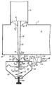
- Figure 1 shows a conceptual diagram of part of a gas meter including a governor.
- the gas meter 2 includes an inlet boss 4 for receiving an unregulated supply of gas.
- the meter contains a chamber 6 in which a regulated volume of gas is contained for subsequent supply to the consumer.
- the flow of gas from the inlet boss 4 to the chamber 6 is controlled by a governor.
- the governor comprises a valve 8 which includes a valve head 10 and a valve stem 12.
- the valve stem extends through the chamber 6 via an opening 14.
- the valve head 10 is suitably shaped so that in operation it can move from the valve seat 16 to provide an opening through which the unregulated gas supply can pass into the chamber 6. It will be appreciated that the amount by which the valve is open determines the regulation of the gas supply.
- the valve stem has a bore 18 throughout its length, and at an end remote from the valve head 10 has an opening 20 through which the unregulated gas supply can vent.
- the valve stem 12 after passing through the opening 14 extends into a system of diaphragms external to the chamber 6.
- a first diaphragm 22 sealably surrounds the opening 14 so that the regulated gas can pass into a chamber 24 created by the diaphragm 22 and the external surface of the chamber 6.
- the valve stem passes through the diaphragm 22 into a chamber 28 and then via a low friction seal and valve guide 30 into a chamber 32.
- the valve stem 12 is sealably attached to the diaphragm 22.
- the valve stem 12 is connected at an end thereof opposite to the valve head 10 to a second larger diaphragm 34.
- the diaphragm 34 is contained within a housing 36 which defines the chamber 32 and a further chamber 38.
- the chamber 38 is vented to the atmosphere via an orifice 40.
- the diaphragm 34 is biased by a spring 42 which is connected to the diaphragm and extends across the chamber 38 to the base of the housing 36.
- the spring 42 is tensioned by a thumb screw 44 which extends through the base of the housing 36 and is connected to the spring 42.
- the orifice 20 located within the valve stem 12 allows the unregulated gas supply to enter the chamber 28.
- a control valve 46 is controlled by a solenoid 48 and in its normal operating state connects the regulated gas in chamber 6 to the chamber 32 via conduits 50, 52. In its alternative operating state, the chamber 32 is connected to the chamber 28 via conduits 50, 54.
- control valve 46 is operated by the solenoid 48 to connect the regulated gas in chamber 6 to the chamber 32 via the conduits 50, 52.
- the governor When the meter is installed the governor is adjusted in the same way as a normal stand alone governor, to provide the correct downstream pressure by altering the pressure applied by the spring 42 and hence to the diaphragms 34, 22, by using the adjusting screw 44.
- the governor causes the valve 8 to be open permitting the required amount of gas to flow from the inlet boss 4 into the chamber 6 thereby regulating the flow of gas.
- the inlet pressure of the gas supply varies, the unregulated gas flowing through the valve stem 12 via the bore 18 passes into the chamber 28 thereby altering the pressure in that chamber and causing the diaphragm 22 to flex accordingly.
- This causes a volume of gas in chamber 22 to pass into the chamber 6, which in turn causes a flow of gas via the conduit 52, 50 into the chamber 32.
- the pressure of the volume of gas in chamber 32 therefore varies accordingly.
- the governor can also be used to cut off the supply of gas to a consumer. This is effected by the valve 46 being operated by the solenoid 48 so that the conduit 50 is connected to the conduit 54. This effectively connects the chamber 32 with the chamber 28. In this mode of operation, the force of equilibrium is upset by increasing the force F d20 by using the inlet pressure instead of the outlet pressure. This results in an overriding force acting to shut the valve 8 thereby preventing the flow of gas into the chamber 6.
Landscapes
- Physics & Mathematics (AREA)
- Fluid Mechanics (AREA)
- General Physics & Mathematics (AREA)
- Engineering & Computer Science (AREA)
- Automation & Control Theory (AREA)
- Measuring Volume Flow (AREA)
- Transition And Organic Metals Composition Catalysts For Addition Polymerization (AREA)
- Glass Compositions (AREA)
- Fluid-Driven Valves (AREA)
- Feeding And Controlling Fuel (AREA)
Applications Claiming Priority (2)
| Application Number | Priority Date | Filing Date | Title |
|---|---|---|---|
| GB9600111A GB2308892B (en) | 1996-01-04 | 1996-01-04 | Improvements in or relating to meters |
| GB9600111 | 1996-01-19 |
Publications (2)
| Publication Number | Publication Date |
|---|---|
| EP0783145A1 true EP0783145A1 (de) | 1997-07-09 |
| EP0783145B1 EP0783145B1 (de) | 2001-10-17 |
Family
ID=10786586
Family Applications (1)
| Application Number | Title | Priority Date | Filing Date |
|---|---|---|---|
| EP96119340A Expired - Lifetime EP0783145B1 (de) | 1996-01-04 | 1996-12-03 | Verbesserungen von oder bei Zählern |
Country Status (4)
| Country | Link |
|---|---|
| US (1) | US5746245A (de) |
| EP (1) | EP0783145B1 (de) |
| AT (1) | ATE207215T1 (de) |
| GB (1) | GB2308892B (de) |
Cited By (2)
| Publication number | Priority date | Publication date | Assignee | Title |
|---|---|---|---|---|
| EP1014244A1 (de) * | 1998-12-25 | 2000-06-28 | Advance Denki Kougyou Kabushiki Kaisha | Durchfluss-Regelventil |
| CN101900213A (zh) * | 2010-07-09 | 2010-12-01 | 杭州浙大精益机电技术工程有限公司 | 带有循环的膜片式流量调节阀 |
Families Citing this family (8)
| Publication number | Priority date | Publication date | Assignee | Title |
|---|---|---|---|---|
| DE10019049C2 (de) * | 2000-04-18 | 2002-04-18 | Mertik Maxitrol Gmbh & Co Kg | Gasdruckregler |
| US6749173B2 (en) * | 2002-09-27 | 2004-06-15 | The Hartfiel Company | Valve arrangement and method of directing fluid flow |
| US6913008B2 (en) * | 2003-01-16 | 2005-07-05 | New Archery Products Corp. | Apparatus for holding arrow |
| US6923197B2 (en) * | 2003-01-30 | 2005-08-02 | Keyspan Energy | Pressure regulator with tamper-proof safety feature |
| US6929026B1 (en) * | 2003-03-28 | 2005-08-16 | Joseph Wilfred Arlinghaus, Jr. | Sanitary liquid pressure regulator |
| JP4330505B2 (ja) * | 2004-08-26 | 2009-09-16 | サーパス工業株式会社 | 液体用レギュレータ |
| JP5968660B2 (ja) * | 2012-03-27 | 2016-08-10 | 株式会社不二工機 | 減圧弁 |
| JP6050039B2 (ja) * | 2012-07-03 | 2016-12-21 | 株式会社不二工機 | 減圧弁 |
Citations (3)
| Publication number | Priority date | Publication date | Assignee | Title |
|---|---|---|---|---|
| FR1047494A (fr) * | 1951-06-22 | 1953-12-15 | Appareil combiné comportant un régulateur de pression et au dispositif de raccordement pour compteur à gaz | |
| FR1264276A (fr) * | 1960-07-28 | 1961-06-19 | Kromschroeder Ag G | Régulateur de pression à commande par membrane |
| EP0076767A1 (de) * | 1981-10-07 | 1983-04-13 | Gaz De France | Vorrichtung zum Regeln und Zählen des Gasdurchflusses |
Family Cites Families (14)
| Publication number | Priority date | Publication date | Assignee | Title |
|---|---|---|---|---|
| US693170A (en) * | 1901-10-31 | 1902-02-11 | Harper F Smith | Fluid-pressure regulator. |
| FR767671A (de) * | 1933-02-08 | 1934-07-20 | ||
| US2162779A (en) * | 1936-04-27 | 1939-06-20 | Illinois Engineering Company | Pressure regulator |
| US3139900A (en) * | 1960-05-30 | 1964-07-07 | Bronzavia Sa | Balanced air loaded air pressure regulator |
| US3207468A (en) * | 1961-08-30 | 1965-09-21 | Orbit Valve Co | Valve or the like having a pressure fluid actuated transducer |
| US3433262A (en) * | 1965-11-18 | 1969-03-18 | Itt | Bilevel pressure regulating valve |
| GB1138996A (en) * | 1966-03-11 | 1969-01-01 | Kromschroeder Ag G | Fluid pressure regulator |
| US3392749A (en) * | 1966-08-18 | 1968-07-16 | American Meter Co | Pressure regulator with balancing piston |
| US3989060A (en) * | 1975-05-29 | 1976-11-02 | Textron, Inc. | Gas pressure regulator |
| US4016905A (en) * | 1976-02-06 | 1977-04-12 | Marlatt Sr John W | Regulator for liquefied petroleum gas systems |
| DE3525331A1 (de) * | 1985-07-16 | 1987-01-29 | Rexroth Mannesmann Gmbh | Hydraulisch betaetigtes selbstschliessendes zwei-wege-sitzventil |
| US5109692A (en) * | 1988-08-25 | 1992-05-05 | Fisher Controls International Inc. | Diagnostic apparatus and method for fluid control valves |
| US4961441A (en) * | 1989-11-13 | 1990-10-09 | Salter Stuart C | Method and system for controlling a pressure regulator |
| GB9321779D0 (en) * | 1993-10-22 | 1993-12-15 | Delta Fluid Products Ltd | Fluid pressure regulator |
-
1996
- 1996-01-04 GB GB9600111A patent/GB2308892B/en not_active Expired - Fee Related
- 1996-12-03 EP EP96119340A patent/EP0783145B1/de not_active Expired - Lifetime
- 1996-12-03 AT AT96119340T patent/ATE207215T1/de not_active IP Right Cessation
-
1997
- 1997-01-02 US US08/778,193 patent/US5746245A/en not_active Expired - Fee Related
Patent Citations (3)
| Publication number | Priority date | Publication date | Assignee | Title |
|---|---|---|---|---|
| FR1047494A (fr) * | 1951-06-22 | 1953-12-15 | Appareil combiné comportant un régulateur de pression et au dispositif de raccordement pour compteur à gaz | |
| FR1264276A (fr) * | 1960-07-28 | 1961-06-19 | Kromschroeder Ag G | Régulateur de pression à commande par membrane |
| EP0076767A1 (de) * | 1981-10-07 | 1983-04-13 | Gaz De France | Vorrichtung zum Regeln und Zählen des Gasdurchflusses |
Cited By (5)
| Publication number | Priority date | Publication date | Assignee | Title |
|---|---|---|---|---|
| EP1014244A1 (de) * | 1998-12-25 | 2000-06-28 | Advance Denki Kougyou Kabushiki Kaisha | Durchfluss-Regelventil |
| US6199582B1 (en) | 1998-12-25 | 2001-03-13 | Advance Denki Kougyou Kabushiki | Flow control valve |
| KR100580809B1 (ko) * | 1998-12-25 | 2006-05-16 | 아드반스 덴키 고교 가부시키가이샤 | 유량제어밸브 |
| CN101900213A (zh) * | 2010-07-09 | 2010-12-01 | 杭州浙大精益机电技术工程有限公司 | 带有循环的膜片式流量调节阀 |
| CN101900213B (zh) * | 2010-07-09 | 2012-01-25 | 杭州浙大精益机电技术工程有限公司 | 带有循环的膜片式流量调节阀 |
Also Published As
| Publication number | Publication date |
|---|---|
| GB2308892A (en) | 1997-07-09 |
| ATE207215T1 (de) | 2001-11-15 |
| GB2308892B (en) | 1999-10-13 |
| EP0783145B1 (de) | 2001-10-17 |
| US5746245A (en) | 1998-05-05 |
| GB9600111D0 (en) | 1996-03-06 |
Similar Documents
| Publication | Publication Date | Title |
|---|---|---|
| EP2288973B1 (de) | Vorrichtung zum regeln eines fluidflusses | |
| EP2281225B1 (de) | Druckbeaufschlagter dienstregler mit druckausgleichstrimmung | |
| US6666015B2 (en) | Simplified fuel control for use with a positive displacement pump | |
| EP1269280B1 (de) | Druck unabhangiger regulierventil | |
| US6418956B1 (en) | Pressure controller | |
| US4664136A (en) | Pressure regulating transducer | |
| EP1151364B1 (de) | Verfahren und vorrichtung zur regelung des druckes eines gasstromes | |
| EP0783145A1 (de) | Verbesserungen von oder bei Zählern | |
| EP0105808A2 (de) | Abgasrückführungssystem | |
| US2891784A (en) | Pressure regulator with associated relief valve | |
| US4640093A (en) | Fuel metering system | |
| EP1621949A3 (de) | Druckregler | |
| JPH05187897A (ja) | 流体計量装置 | |
| WO2000079164A1 (en) | Regulator arrangement | |
| US3971409A (en) | Pressure regulator for pneumatic systems | |
| JPH0719452A (ja) | 調整弁 | |
| US4217928A (en) | Gas regulator valve with step opening characteristic | |
| GB2284687A (en) | Fluid pressure regulator | |
| SU840832A1 (ru) | Регул тор пр мого действи | |
| US3683949A (en) | Pneumatic control system and method of operating the same or the like | |
| SU1383313A1 (ru) | Регул тор давлени | |
| US361796A (en) | Pressure-regulator | |
| SU767718A1 (ru) | Регул тор давлени газа | |
| SU1758636A1 (ru) | Регул тор давлени газа | |
| RU1807468C (ru) | Регул тор давлени газа |
Legal Events
| Date | Code | Title | Description |
|---|---|---|---|
| PUAI | Public reference made under article 153(3) epc to a published international application that has entered the european phase |
Free format text: ORIGINAL CODE: 0009012 |
|
| AK | Designated contracting states |
Kind code of ref document: A1 Designated state(s): AT BE GB LU NL |
|
| 17P | Request for examination filed |
Effective date: 19971208 |
|
| 17Q | First examination report despatched |
Effective date: 19990825 |
|
| RAP1 | Party data changed (applicant data changed or rights of an application transferred) |
Owner name: SIEMENS METERING LIMITED |
|
| GRAG | Despatch of communication of intention to grant |
Free format text: ORIGINAL CODE: EPIDOS AGRA |
|
| GRAG | Despatch of communication of intention to grant |
Free format text: ORIGINAL CODE: EPIDOS AGRA |
|
| GRAH | Despatch of communication of intention to grant a patent |
Free format text: ORIGINAL CODE: EPIDOS IGRA |
|
| GRAH | Despatch of communication of intention to grant a patent |
Free format text: ORIGINAL CODE: EPIDOS IGRA |
|
| GRAA | (expected) grant |
Free format text: ORIGINAL CODE: 0009210 |
|
| AK | Designated contracting states |
Kind code of ref document: B1 Designated state(s): AT BE GB LU NL |
|
| PG25 | Lapsed in a contracting state [announced via postgrant information from national office to epo] |
Ref country code: NL Free format text: LAPSE BECAUSE OF FAILURE TO SUBMIT A TRANSLATION OF THE DESCRIPTION OR TO PAY THE FEE WITHIN THE PRESCRIBED TIME-LIMIT Effective date: 20011017 Ref country code: BE Free format text: LAPSE BECAUSE OF FAILURE TO SUBMIT A TRANSLATION OF THE DESCRIPTION OR TO PAY THE FEE WITHIN THE PRESCRIBED TIME-LIMIT Effective date: 20011017 Ref country code: AT Free format text: LAPSE BECAUSE OF FAILURE TO SUBMIT A TRANSLATION OF THE DESCRIPTION OR TO PAY THE FEE WITHIN THE PRESCRIBED TIME-LIMIT Effective date: 20011017 |
|
| REF | Corresponds to: |
Ref document number: 207215 Country of ref document: AT Date of ref document: 20011115 Kind code of ref document: T |
|
| PGFP | Annual fee paid to national office [announced via postgrant information from national office to epo] |
Ref country code: GB Payment date: 20011205 Year of fee payment: 6 |
|
| PGFP | Annual fee paid to national office [announced via postgrant information from national office to epo] |
Ref country code: LU Payment date: 20011207 Year of fee payment: 6 |
|
| PGFP | Annual fee paid to national office [announced via postgrant information from national office to epo] |
Ref country code: AT Payment date: 20011212 Year of fee payment: 6 |
|
| PGFP | Annual fee paid to national office [announced via postgrant information from national office to epo] |
Ref country code: NL Payment date: 20011228 Year of fee payment: 6 |
|
| REG | Reference to a national code |
Ref country code: GB Ref legal event code: IF02 |
|
| PGFP | Annual fee paid to national office [announced via postgrant information from national office to epo] |
Ref country code: BE Payment date: 20020218 Year of fee payment: 6 |
|
| NLV1 | Nl: lapsed or annulled due to failure to fulfill the requirements of art. 29p and 29m of the patents act | ||
| PLBE | No opposition filed within time limit |
Free format text: ORIGINAL CODE: 0009261 |
|
| STAA | Information on the status of an ep patent application or granted ep patent |
Free format text: STATUS: NO OPPOSITION FILED WITHIN TIME LIMIT |
|
| 26N | No opposition filed | ||
| PG25 | Lapsed in a contracting state [announced via postgrant information from national office to epo] |
Ref country code: LU Free format text: LAPSE BECAUSE OF NON-PAYMENT OF DUE FEES Effective date: 20021203 Ref country code: GB Free format text: LAPSE BECAUSE OF NON-PAYMENT OF DUE FEES Effective date: 20021203 |
|
| GBPC | Gb: european patent ceased through non-payment of renewal fee |