EP0782069A1 - Pseudozufallszahlengenerator - Google Patents
Pseudozufallszahlengenerator Download PDFInfo
- Publication number
- EP0782069A1 EP0782069A1 EP96120661A EP96120661A EP0782069A1 EP 0782069 A1 EP0782069 A1 EP 0782069A1 EP 96120661 A EP96120661 A EP 96120661A EP 96120661 A EP96120661 A EP 96120661A EP 0782069 A1 EP0782069 A1 EP 0782069A1
- Authority
- EP
- European Patent Office
- Prior art keywords
- pseudorandom number
- shift register
- function circuit
- nonlinear function
- number generator
- Prior art date
- Legal status (The legal status is an assumption and is not a legal conclusion. Google has not performed a legal analysis and makes no representation as to the accuracy of the status listed.)
- Withdrawn
Links
Images


Classifications
-
- G—PHYSICS
- G06—COMPUTING; CALCULATING OR COUNTING
- G06F—ELECTRIC DIGITAL DATA PROCESSING
- G06F7/00—Methods or arrangements for processing data by operating upon the order or content of the data handled
- G06F7/58—Random or pseudo-random number generators
- G06F7/582—Pseudo-random number generators
-
- H—ELECTRICITY
- H04—ELECTRIC COMMUNICATION TECHNIQUE
- H04L—TRANSMISSION OF DIGITAL INFORMATION, e.g. TELEGRAPHIC COMMUNICATION
- H04L9/00—Cryptographic mechanisms or cryptographic arrangements for secret or secure communications; Network security protocols
- H04L9/06—Cryptographic mechanisms or cryptographic arrangements for secret or secure communications; Network security protocols the encryption apparatus using shift registers or memories for block-wise or stream coding, e.g. DES systems or RC4; Hash functions; Pseudorandom sequence generators
- H04L9/065—Encryption by serially and continuously modifying data stream elements, e.g. stream cipher systems, RC4, SEAL or A5/3
- H04L9/0656—Pseudorandom key sequence combined element-for-element with data sequence, e.g. one-time-pad [OTP] or Vernam's cipher
- H04L9/0662—Pseudorandom key sequence combined element-for-element with data sequence, e.g. one-time-pad [OTP] or Vernam's cipher with particular pseudorandom sequence generator
- H04L9/0668—Pseudorandom key sequence combined element-for-element with data sequence, e.g. one-time-pad [OTP] or Vernam's cipher with particular pseudorandom sequence generator producing a non-linear pseudorandom sequence
-
- H—ELECTRICITY
- H04—ELECTRIC COMMUNICATION TECHNIQUE
- H04L—TRANSMISSION OF DIGITAL INFORMATION, e.g. TELEGRAPHIC COMMUNICATION
- H04L9/00—Cryptographic mechanisms or cryptographic arrangements for secret or secure communications; Network security protocols
- H04L9/12—Transmitting and receiving encryption devices synchronised or initially set up in a particular manner
-
- H—ELECTRICITY
- H04—ELECTRIC COMMUNICATION TECHNIQUE
- H04L—TRANSMISSION OF DIGITAL INFORMATION, e.g. TELEGRAPHIC COMMUNICATION
- H04L2209/00—Additional information or applications relating to cryptographic mechanisms or cryptographic arrangements for secret or secure communication H04L9/00
- H04L2209/12—Details relating to cryptographic hardware or logic circuitry
- H04L2209/122—Hardware reduction or efficient architectures
Definitions
- the present invention relates to a pseudorandom number generator for generating pseudorandom numbers.
- Communication systems and computer systems employ stream cipher apparatus or the like for converting information into enciphered information by adding pseudorandom numbers to the information through an exclusive-OR operation and recovering original information by adding pseudorandom numbers to enciphered information through an exclusive-OR operation in order to prevent an unauthorized person from gaining an unlawful access to the information.
- Pseudorandom numbers used to encrypt information to prevent an unauthorized access to the information are required to be highly nonlinear.
- output signals from a plurality of pseudorandom number generating circuits are nonlinearly combined by a nonlinear function called a combining function to generate pseudorandom numbers that are more highly nonlinear.
- the pseudorandom number generating circuit is a basic circuit, such as a linear feedback shift register or the like, for producing pseudorandom numbers.
- a pseudorandom number generator includes one or more such pseudorandom number generating circuits and generates pseudorandom numbers of higher nonlinearity.
- a nonlinear combination is a combination which is not a linear combination.
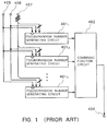
- FIG. 1 is a functional block diagram of an example of a conventional pseudorandom number generator.
- the conventional pseudorandom number generator comprises n pseudorandom number generating circuits 401 1 to 401 n where n is an integer of 2 or higher, a combining function circuit 402 for nonlinearly combining outputs from the n pseudorandom number generating circuits 401 1 to 401 n to produce a pseudorandom number from an output terminal 408, an input terminal 405 for being supplied with a control pulse (a clock pulse), an input terminal 406 for mode control, and an input terminal 407 for parallelly inputting a bit sequence called an initial state.
- a control pulse a clock pulse
- an input terminal 406 for mode control
- an input terminal 407 for parallelly inputting a bit sequence called an initial state.
- Each of the pseudorandom number generating circuits 401 1 to 401 n is connected to the input terminals 405, 406 and 407. If a control pulse is inputted to the input terminal 405 while a signal "0" is being supplied to the input terminal 406, then each of the pseudorandom number generating circuits 401 1 to 401 n reads the initial state supplied from the input terminal 407 and holds it as an internal state. Each time a control pulse is inputted to the input terminal 405 while a signal "1" is being supplied to the input terminal 406, then each of the pseudorandom number generating circuits 401 1 to 401 n outputs a pseudorandom number. Generally, the pseudorandom number generating circuits 401 1 to 401 n are supplied with respective different initial states.
- a pseudorandom number is generated by the pseudorandom number generator shown in FIG. 1 as follows: First, an initial state is supplied to the input terminal 407, then a signal "0" is supplied to the input terminal 406, and a control pulse is inputted to the input terminal 405. Then, a signal "1" is supplied to the input terminal 406. Subsequently, each time a control pulse is inputted to the input terminal 405, the combining function circuit 402 nonlinearly combines the outputs from the pseudorandom number generating circuits 401 1 to 401 n to generate a pseudorandom number, which is outputted from the output terminal 408.
- the conventional pseudorandom number generator is problematic in that the initial states set in the respective pseudorandom number generating circuits 401 1 to 401 n may be estimated by a deciphering process known as a correlation attack, allowing encrypted information to be unlawfully deciphered.
- a conditional probability distribution of an output from the combining function circuit 402 which is conditioned by an output from a certain pseudorandom number generating circuit 401 j (1 ⁇ j ⁇ n) is not uniform, then a pseudorandom number sequence generating circuit equivalent to the pseudorandom number generating circuit 401 j may be presumed, and an initial state of the pseudorandom number sequence generating circuit may be determined in order to maximize the correlation between an output sequence of the pseudorandom number sequence generating circuit and an output sequence of the combining function circuit 402, for thereby recognizing an initial state given to the pseudorandom number generating circuit 401 j .
- the present inventor has proposed a pseudorandom number generator which does not use a bit stream outputted by a combining function circuit, but a bit stream produced when an output from the combining function circuit is convoluted, as a pseudorandom number, as disclosed in Japanese unexamined patent publication (Kokai) No. Hei 7-104976 (JP, A, 7-104976).
- Using a bit stream produced when an output from the combining function circuit is convoluted as a pseudorandom number substantially uniformizes a conditional probability distribution of pseudorandom numbers which is conditioned by an output from a certain pseudorandom number generating circuit, making it difficult to decipher encrypted information with a correlation attack.
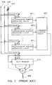
- FIG. 2 shows in functional block form a conventional pseudorandom number generator which is designed to protect itself from a correlation attack.
- the pseudorandom number generator shown in FIG. 2 differs from the pseudorandom number generator shown in FIG. 1 in that a shift register 410 and an exclusive-OR gate 411 are inserted between the combining function circuit 402 and the output terminal 408.
- the shift register 410 is also connected to the input terminals 405, 406 and 407. If a control pulse is inputted to the input terminal 405 while a signal "0" is being supplied to the input terminal 406, then the shift register 410 reads a bit sequence, called an initial state, supplied from the input terminal 407 and holds it as an internal state.
- the shift register 410 shifts the internal state one bit to the right and holds an output from the combining function circuit 402 at an left end bit therein.
- the exclusive-OR gate 411 calculates a linear combination of predetermined bits in the internal state of the shift register 410, and the calculated linear combination is outputted as a pseudorandom number from the output terminal 408. As indicated by the dotted line in FIG. 2, the output from the combining function circuit 402 may also be applied to the exclusive-OR gate 411.
- an initial state is supplied to the input terminal 407, then a signal "0" is supplied to the input terminal 406, and a control pulse is inputted to the input terminal 405. Then, a signal "1" is supplied to the input terminal 406. Subsequently, each time a control pulse is inputted to the input terminal 405, a pseudorandom number is outputted from the output terminal 408.
- FIG. 3 shows an internal structure of the shift register 410.
- the shift register 410 has m stages, and includes a clock input terminal 415, a mode switching signal input terminal 416, an internal state input terminal 417 for establishing an internal state in the shift register 410, an internal state output terminal 418 for outputting the internal state of the shift register 410, a shift input terminal 419, m selectors 421 1 to 421 m of 2-input for making selections in response to a signal inputted to the mode switching signal input terminal 416, and m D-type flip-flops 422 1 to 422 m .
- the D-type flip-flops 422 1 to 422 m are clocked by a clock signal inputted to the clock input terminal 415, for receiving respective outputs from the selectors 421 1 to 421 m .
- An output sequence from the D-type flip-flops 422 1 to 422 m is referred to as an internal state of the shift register 410.
- the clock input terminal 415 is connected to the input terminal 405, the mode switching signal input terminal 416 to the input terminal 406, the internal state input terminal 417 to the input terminal 407, and the shift input terminal 419 to the output terminal of the combining function circuit 402.
- the selector 421 1 on the left end in the shift register 410 is supplied with an output from the combining function circuit 402 (see FIG. 2) through the shift input terminal 419 and one bit of the internal state inputted from the internal state input terminal 417.
- the selectors 421 1 to 421 m select and output respective bits supplied from the internal state input terminal 417.
- the selectors 421 1 to 421 m select and output a signal from the shift input terminal 419 and signals from the preceding D-type flip-flops 422 1 to 422 m-1 .
- the D-type flip-flops 422 1 to 422 m hold respective outputs from the selectors 421 1 to 421 m , and output the held values.
- the outputs from the respective D-type flip-flops 422 1 to 422 m are outputted as parallel m bits from the internal state output terminal 418, and some of the outputted bits are inputted to the exclusive-OR gate 411 (see FIG. 2).
- each of the pseudorandom number generating circuits 401 1 to 401 n may be a pseudorandom number generating circuit 501 which comprises only a linear feedback shift register as shown in FIG. 4 or a pseudorandom number generating circuit 511 which comprises a combination of a nonlinear function circuit and a linear feedback shift register as shown in FIG. 5.
- each of the pseudorandom number generating circuits 401 1 to 401 n may be of another different circuit arrangement.
- the pseudorandom number generating circuit 501 which comprises only a linear feedback shift register as shown in FIG. 4 will be described below.
- the pseudorandom number generating circuit 501 comprises a shift register 502 and an exclusive-OR gate 503.
- the shift register 502 is of a structure which is the same as the shift register 410 shown in FIG. 3 though it may have a different number of stages.
- the shift register 502 has a clock input terminal, a mode switching signal input terminal, and an internal state input terminal connected respectively to the input terminals 405, 406 and 407.
- the exclusive-OR gate 503 serves to perform an exclusive-OR operation to the inputted bits and output the result of the exclusive-OR operation.
- the pseudorandom number generating circuit 501 shown in FIG. 4 is a so-called M-sequence (maximum-length linearly recurring sequence) generating circuit.
- the pseudorandom number generating circuit 501 Since the randomness of pseudorandom numbers generated only by the pseudorandom number generating circuit 501 is not so high and its initial state can easily be estimated, the pseudorandom number generating circuit 501 alone is not suitable for generating pseudorandom numbers for the purpose of encrypting information.
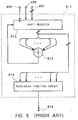
- the pseudorandom number generating circuit 511 shown in FIG. 5 comprises a shift register 512, an exclusive-OR gate 513, and a nonlinear function circuit 514.
- the shift register 512 is of a structure which is the same as the shift register 410 shown in FIG. 3 though it may have a different number of stages.
- the shift register 512 has a clock input terminal, a mode switching signal input terminal, and an internal state input terminal connected respectively to the input terminals 405, 406 and 407. Only predetermined bits of an output from the internal state output terminal of the shift register 512 are supplied to the exclusive-OR gate 513, which supplies its output signal to a shift input terminal to the shift register 512.
- the exclusive-OR gate 513 serves to perform an exclusive-OR operation to the inputted bits and output the result of the exclusive-OR operation. All or predetermined bits of an output from the internal state output terminal of the shift register 512 are supplied to the nonlinear function circuit 514, and nonlinearly combined thereby.
- the nonlinear function circuit 514 outputs a nonlinearly combined signal as a pseudorandom number through an output terminal 515.
- the combining function serves to nonlinearly combine inputted bits and output a nonlinearly combined signal.
- a combining function circuit which outputs a combining function may be implemented by a logic function circuit, a read-only memory (ROM), or a combination thereof.
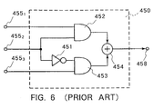
- FIG. 6 is a functional block diagram of a 3-input combining function circuit 450.
- the combining function circuit 450 comprises an inverter 451, a first and second 2-input AND gates 452 and 453, a 2-input exclusive-OR gate 454, first, second, and third input terminals 455 1 to 455 3 for being supplied with pseudorandom numbers generated by respective different pseudorandom number generating circuits, and an output terminal 458 connected to the output terminal of the exclusive-OR gate 454.
- the pseudorandom number inputted to the first input terminal 455 1 is supplied to an input terminal of the first AND gate 452, and the pseudorandom number inputted to the second input terminal 455 2 is supplied to the other input terminal of the first AND gate 452 and the inverter 451.
- the second AND gate 453 is supplied with the pseudorandom number inputted to the third input terminal 455 3 and the pseudorandom number inputted to the second input terminal 455 2 , which has been inverted by the inverter 451.
- the first and second AND gates 452 and 453 perform AND operations to the inputs thereto and output the result signals of the AND operations to the exclusive-OR gate 454.
- the exclusive-OR gate 454 performs an exclusive-OR operation to the outputs of the first and second AND gates 452 and 453 and outputs the result signal of the exclusive-OR operation signal through the output terminal 458.
- the conventional pseudorandom number generators which have been described above in detail suffer drawbacks in that if they have a reduced circuit scale, then they can generate only pseudorandom numbers which have low nonlinearity, and if they are to generate pseudorandom numbers that are highly nonlinear, they are required to be of an increased circuit scale. Specifically, if the circuit scale of a pseudorandom number generator is to be reduced, then it is effective to use pseudorandom number generating circuits comprising only a linear feedback shift register. In such a circuit arrangement, however, only the combining function circuit carries out a nonlinear conversion, and hence fails to produce pseudorandom numbers which are highly nonlinear.
- the above object can be achieved by a pseudorandom number generator having a pseudorandom number generating circuit operable in synchronism with a clock signal and a shift register for shifting stored bits one bit at a time in a direction from one end to the other end thereof in synchronism with the clock signal and storing a signal based on at least an output from the pseudorandom number generating circuit at the one end, wherein the pseudorandom number generator includes a nonlinear function circuit for nonlinearly combining predetermined bits of the stored bits of the shift register and outputting a nonlinearly combined signal, and the nonlinear function circuit outputs a pseudorandom number in synchronism with the clock signal.
- an output sequence from the combining function circuit 402 is held by the shift register 410, and all or predetermined bits of the internal state of the shift register 410 are linearly combined by the exclusive-OR gate 411 thereby generating a pseudorandom number.
- a conditional probability distribution of pseudorandom numbers which is conditioned by an output from a certain pseudorandom number generating circuit 401 j (1 ⁇ j ⁇ n) is made substantially uniform, a correlation attack is difficult to carry out.
- Such a scheme has been used over a long period of time also for the purpose of uniformizing a distribution of random numbers, e.g., random numbers determined by casting dice, which are generated by a physical method. Consequently, a linear combination has been considered to be effective to prevent a correlation attack.
- conditional probability is uniformized by a linear combination not based on the linearity of the linear combination, but based on the uniformity of the linear combination.
- uniformity means that "0"s and "1"s are produced with substantially the same probability by combining randomly given bits. Therefore, it should be able to prevent a correlation attack with a nonlinear combination, rather than a linear combination, insofar as the nonlinear combination is uniform.
- a nonlinear function circuit for nonlinearly combining predetermined bits of the stored bits of a shift register is used in place of the exclusive-OR gate in the conventional pseudorandom number generator shown in FIG. 2, and the predetermined bits of an internal stage of the shift register, which is supplied with an output from a combining function circuit, are nonlinearly combined by the nonlinear function circuit. Then, a nonlinearly combined signal from the nonlinear function circuit is outputted as a pseudorandom number.
- This arrangement allows the pseudorandom number generator to generate highly nonlinear pseudorandom numbers while maintaining its ability to prevent a correlation attack.
- an exclusive-OR gate may be inserted between the combining function circuit and the shift register for supplying the shift register with a signal that is produced by exclusive-OR operation between outputs from the nonlinear function circuit and the combining function circuit. In this manner, the output from the nonlinear function circuit is fed back to the shift register. Even if the nonlinearity of a nonlinear combination performed by the nonlinear function circuit is low, a repetition of conversions with a low nonlinearity is reduced to a conversion with a high nonlinearity as indicated by an example of the square of x becoming x 2 , the square of x 2 becoming x 4 , and the square of x 4 becoming x 8 . It is thus possible for the pseudorandom number generator to generate pseudorandom numbers of higher nonlinearity.
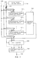
- a pseudorandom number generator according to a first embodiment of the present invention comprises n pseudorandom number generating circuits 101 1 to 101 n where n is an integer of 2 or higher, a combining function circuit 102 for nonlinearly combining outputs from the n pseudorandom number generating circuits 101 1 to 101 n and outputting a nonlinearly combined signal, a shift register 103 which receives the output from the combining function circuit 102 as a shift input thereto, a nonlinear function circuit 104 for calculating a nonlinear combination of predetermined bits of an internal state of the shift register 103 or all stored bits of the shift register 103, an input terminal 105 for being supplied with a control pulse (a clock pulse), an input terminal 106 for mode control, and an input terminal 107 for inputting a bit sequence called an initial state.
- a control pulse a clock pulse
- the result calculated by the nonlinear function circuit 104 is outputted as a bit stream representing a pseudorandom number from an output terminal 108 in synchronism with a clock signal supplied to the input terminal 105.
- the output from the combining function circuit 102 may also be applied to nonlinear function circuit 104.
- Each of the pseudorandom number generating circuits 101 1 to 101 n is connected to the input terminals 105, 106 and 107. If a control pulse is inputted to the input terminal 105 while a signal "0" is being supplied to the input terminal 106, then each of the pseudorandom number generating circuits 101 1 to 101 n reads an initial state supplied from the input terminal 107 and holds it as an internal state. Each time a control pulse is inputted to the input terminal 105 while a signal "1" is being supplied to the input terminal 106, then each of the pseudorandom number generating circuits 101 1 to 101 n outputs a pseudorandom number.
- Each of the pseudorandom number generating circuits 101 1 to 101 n may preferably be a pseudorandom number generating circuit comprising only a linear feedback shift register as shown in FIG. 4.
- the shift register 103 is also connected to the input terminals 105, 106 and 107. If a control pulse is inputted to the input terminal 105 while a signal "0" is being supplied to the input terminal 106, then the shift register 103 holds a bit sequence called an initial state supplied from the input terminal 107 as an internal state.
- the shift register 103 shifts the internal state one bit to the right and holds an output from the combining function circuit 102 at an left end bit therein.
- the shift register 103 may be of the structure shown in FIG. 3.
- the pseudorandom number generating circuits 101 1 to 101 n , the combining function circuit 102, and the input terminals 105, 106 and 107 of the present embodiment correspond respectively to the pseudorandom number generating circuits 401 1 to 401 n , the combining function circuit 402, and the input terminals 405, 406 and 407 provided in the conventional pseudorandom number generator shown in FIGS. 1 and 2.
- the shift register 103 corresponds to the shift register 410 shown in FIG. 2.
- the combining function circuit 102 and the nonlinear function circuit 104 are called differently according to the terminology in the art. However, they are similar to each other in that they perform a nonlinear combining of inputs applied thereto, though they sometimes differ from each other with respect to the number of inputs applied thereto and the internal structure.
- the nonlinear function circuit 104 may comprise any of various optional circuits insofar as they perform a uniform nonlinear combining of inputs applied thereto.
- the nonlinear function circuit 104 may comprise a look-up table stored in a read-only memory (ROM). Specifically, as shown in FIG. 8, equal numbers of "0"s and "1"s are written in a ROM 151, and a plurality of inputs to the nonlinear function circuit 104 are regarded as inputs to a plurality of address input terminals of the ROM 151 for outputting 1-bit data from the ROM 151 as an output from the nonlinear function circuit 104.
- ROM read-only memory
- the nonlinear function circuit 104 may comprise a plurality of ROMs 151 described above and an exclusive-OR gate 152. Outputs from the ROMs 151 may be inputted to the exclusive-OR gate 152, and an output from the exclusive-OR gate 152 may be regarded as an output from the nonlinear function circuit 104.
- the pseudorandom number generating circuits 101 1 to 101 n and the shift register 103 are supplied with different initial states through the input terminal 107. Since each of the initial states supplied to the pseudorandom number generating circuits 101 1 to 101 n and the shift register 103 is represented by a plurality of bits depending on its internal bit width, the bit width of the input terminal 107 may be made equal to a total of the internal bit widths of the pseudorandom number generating circuits 101 1 to 101 n and the shift register 103. Alternatively, the pseudorandom number generating circuits 101 1 to 101 n and the shift register 103 may be controlled independently to set them to respective internal states.
- an initial state setting circuit 110 is connected to the input terminal 107 to generate initial states for the pseudorandom number generating circuits 101 1 to 101 n and the shift register 103 for thereby establishing bit sequences of initial states in the pseudorandom number generating circuits 101 1 to 101 n and the shift register 103.
- initial states for the pseudorandom number generating circuits 101 1 to 101 n and the shift register 103 are supplied from the initial state setting circuit 110 to the input terminal 107. Then, a signal "0" is supplied to the input terminal 106, and a control pulse is inputted to the input terminal 105. As a result, the initial states are established respectively in the pseudorandom number generating circuits 101 1 to 101 n and the shift register 103. Thereafter, a signal "1" is supplied to the input terminal 106. Subsequently, each time a control pulse is inputted to the input terminal 105, one bit of a pseudorandom number is produced from the output terminal 108.
- the pseudorandom number generator according to the present invention employs a nonlinear function circuit for performing a uniform nonlinear combination, rather than a linear combining circuit, in order to uniformize a conditional probability distribution of pseudorandom numbers which is conditioned by an output from a certain pseudorandom number generating circuit. Therefore, pseudorandom numbers generated by the pseudorandom number generator are highly nonlinear, and hence are highly resistant to a correlation attack and suitable for use in producing stream ciphers. Even if each of the pseudorandom number generating circuits comprises a simple linear feedback shift register, the pseudorandom number generator can generate highly nonlinear pseudorandom numbers. Consequently, the pseudorandom number generator according to the present embodiment can generate highly nonlinear pseudorandom numbers with a circuit arrangement of a relatively small scale at a low cost.
- FIG. 10 shows a pseudorandom number generator according to a second embodiment of the present invention.
- the pseudorandom number generator according to the second embodiment differs from the pseudorandom number generator according to the first embodiment in that an exclusive-OR gate 111 is inserted between the combining function circuit 102 and the shift register 103 to supply an output from the exclusive-OR gate 111, rather than an output from the combining function circuit 102, to the shift input terminal of the shift register 103.
- the exclusive-OR gate 111 performs an exclusive-OR operation between outputs from the combining function circuit 102 and the nonlinear function circuit 104, and outputs the result of the exclusive-OR operation.
- the pseudorandom number generator according to the second embodiment because the output from the nonlinear function circuit 104 is fed back to the shift register 103 through the exclusive-OR gate 111, a highly nonlinear pseudorandom number can be produced from the output terminal 108 even if the nonlinearity of the nonlinear function circuit 104 is low. Therefore, the nonlinear function circuit 104 may be of a reduced circuit scale.
- the pseudorandom number generator according to the second embodiment produces a pseudorandom number in the same manner as the pseudorandom number generator according to the first embodiment.
- the nonlinearity of the pseudorandom number generator is increased by the nonlinear function circuit 104 connected to the output terminal 108.
- the pseudorandom number generator may be able to generate pseudorandom numbers which are sufficiently highly nonlinear even if it has one pseudorandom number generating circuit.
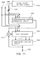
- a pseudorandom number generator has a single pseudorandom number generating circuit 101. Since only one pseudorandom number generating circuit 101 is used, no combining function circuit is required, and an output from the pseudorandom number generating circuit 101 is inputted directly to the exclusive-OR gate 111.
- Other structural details and operation of the pseudorandom number generator according to the third embodiment are identical to those of the pseudorandom number generator according to the second embodiment.
Landscapes
- Engineering & Computer Science (AREA)
- Physics & Mathematics (AREA)
- Theoretical Computer Science (AREA)
- General Physics & Mathematics (AREA)
- Computer Networks & Wireless Communication (AREA)
- Signal Processing (AREA)
- Computer Security & Cryptography (AREA)
- Mathematical Optimization (AREA)
- Mathematical Analysis (AREA)
- Computational Mathematics (AREA)
- Pure & Applied Mathematics (AREA)
- General Engineering & Computer Science (AREA)
- Nonlinear Science (AREA)
- Tests Of Electronic Circuits (AREA)
- Mobile Radio Communication Systems (AREA)
- Test And Diagnosis Of Digital Computers (AREA)
Applications Claiming Priority (2)
| Application Number | Priority Date | Filing Date | Title |
|---|---|---|---|
| JP7336920A JPH09179726A (ja) | 1995-12-25 | 1995-12-25 | 擬似乱数発生装置 |
| JP336920/95 | 1995-12-25 |
Publications (1)
| Publication Number | Publication Date |
|---|---|
| EP0782069A1 true EP0782069A1 (de) | 1997-07-02 |
Family
ID=18303859
Family Applications (1)
| Application Number | Title | Priority Date | Filing Date |
|---|---|---|---|
| EP96120661A Withdrawn EP0782069A1 (de) | 1995-12-25 | 1996-12-20 | Pseudozufallszahlengenerator |
Country Status (4)
| Country | Link |
|---|---|
| EP (1) | EP0782069A1 (de) |
| JP (1) | JPH09179726A (de) |
| AU (1) | AU7539696A (de) |
| CA (1) | CA2193196A1 (de) |
Cited By (14)
| Publication number | Priority date | Publication date | Assignee | Title |
|---|---|---|---|---|
| EP0905611A2 (de) * | 1997-09-24 | 1999-03-31 | Nec Corporation | Verfahren zur Erzeugung von Pseudozufallszahlen und Pseudozufallszahlengenerator |
| EP1049288A2 (de) * | 1999-04-30 | 2000-11-02 | Texas Instruments Incorporated | Pseudozufallsfolge |
| WO2002071204A1 (en) * | 2001-03-01 | 2002-09-12 | Corrent Corporation | Random number generator based on permutation, substitution, compression and a plurality of variable frequency clocks |
| WO2003042813A2 (fr) * | 2001-11-15 | 2003-05-22 | Everbee Networks | Procede pour generer des nombres aleatoires |
| US6593788B1 (en) | 1999-03-11 | 2003-07-15 | Richard Vogts | Random signal generator and method for generating a random signal |
| FR2859290A1 (fr) * | 2003-08-29 | 2005-03-04 | Infineon Technologies Ag | Generateur de nombres pseudoaleatoires |
| WO2006015625A1 (en) * | 2004-08-09 | 2006-02-16 | Telecom Italia S.P.A. | Method and apparatus for generating random data |
| WO2007052045A3 (en) * | 2005-11-04 | 2007-10-18 | Isis Innovation | Security in computing networks |
| CN100459493C (zh) * | 2005-12-29 | 2009-02-04 | 北京浦奥得数码技术有限公司 | 流密码生成器、随机数生成方法、加密系统及加密方法 |
| US7526088B2 (en) | 2002-03-05 | 2009-04-28 | Cordes Rene-Michael | Code generator and device for the synchronous or asynchronous and permanent identification or encoding and decoding of data of any particular length |
| US8150900B2 (en) | 2004-08-09 | 2012-04-03 | Telecom Italia S.P.A. | Random number generation based on logic circuits with feedback |
| US8230229B2 (en) | 2005-11-04 | 2012-07-24 | Isis Innovation Limited | Security in computing networks |
| CN108139889A (zh) * | 2015-10-12 | 2018-06-08 | 甲骨文国际公司 | 通过多个辅助伪随机数生成器的非线性混合生成伪随机数序列 |
| CN112379858A (zh) * | 2020-11-13 | 2021-02-19 | 北京灵汐科技有限公司 | 随机数的产生方法及装置、电子设备和可读存储介质 |
Families Citing this family (4)
| Publication number | Priority date | Publication date | Assignee | Title |
|---|---|---|---|---|
| WO2004032098A1 (ja) * | 2002-10-07 | 2004-04-15 | Kobayashi, Akira | 疑似乱数発生方法及び疑似乱数発生器 |
| WO2005073842A1 (ja) * | 2004-01-30 | 2005-08-11 | Victor Company Of Japan, Limited | 擬似乱数生成装置および擬似乱数生成プログラム |
| US20090327382A1 (en) * | 2006-07-25 | 2009-12-31 | Nec Corporation | Pseudo-random number generation device, stream encryption device and program |
| JP5191727B2 (ja) * | 2007-12-21 | 2013-05-08 | 株式会社ジャパンディスプレイイースト | 表示装置 |
Citations (3)
| Publication number | Priority date | Publication date | Assignee | Title |
|---|---|---|---|---|
| US4161041A (en) * | 1978-10-06 | 1979-07-10 | The United States Of America As Represented By The Secretary Of The Air Force | Pseudo random number generator apparatus |
| US4202051A (en) * | 1977-10-03 | 1980-05-06 | Wisconsin Alumni Research Foundation | Digital data enciphering and deciphering circuit and method |
| JPH07104976A (ja) * | 1993-10-06 | 1995-04-21 | Nec Corp | 擬似乱数発生装置 |
-
1995
- 1995-12-25 JP JP7336920A patent/JPH09179726A/ja active Pending
-
1996
- 1996-12-16 AU AU75396/96A patent/AU7539696A/en not_active Abandoned
- 1996-12-17 CA CA 2193196 patent/CA2193196A1/en not_active Abandoned
- 1996-12-20 EP EP96120661A patent/EP0782069A1/de not_active Withdrawn
Patent Citations (4)
| Publication number | Priority date | Publication date | Assignee | Title |
|---|---|---|---|---|
| US4202051A (en) * | 1977-10-03 | 1980-05-06 | Wisconsin Alumni Research Foundation | Digital data enciphering and deciphering circuit and method |
| US4161041A (en) * | 1978-10-06 | 1979-07-10 | The United States Of America As Represented By The Secretary Of The Air Force | Pseudo random number generator apparatus |
| JPH07104976A (ja) * | 1993-10-06 | 1995-04-21 | Nec Corp | 擬似乱数発生装置 |
| US5566099A (en) * | 1993-10-06 | 1996-10-15 | Nec Corporation | Pseudorandom number generator |
Non-Patent Citations (1)
| Title |
|---|
| HOLLMANN H: "DESIGN OF TEST SEQUENCES FOR VLSI SELF-TESTING USING LFSR", IEEE TRANSACTIONS ON INFORMATION THEORY, vol. 36, no. 2, 1 March 1990 (1990-03-01), pages 386 - 392, XP000132571 * |
Cited By (26)
| Publication number | Priority date | Publication date | Assignee | Title |
|---|---|---|---|---|
| EP0905611A3 (de) * | 1997-09-24 | 2001-07-04 | Nec Corporation | Verfahren zur Erzeugung von Pseudozufallszahlen und Pseudozufallszahlengenerator |
| EP0905611A2 (de) * | 1997-09-24 | 1999-03-31 | Nec Corporation | Verfahren zur Erzeugung von Pseudozufallszahlen und Pseudozufallszahlengenerator |
| US6593788B1 (en) | 1999-03-11 | 2003-07-15 | Richard Vogts | Random signal generator and method for generating a random signal |
| EP1049288A2 (de) * | 1999-04-30 | 2000-11-02 | Texas Instruments Incorporated | Pseudozufallsfolge |
| EP1049288A3 (de) * | 1999-04-30 | 2002-06-12 | Texas Instruments Incorporated | Pseudozufallsfolge |
| US6895090B1 (en) | 1999-04-30 | 2005-05-17 | Texas Instruments Incorporated | Pseudo-noise sequence with insertion having variant length and position |
| US6760739B2 (en) | 2001-03-01 | 2004-07-06 | Corrent Corporation | Pipelined digital randomizer based on permutation and substitution using data sampling with variable frequency and non-coherent clock sources |
| WO2002071204A1 (en) * | 2001-03-01 | 2002-09-12 | Corrent Corporation | Random number generator based on permutation, substitution, compression and a plurality of variable frequency clocks |
| WO2003042812A2 (fr) * | 2001-11-15 | 2003-05-22 | Everbee Networks | Securisation d'un generateur pseudo-aleatoire |
| WO2003042813A3 (fr) * | 2001-11-15 | 2004-02-12 | Everbee Networks | Procede pour generer des nombres aleatoires |
| WO2003042813A2 (fr) * | 2001-11-15 | 2003-05-22 | Everbee Networks | Procede pour generer des nombres aleatoires |
| WO2003042812A3 (fr) * | 2001-11-15 | 2004-02-12 | Everbee Networks | Securisation d'un generateur pseudo-aleatoire |
| US7526088B2 (en) | 2002-03-05 | 2009-04-28 | Cordes Rene-Michael | Code generator and device for the synchronous or asynchronous and permanent identification or encoding and decoding of data of any particular length |
| FR2859290A1 (fr) * | 2003-08-29 | 2005-03-04 | Infineon Technologies Ag | Generateur de nombres pseudoaleatoires |
| WO2006015625A1 (en) * | 2004-08-09 | 2006-02-16 | Telecom Italia S.P.A. | Method and apparatus for generating random data |
| US8150900B2 (en) | 2004-08-09 | 2012-04-03 | Telecom Italia S.P.A. | Random number generation based on logic circuits with feedback |
| US8219602B2 (en) | 2004-08-09 | 2012-07-10 | Telecom Italia S.P.A. | Method and apparatus for generating random data |
| EP1998494A1 (de) | 2005-11-04 | 2008-12-03 | ISIS Innovation Limited | Sicherheit in Rechnernetzwerken |
| WO2007052045A3 (en) * | 2005-11-04 | 2007-10-18 | Isis Innovation | Security in computing networks |
| US8230229B2 (en) | 2005-11-04 | 2012-07-24 | Isis Innovation Limited | Security in computing networks |
| CN100459493C (zh) * | 2005-12-29 | 2009-02-04 | 北京浦奥得数码技术有限公司 | 流密码生成器、随机数生成方法、加密系统及加密方法 |
| CN108139889A (zh) * | 2015-10-12 | 2018-06-08 | 甲骨文国际公司 | 通过多个辅助伪随机数生成器的非线性混合生成伪随机数序列 |
| CN108139889B (zh) * | 2015-10-12 | 2022-07-26 | 甲骨文国际公司 | 通过多个辅助伪随机数生成器的非线性混合生成伪随机数序列 |
| CN112379858A (zh) * | 2020-11-13 | 2021-02-19 | 北京灵汐科技有限公司 | 随机数的产生方法及装置、电子设备和可读存储介质 |
| WO2022100595A1 (zh) * | 2020-11-13 | 2022-05-19 | 北京灵汐科技有限公司 | 随机数的产生方法及装置、电子设备和可读存储介质 |
| CN112379858B (zh) * | 2020-11-13 | 2024-01-26 | 北京灵汐科技有限公司 | 随机数的产生方法及装置、电子设备和可读存储介质 |
Also Published As
| Publication number | Publication date |
|---|---|
| JPH09179726A (ja) | 1997-07-11 |
| AU7539696A (en) | 1997-07-03 |
| CA2193196A1 (en) | 1997-06-26 |
Similar Documents
| Publication | Publication Date | Title |
|---|---|---|
| EP0782069A1 (de) | Pseudozufallszahlengenerator | |
| US6014446A (en) | Apparatus for providing improved encryption protection in a communication system | |
| US5077793A (en) | Residue number encryption and decryption system | |
| EP1193665B1 (de) | Blockverschlüsselungseinrichtung unter verwendung von hilfsumwandlungen | |
| US4195200A (en) | Key controlled block-cipher cryptographic system employing a multidirectional shift matrix | |
| EP0802653A2 (de) | Nichtparalleler Mehrzyklus-Verschlüsselungsapparat | |
| EP0752770A2 (de) | Verschlüsselungseinrichtung mit doppelter vorwärtsgeregelter Hash-Funktion | |
| JPH1153173A (ja) | 擬似乱数発生方法及び装置 | |
| US6606385B1 (en) | Data encrypting/decrypting conversion methods and apparatuses and data communication system adopting the same | |
| CA2247910A1 (en) | Pseudorandom number generating method and pseudorandom number generator | |
| US5001754A (en) | Encryption system and method | |
| JP3180836B2 (ja) | 暗号通信装置 | |
| US7003109B2 (en) | Compact crypto-engine for random number and stream cipher generation | |
| US6466669B1 (en) | Cipher processor, IC card and cipher processing method | |
| JPH08179690A (ja) | プロダクト暗号装置 | |
| US6732271B1 (en) | Method of deciphering ciphered data and apparatus for same | |
| US6581078B1 (en) | Random number generating circuit and process | |
| US8130956B2 (en) | Efficient and low power encrypting and decrypting of data | |
| US7076060B1 (en) | Cipher | |
| KR100456599B1 (ko) | 병렬 디이에스 구조를 갖는 암호 장치 | |
| WO2000056004A1 (en) | Method and apparatus for encoding and decoding information | |
| JP2830842B2 (ja) | 擬似乱数発生装置 | |
| JP2000209195A (ja) | 暗号通信システム | |
| US5068895A (en) | Encryption and decryption methods using bit-length preservation decryptor | |
| CA2141997C (en) | Public-key cryptographic apparatus handling ciphertext by public-key |
Legal Events
| Date | Code | Title | Description |
|---|---|---|---|
| PUAI | Public reference made under article 153(3) epc to a published international application that has entered the european phase |
Free format text: ORIGINAL CODE: 0009012 |
|
| 17P | Request for examination filed |
Effective date: 19970505 |
|
| AK | Designated contracting states |
Kind code of ref document: A1 Designated state(s): DE FR GB NL |
|
| 17Q | First examination report despatched |
Effective date: 20000614 |
|
| STAA | Information on the status of an ep patent application or granted ep patent |
Free format text: STATUS: THE APPLICATION IS DEEMED TO BE WITHDRAWN |
|
| 18D | Application deemed to be withdrawn |
Effective date: 20001025 |