EP0781525A1 - Endoscope - Google Patents
Endoscope Download PDFInfo
- Publication number
- EP0781525A1 EP0781525A1 EP96119875A EP96119875A EP0781525A1 EP 0781525 A1 EP0781525 A1 EP 0781525A1 EP 96119875 A EP96119875 A EP 96119875A EP 96119875 A EP96119875 A EP 96119875A EP 0781525 A1 EP0781525 A1 EP 0781525A1
- Authority
- EP
- European Patent Office
- Prior art keywords
- tapered fiber
- light guide
- lamp
- endoscope
- base end
- Prior art date
- Legal status (The legal status is an assumption and is not a legal conclusion. Google has not performed a legal analysis and makes no representation as to the accuracy of the status listed.)
- Withdrawn
Links
Images


Classifications
-
- A—HUMAN NECESSITIES
- A61—MEDICAL OR VETERINARY SCIENCE; HYGIENE
- A61B—DIAGNOSIS; SURGERY; IDENTIFICATION
- A61B1/00—Instruments for performing medical examinations of the interior of cavities or tubes of the body by visual or photographical inspection, e.g. endoscopes; Illuminating arrangements therefor
- A61B1/06—Instruments for performing medical examinations of the interior of cavities or tubes of the body by visual or photographical inspection, e.g. endoscopes; Illuminating arrangements therefor with illuminating arrangements
- A61B1/07—Instruments for performing medical examinations of the interior of cavities or tubes of the body by visual or photographical inspection, e.g. endoscopes; Illuminating arrangements therefor with illuminating arrangements using light-conductive means, e.g. optical fibres
-
- A—HUMAN NECESSITIES
- A61—MEDICAL OR VETERINARY SCIENCE; HYGIENE
- A61B—DIAGNOSIS; SURGERY; IDENTIFICATION
- A61B1/00—Instruments for performing medical examinations of the interior of cavities or tubes of the body by visual or photographical inspection, e.g. endoscopes; Illuminating arrangements therefor
- A61B1/00112—Connection or coupling means
- A61B1/00121—Connectors, fasteners and adapters, e.g. on the endoscope handle
- A61B1/00126—Connectors, fasteners and adapters, e.g. on the endoscope handle optical, e.g. for light supply cables
-
- A—HUMAN NECESSITIES
- A61—MEDICAL OR VETERINARY SCIENCE; HYGIENE
- A61B—DIAGNOSIS; SURGERY; IDENTIFICATION
- A61B1/00—Instruments for performing medical examinations of the interior of cavities or tubes of the body by visual or photographical inspection, e.g. endoscopes; Illuminating arrangements therefor
- A61B1/06—Instruments for performing medical examinations of the interior of cavities or tubes of the body by visual or photographical inspection, e.g. endoscopes; Illuminating arrangements therefor with illuminating arrangements
- A61B1/0661—Endoscope light sources
- A61B1/0669—Endoscope light sources at proximal end of an endoscope
Definitions
- This invention relates to an endoscope.
- endoscopes have been conventionally used for medical examination and medical treatment.
- an endoscope main body and a lighting apparatus for providing light into its light guide are formed separately.
- the endoscope main body and the lighting apparatus are connected through a cord having a light guide, and the endoscope main body has been operated (used) with said lighting apparatus placed separately.
- a conventional lighting apparatus is provided with a lamp of several tens or several hundreds watts (W), and is heavy and large, which causes inconvenience in carrying the lighting apparatus.
- a battery is used for convenience in carrying, but coupling efficiency between the lamp and the light guide inside the endoscope, i.e. proportion (percentage) of quantity of light which is effectively incident on the light guide among a total luminescence luminous flux of the lamp, is only one percent at most, and this illuminance is insufficient for actual use. It is necessary to use a light source of a big power in order to obtain sufficient illuminance, and consequently, it is necessary to store the power supply system separately in a pocket and use a cooling fan.
- a lighting apparatus In conventional endoscopes, a lighting apparatus is large and heavy, and is separated from a main body of the endoscope. This causes inconvenience in conveying the endoscope, and a large amount of power consumption is required.
- the endoscope When a battery is used for the lighting apparatus as described above, the endoscope is also inconvenient because the illuminance is insufficient or it is necessary to store the power supply system separately in a pocket.
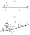
- An endoscope shown in Figure 4 to Figure 6 possesses a grip portion 9 which can be held with one hand and an insertion portion 21 extending forward from the grip portion 9.
- the grip portion 9 possesses an eyepiece portion 15 at its base end and a freely oscillating distal bending controlling portion 16 at its middle portion.
- a lighting apparatus 8 is unitedly arranged on the grip portion 9. That is to say, the lighting apparatus 8 is directly (without a cord having a light guide) attached to a rigid protruding branch portion 9a.
- the insertion portion 21 has appropriate flexibility and rigidity against pressure, and is provided with a distal portion 22 to be bent at its end which freely advances and curves as shown with an arrow A in Figure 4.
- an image guide, a light guide 3 (see Figure 6), a wire 17 for bending distal portion (see Figure 6), and a tube for working channel are inserted inside an outermost protecting tube (which outer diameter is arranged to be, for example, at least 5 mm).
- 23 indicates a working channel connection portion.
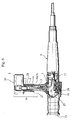
- the controlling portion 16 in a L-shaped or U-shaped configuration is fixed at a rotational axis 24. It is possible to rotate a wire reel 18 through a reduction gear 25 by oscillating the controlling portion 16, thereby the distal portion 22 to be bent at the end of the insertion portion 21 can be oscillated.
- the lighting apparatus 8 is provided with a lamp 2, a battery 1 (as a power source), and a tapered fiber 4 having a tapered configuration which diameter diminishes toward the end side.
- the lighting apparatus 8 protrudes from the grip portion 9 toward a direction that intersects perpendicularly with an axis of the grip portion 9. It is possible to arrange the lighting apparatus 8 to intersect the axis of the grip portion 9 at an angle besides 90° .
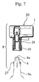
- the tapered fiber 4 is fixed inside the branch portion 9a which protrudes from the grip portion 9, and an incident end 4a having a big diameter appears outside under a detached situation shown in Figure 7.
- a male screw portion 27 is formed on an outer circumference of the end of the branch portion 9a, parts in the lighting apparatus 8 excluding the tapered fiber are stored in a casing 20, a cap nut 19 is arranged on an end of a protruding cylindrical portion 28, and the cap nut 19 fits unitedly and detachably with the male screw portion 27.
- the lighting apparatus 8 In order to arrange the lighting apparatus 8 unitedly on the grip portion 9 as shown in Figure 4 to Figure 7 for actual use as an endoscope, it is indispensable to diminish this lighting apparatus in size and weight and arrange an effective quantity of light to be incident from a base end face of the light guide 3, therefore the lighting apparatus 8 is composed as described below in the present invention.
- the lamp 2 as the light source is a (highly convergent) high luminance lamp of a low outgoing angle.
- the lamp 2 can be a lamp of any kind and any structure provided these conditions are satisfied, for example, a halogen lamp having a lens structure unitedly on an end portion of a lamp glass bulb.
- the tapered fiber 4 is applied between the lamp 2 and the base end face 3a of the light guide 3.
- the tapered fiber 4 is used to guide the outgoing light to the end with low-loss and increasing light density toward the light guide 3, and gradually diminishes in diameter toward the end side.
- a halogen lamp as the lamp 2, and a halogen lamp with an end lens of approximately 1 W to 10 W is suitable.
- This tapered fiber 4 is produced by (heating and) lengthening multicomponent glass fiber preform, and is arranged to be at least 0.4 in characteristic numerical aperture NA 0 is at least 0.4.
- 5 indicates a part of a light guide plug.
- the tapered fiber 4 is inserted into a base end side hole portion 6a of an axis hole 6 of the light guide plug 5 and fixed with adhesive, and an outgoing end 4b at an end of the tapered fiber 4 is inserted into a middle small diameter hole portion 6b of the axis hole 6.
- 7 is a cover of the light guide 3, and a base end portion of the cover 7 is inserted into an end side hole portion 6c of the light guide plug 5, a base end face of the light guide 3 which slightly appears and protrudes from the base end face of the cover 7 is inserted into the middle small diameter hole portion 6b and placed to face with the outgoing end 4b of the tapered fiber 4 closely or with a minute space.
- Figure 2 and Figure 3 are enlarged and simplified explanatory views illustrating a principal portion of Figure 1 or Figure 6, and as shown in Figure 2 and Figure 3, indicating an outer diameter of the incident end 4a (having a big diameter) of the tapered fiber 4 as D 1 , a numerical aperture of the incidence as NA 1 , an outer diameter of the outgoing end 4b as D 2 , a numerical aperture of the outgoing as NA 2 , an outer diameter of the light guide 3 as D 0 , and (as described above,) a characteristic numerical aperture of the tapered fiber 4 (which is determined by a refractive index between the core and the clad) as NA 0 , dimensions and characteristics of each portion are arranged satisfying the following numerical formula (1), numerical formula (2), and numerical formula (3).
- the battery 1 is used as the power source, the lithium battery is light, small, and has a long life, and the output voltage and current are stable, and these are advantages of the present invention. It is preferable to use a lithium battery of at most 10 V.
- the lamp 2 is a high luminance lamp of a low outgoing angle, and a halogen lamp with an end lens of approximately 1 W to 10 W (more preferably not exceeding 5 W) is suitable.
- a cordless endoscope composed as shown in Figure 4 to Figure 7 is arranged so that the endoscope can be easily carried, enlarges range of the operator to act and use the endoscope, and is convenient for diagnosis and medical treatment.
- the lighting apparatus 8 Provided a part or the whole of the lighting apparatus 8 is arranged to be detachable, it is possible to disassemble the endoscope and store it easily in a bag or a case when carrying the endoscope.
- the casing 20 where the battery 1 and the lamp 2 are stored is also detachable, therefore it is possible to detach the casing 20 and connect the endoscope to a stationary type lamp through an extension light guide cord and conduct stabilized observation.
- Figure 8A and Figure 8B show another embodiment of the present invention, and it is possible to change the endoscope from attached (connected) situation as shown in Figure 8A to a detached (separated) situation as shown in Figure 8B.
- a tapered fiber 4 is arranged at a casing (a lamp case) 20 side and is detached from a branch portion 9a of a grip portion 9 unitedly with a lamp 2 and a battery 1.
- a base end of the light guide 3 is arranged at an end of the branch portion 9a, and detachment is made through, for example, a cap nut 19.
- Table 1 A halogen lamp of 2.5 V and 1.7 W with characteristics shown in Table 1 was used as the lamp 2.
- the tapered fiber 4 is, with the core and the clad made of multicomponent glass, 0.62 in characteristic numerical aperture NA 0 , 3.6 mm in incident end diameter D 1 , 1.28 mm in outgoing end diameter, and 38 mm in length L.
- plastic fibers each of which is 0.5 in numerical aperture NA and 250 microns in outer diameter were used as the light guide 3.
- a lithium battery of 3 V was used as the battery 1.
- Table 2 shows results of measuring illuminance under the foregoing conditions.
- Table 2 Lighting Time (min.) Illuminance (lx) Distance from the Light Guide (mm) 0 mm 20 mm 40 mm 0 41,000 5,500 1,250 10 41,000 5,400 1,400 20 40,000 5,400 1,350 30 40,000 5,300 1,300
- the following is a measurement result of using a conventional example for comparison wherein a metal-halide lamp of 200 W was used as the light source.
- the total amount of luminescence luminous flux was 6250 lm, and when a light guide composed by seven plastic fibers of 250 microns (directly) received the luminescence luminous flux, in case the outer diameter of the light guide is 0.75 mm and the lighting area is 0.2 mm 2 (distance : 5 mm), the quantity of light becomes 4 lm ( lx / m 2 ), and the coupling efficiency B is extremely low as shown in the following numerical formula (5).
- the endoscope of the present invention is also preferable to use as a fiber scope for use in industrial application which is small, light, and handy to carry.
- the endoscope is easily handled and operated, and it is possible to carry the endoscope. Moreover, it is possible to insert the endoscope into a human body more easily, swiftly, accurately, and safely in medical examination or medical treatment.
- the endoscope is arranged to be small and light, and is handy to carry. Especially it is needless to store the battery 1 and the lamp 2 in the grip portion 9, therefore the grip portion 9 can be diminished in diameter, and this increases usability. It is possible to send approximately 5 to 10 percent of the forward total amount of luminous flux toward the light guide 3, the coupling efficiency is extremely improved, the power consumption is diminished, usage for long hours is possible, and sufficient illuminance is obtained.
- the light guide plug 5 connects the light guide 3 and the tapered fiber 4 with stability, and light of the light source lamp is effectively transmitted to the light guide. It is possible to connect this endoscope to a stationary type lamp through an extension light guide cord, therefore it is possible to obtain sufficient illuminance for hours and conduct stable observation using this endoscope.
Applications Claiming Priority (4)
| Application Number | Priority Date | Filing Date | Title |
|---|---|---|---|
| JP347795/95 | 1995-12-14 | ||
| JP7347795A JP2975302B2 (ja) | 1995-12-14 | 1995-12-14 | 内視鏡 |
| JP347794/95 | 1995-12-14 | ||
| JP7347794A JP2975301B2 (ja) | 1995-12-14 | 1995-12-14 | 光源装置 |
Publications (1)
| Publication Number | Publication Date |
|---|---|
| EP0781525A1 true EP0781525A1 (fr) | 1997-07-02 |
Family
ID=26578609
Family Applications (1)
| Application Number | Title | Priority Date | Filing Date |
|---|---|---|---|
| EP96119875A Withdrawn EP0781525A1 (fr) | 1995-12-14 | 1996-12-11 | Endoscope |
Country Status (2)
| Country | Link |
|---|---|
| US (1) | US5888194A (fr) |
| EP (1) | EP0781525A1 (fr) |
Cited By (1)
| Publication number | Priority date | Publication date | Assignee | Title |
|---|---|---|---|---|
| EP3146955A1 (fr) * | 2015-09-24 | 2017-03-29 | Hsiao-Sen Tseng | Aiguille optique avec rainure de guidage |
Families Citing this family (21)
| Publication number | Priority date | Publication date | Assignee | Title |
|---|---|---|---|---|
| US6921920B2 (en) * | 2001-08-31 | 2005-07-26 | Smith & Nephew, Inc. | Solid-state light source |
| US6692431B2 (en) | 2001-09-07 | 2004-02-17 | Smith & Nephew, Inc. | Endoscopic system with a solid-state light source |
| US20090185392A1 (en) * | 2003-03-26 | 2009-07-23 | Optim, Inc. | Detachable illumination system |
| US7229201B2 (en) * | 2003-03-26 | 2007-06-12 | Optim Inc. | Compact, high-efficiency, high-power solid state light source using a single solid state light-emitting device |
| US7798692B2 (en) * | 2003-03-26 | 2010-09-21 | Optim, Inc. | Illumination device |
| WO2006088938A1 (fr) * | 2005-02-15 | 2006-08-24 | Alcon, Inc. | Endo-illuminateur a haut rendement |
| CA2627180C (fr) * | 2005-10-31 | 2013-12-17 | Alcon, Inc. | Illuminateur chirurgical a angle large et variable |
| CA2674611A1 (fr) * | 2007-01-10 | 2008-07-17 | Optim, Inc. | Endoscope avec partie d'allongement detachable |
| EP2185291A2 (fr) * | 2007-07-17 | 2010-05-19 | Invista Technologies S.a.r.l. | Tricots et vêtements à couche de base fabriqués à partir de ceux-ci à propriétés de protection thermique améliorées |
| US20090190371A1 (en) * | 2008-01-24 | 2009-07-30 | Optim, Inc. | Monolithic illumination device |
| JP5198312B2 (ja) * | 2009-02-13 | 2013-05-15 | 富士フイルム株式会社 | ライトガイド、ライトガイドの製造方法、光源装置、及び内視鏡システム |
| JP2011224042A (ja) * | 2010-04-15 | 2011-11-10 | Fujifilm Corp | 光源装置及びこれを用いた内視鏡装置 |
| DK3228254T3 (da) | 2014-02-21 | 2020-03-23 | 3Dintegrated Aps | Sæt omfattende et kirurgisk instrument |
| JP6461665B2 (ja) * | 2015-03-24 | 2019-01-30 | Hoya株式会社 | 光源光学系及び光源装置 |
| CN106137107A (zh) * | 2015-03-31 | 2016-11-23 | 许云飞 | 尿道镜 |
| US11020144B2 (en) | 2015-07-21 | 2021-06-01 | 3Dintegrated Aps | Minimally invasive surgery system |
| WO2017012624A1 (fr) | 2015-07-21 | 2017-01-26 | 3Dintegrated Aps | Kit de montage de canule, kit de montage de trocart, ensemble manchon, système de chirurgie mini-invasive et procédé afférent |
| TW201713060A (zh) * | 2015-09-24 | 2017-04-01 | 曾效參 | 光導組件 |
| DK178899B1 (en) | 2015-10-09 | 2017-05-08 | 3Dintegrated Aps | A depiction system |
| WO2017075439A2 (fr) * | 2015-10-28 | 2017-05-04 | Acera LLC | Source de lumière mobile et portable |
| CN114271773A (zh) * | 2022-03-05 | 2022-04-05 | 深圳市三平影像科技有限公司 | 一种食道内视镜 |
Citations (6)
| Publication number | Priority date | Publication date | Assignee | Title |
|---|---|---|---|---|
| US3945371A (en) * | 1972-05-26 | 1976-03-23 | Stuart Lee Adelman | Apparatus for inspection and sampling in restricted aperture cavities employing fibre optics |
| EP0046238A1 (fr) * | 1980-08-07 | 1982-02-24 | Olympus Optical Co., Ltd. | Endoscope avec adaptateur |
| US4584988A (en) * | 1983-09-02 | 1986-04-29 | Olympus Optical Co., Ltd. | Illumination apparatus for endoscope |
| US5083549A (en) * | 1989-02-06 | 1992-01-28 | Candela Laser Corporation | Endoscope with tapered shaft |
| EP0573158A1 (fr) * | 1992-06-01 | 1993-12-08 | Citation Medical Corporation | Endoscope avec une source de lumière intérieure |
| US5309330A (en) * | 1993-01-11 | 1994-05-03 | Citation Medical Corporation | Light box |
Family Cites Families (10)
| Publication number | Priority date | Publication date | Assignee | Title |
|---|---|---|---|---|
| US2235979A (en) * | 1940-06-03 | 1941-03-25 | Albert L Brown | Surgical and diagnostic instrument |
| US3779628A (en) * | 1972-03-30 | 1973-12-18 | Corning Glass Works | Optical waveguide light source coupler |
| US4870952A (en) * | 1983-10-28 | 1989-10-03 | Miquel Martinez | Fiber optic illuminator for use in surgery |
| JPS61188509A (ja) * | 1985-02-16 | 1986-08-22 | Nippon Hoso Kyokai <Nhk> | 光結合装置 |
| US4729621A (en) * | 1985-03-11 | 1988-03-08 | Shiley Inc. | Integral optical fiber coupler |
| US5479545A (en) * | 1992-03-27 | 1995-12-26 | General Electric Company | Reverse flared optical coupling member for use with a high brightness light source |
| US5513291A (en) * | 1993-10-08 | 1996-04-30 | Origin Medsystems, Inc. | Light source modifications for plastic light fibre compatibility |
| US5554100A (en) * | 1994-03-24 | 1996-09-10 | United States Surgical Corporation | Arthroscope with shim for angularly orienting illumination fibers |
| US5746494A (en) * | 1994-11-22 | 1998-05-05 | Asahi Kogaku Kogyo Kabushiki Kaisha | Illuminating apparatus of endoscope |
| US5630783A (en) * | 1995-08-11 | 1997-05-20 | Steinberg; Jeffrey | Portable cystoscope |
-
1996
- 1996-12-11 EP EP96119875A patent/EP0781525A1/fr not_active Withdrawn
- 1996-12-12 US US08/764,781 patent/US5888194A/en not_active Expired - Fee Related
Patent Citations (6)
| Publication number | Priority date | Publication date | Assignee | Title |
|---|---|---|---|---|
| US3945371A (en) * | 1972-05-26 | 1976-03-23 | Stuart Lee Adelman | Apparatus for inspection and sampling in restricted aperture cavities employing fibre optics |
| EP0046238A1 (fr) * | 1980-08-07 | 1982-02-24 | Olympus Optical Co., Ltd. | Endoscope avec adaptateur |
| US4584988A (en) * | 1983-09-02 | 1986-04-29 | Olympus Optical Co., Ltd. | Illumination apparatus for endoscope |
| US5083549A (en) * | 1989-02-06 | 1992-01-28 | Candela Laser Corporation | Endoscope with tapered shaft |
| EP0573158A1 (fr) * | 1992-06-01 | 1993-12-08 | Citation Medical Corporation | Endoscope avec une source de lumière intérieure |
| US5309330A (en) * | 1993-01-11 | 1994-05-03 | Citation Medical Corporation | Light box |
Cited By (1)
| Publication number | Priority date | Publication date | Assignee | Title |
|---|---|---|---|---|
| EP3146955A1 (fr) * | 2015-09-24 | 2017-03-29 | Hsiao-Sen Tseng | Aiguille optique avec rainure de guidage |
Also Published As
| Publication number | Publication date |
|---|---|
| US5888194A (en) | 1999-03-30 |
Similar Documents
| Publication | Publication Date | Title |
|---|---|---|
| EP0781525A1 (fr) | Endoscope | |
| US7198397B2 (en) | LED endoscope illuminator and methods of mounting within an endoscope | |
| US8033704B2 (en) | Compact, high efficiency, high power solid state light source using a solid state light-emitting device | |
| EP1971888B1 (fr) | Dispositif d'éclairage | |
| US20070247867A1 (en) | Portable LED Light Source for an Endoscope or Boroscope | |
| US5139421A (en) | Mirror light | |
| US4823244A (en) | Light source assembly | |
| US4993945A (en) | Heated dental mirror | |
| US20100030033A1 (en) | Surgical light apparatus | |
| CN111031882B (zh) | 具有光源和光转换机构的照明设备 | |
| US5746494A (en) | Illuminating apparatus of endoscope | |
| US5348470A (en) | Fiber-optic illuminated dental mirror | |
| HU194057B (en) | Radiation device connected with reflector | |
| US20050043591A1 (en) | Otoscope | |
| JP3184151B2 (ja) | 携帯式内視鏡システム | |
| US11406252B2 (en) | Portable and sterilizable light source | |
| JP2975301B2 (ja) | 光源装置 | |
| JP2975302B2 (ja) | 内視鏡 | |
| JP3995878B2 (ja) | 内視鏡用光源装置 | |
| JPH1156777A (ja) | 簡易型内視鏡 | |
| JP3989678B2 (ja) | 内視鏡 | |
| JP4372915B2 (ja) | 内視鏡装置 | |
| US20060057535A1 (en) | Cordless intraoral dental examination instrument having non-plano mirror | |
| CN211741711U (zh) | 一种新型光学内窥镜成像及照明系统 | |
| JPH09154815A (ja) | 内視鏡装置 |
Legal Events
| Date | Code | Title | Description |
|---|---|---|---|
| PUAI | Public reference made under article 153(3) epc to a published international application that has entered the european phase |
Free format text: ORIGINAL CODE: 0009012 |
|
| AK | Designated contracting states |
Kind code of ref document: A1 Designated state(s): DE FR GB |
|
| 17P | Request for examination filed |
Effective date: 19970811 |
|
| 17Q | First examination report despatched |
Effective date: 20020118 |
|
| STAA | Information on the status of an ep patent application or granted ep patent |
Free format text: STATUS: THE APPLICATION IS DEEMED TO BE WITHDRAWN |
|
| 18D | Application deemed to be withdrawn |
Effective date: 20020529 |