EP0781044B1 - Appareil d'affichage d'images sur un tube à rayons cathodiques - Google Patents
Appareil d'affichage d'images sur un tube à rayons cathodiques Download PDFInfo
- Publication number
- EP0781044B1 EP0781044B1 EP96203525A EP96203525A EP0781044B1 EP 0781044 B1 EP0781044 B1 EP 0781044B1 EP 96203525 A EP96203525 A EP 96203525A EP 96203525 A EP96203525 A EP 96203525A EP 0781044 B1 EP0781044 B1 EP 0781044B1
- Authority
- EP
- European Patent Office
- Prior art keywords
- power supply
- voltage
- input
- comparator
- current
- Prior art date
- Legal status (The legal status is an assumption and is not a legal conclusion. Google has not performed a legal analysis and makes no representation as to the accuracy of the status listed.)
- Expired - Lifetime
Links
- 230000000694 effects Effects 0.000 description 7
- 235000021183 entrée Nutrition 0.000 description 7
- 230000007423 decrease Effects 0.000 description 3
- 230000001105 regulatory effect Effects 0.000 description 2
- 230000033228 biological regulation Effects 0.000 description 1
- 230000000593 degrading effect Effects 0.000 description 1
- 238000010586 diagram Methods 0.000 description 1
- 239000000284 extract Substances 0.000 description 1
- 230000005236 sound signal Effects 0.000 description 1
- 238000004804 winding Methods 0.000 description 1
Images

Classifications
-
- H—ELECTRICITY
- H04—ELECTRIC COMMUNICATION TECHNIQUE
- H04N—PICTORIAL COMMUNICATION, e.g. TELEVISION
- H04N5/00—Details of television systems
- H04N5/63—Generation or supply of power specially adapted for television receivers
-
- H—ELECTRICITY
- H04—ELECTRIC COMMUNICATION TECHNIQUE
- H04N—PICTORIAL COMMUNICATION, e.g. TELEVISION
- H04N3/00—Scanning details of television systems; Combination thereof with generation of supply voltages
- H04N3/10—Scanning details of television systems; Combination thereof with generation of supply voltages by means not exclusively optical-mechanical
- H04N3/16—Scanning details of television systems; Combination thereof with generation of supply voltages by means not exclusively optical-mechanical by deflecting electron beam in cathode-ray tube, e.g. scanning corrections
- H04N3/22—Circuits for controlling dimensions, shape or centering of picture on screen
- H04N3/223—Controlling dimensions
Definitions
- the present invention relates to a display device images, fitted with a cathode-ray screen tube, and including a circuit, called "power lines", generating on the one hand a current for the horizontal deviation of the cathode ray, and on the other hand a voltage called “very high voltage "required for the tube screen, a module feed specifically intended for feeding the power circuit lines and delivering a voltage adjustable, the value of which is controlled by a value of command, and an arrangement generating this value of control, essentially comprising a comparator, one of which first input is connected to a voltage source of reference, and having a second input to which a fraction of the above adjustable voltage, said fraction of the adjustable tension being formed by means of a divider resistive made of a first branch called “head” which is connected between, on the one hand the power supply module and secondly the second comparator input, and a second branch called “foot” which is connected between, on the one hand the second comparator input, and on the other share a reference voltage.
- a circuit called "
- a regulated power supply with a current limitation titled “Overload protection for series regulator”, is presented on page 594 of the book “Sourcebook of electronic circuits ", by John Markus, Mac Graw Hill, 1968.
- This power supply has a current limitation which is carried out by a circuit, distinct from the circuit of voltage regulation, which only comes into play at above a predetermined current threshold.
- An object of the invention is to suppress resistance about ten ohms, because it permanently dissipates a significant power.
- the line power circuit is connected to a socket on said resistive divider, in such a way that the supply current of the power circuit lines crosses part of the divider.
- the invention is therefore based on the idea of degrading voluntarily the device's regulatory performance which produces the supply voltage of the circuit power lines, so as to have the same effect as if a resistance of ten ohms was placed in the power connection. Although it produces the same effect that the resistance of ten ohms of art anterior, the resistance part which is crossed by the power supply line power circuit has a value of only a fraction of an ohm, which provides power saving.
- the part of the resistive divider that the circuit supply current power lines crosses, is part of the branch of divider head, and a fixed voltage source is connected, to generate the reference voltage, between, on the one hand the output of the power supply module delivering a adjustable voltage, and on the other hand the first input of the comparator.
- Figure 1 shows schematically an apparatus image display with a beam screen tube cathodic.
- FIG. 2 schematically represents a first mode of realization of a device which produces a tension supply for a power circuit lines.
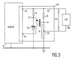
- FIG. 3 schematically represents a second mode making a device that produces a voltage supply for a power circuit lines.
- the invention will be described with reference to a television, but it applies equally well to any display device images, for example to a monitor.
- the television whose diagram is represented on the figure 1 includes a tuner 22 receiving a signal for example of an antenna 21 and transposing its frequency towards intermediate frequencies intended for an amplifier with video intermediate frequency 23 and an amplifier at intermediate frequency its 24 which follow it.
- the sound intermediate frequency amplifier 24 is followed a demodulator 29 which delivers the audio signals in band basic to an audio power amplifier 27, powering a speaker 33.
- the frequency amplifier video intermediary 23 is followed by a unit 25 which provides a baseband video signal to a video amplifier 26 delivering ad-hoc signals to the electrodes of a screen tube 32 with cathode beam.
- Unit 25 also extracts signal synchronization signals which are fed to a circuit frame scanning circuit 28 and to a line scanning circuit 36.
- the frame scanning circuit 28 delivers a current in a frame deflection winding 30.
- Line scan circuit is fitted with a power unit for lines 35 which delivers a current in a line deflection coil 34, and produces a so-called "very high voltage" voltage, of around 25 kV, for supply the screen to the screen tube, to which it is connected by a connection 31.
- the power circuit lines 35 is supplied via a connection 5, by a specific module supply 14, itself supplied by a supply General 2, connected to the sector.
- the other circuits 22-29 are fed, as usual, from the floor power lines 35, by connections not shown to simplify the figure.
- the power circuit connection 5 of the power circuit 35 lines is connected to a socket 12 of resistor 8. From this fact, part of this resistance 8 is crossed by the supply current of the power circuit lines.
- FIG. 3 A neighboring device is represented by FIG. 3.
- most of the elements are identical to those of Figure 2, including power supply 2, the circuit power lines 35, transistor 1, the first and the second input 3 and 4 of the comparator.
- the difference between the assembly of Figure 3 and that of Figure 2 fits in the the zener diode 13 is now connected between the point 3 and ground, and that the power circuit lines is connected on the positive side directly to terminal 10, and to the mass via part of the resistor 6, by a plug 12.
- the resistor 6 is partly crossed by the supply current of the power circuit lines.
- the resistor 11 which allows the passage of a current in the zener diode is connected between terminal 10 of the module power supply and the emitter of transistor 1.
- the device of FIG. 2 is however preferred because that the lines power circuit is connected to it directly to ground.
- the indication of some numerical values, in reference in Figure 2, will highlight why the same effect as if a ten ohm resistor were placed in the power connection, is obtained.
- the zener diode 13 is for example a "5V2" model, which provides a voltage 5.2 volts. Going from point 10 to point 4 via the diode 13, we meet, in cascade, the zener tension 13 and the emitter-base voltage of transistor 1, which provides about 6 volts. This tension is also present in resistance 8 terminals. If the desired voltage at point 10 is 96 volts, for example, so there must be 6 volts across resistor 8, and 90 volts across the resistor 6.
- the voltage across resistor 8 is sort of multiplied by the ratio between the resistors 6 + 8 and: 8, due to the error voltage applied to input 9 of circuit 14.
- the induced tension by the passage of the supply current of the circuit power lines in part of resistor 8 is, also multiplied by the ratio between the resistances 6 + 8 and 8, and provides the same effect as a resistance of ten ohms placed in the power connection between the point 12 and circuit 35, although the top part of the resistor 8 has a value of about 0.6 ohms, i.e. 10 ⁇ ⁇ 6/96.
- a line power circuit consumes, for example in the case of a 110 ° screen tube of average dimensions, under 96 volts, about 700 milliamps, which dissipates about five watts into a 10 ohm resistor. These five watts are saved with the assembly according to the invention.
Landscapes
- Engineering & Computer Science (AREA)
- Multimedia (AREA)
- Signal Processing (AREA)
- Details Of Television Scanning (AREA)
- Direct Current Feeding And Distribution (AREA)
- Television Receiver Circuits (AREA)
Applications Claiming Priority (2)
| Application Number | Priority Date | Filing Date | Title |
|---|---|---|---|
| FR9515176A FR2742921A1 (fr) | 1995-12-20 | 1995-12-20 | Appareil d'affichage d'images sur un tube a rayons cathodiques |
| FR9515176 | 1995-12-20 |
Publications (2)
| Publication Number | Publication Date |
|---|---|
| EP0781044A1 EP0781044A1 (fr) | 1997-06-25 |
| EP0781044B1 true EP0781044B1 (fr) | 2001-09-12 |
Family
ID=9485733
Family Applications (1)
| Application Number | Title | Priority Date | Filing Date |
|---|---|---|---|
| EP96203525A Expired - Lifetime EP0781044B1 (fr) | 1995-12-20 | 1996-12-12 | Appareil d'affichage d'images sur un tube à rayons cathodiques |
Country Status (6)
| Country | Link |
|---|---|
| US (1) | US5804929A (enExample) |
| EP (1) | EP0781044B1 (enExample) |
| JP (1) | JPH09200562A (enExample) |
| KR (1) | KR100421324B1 (enExample) |
| DE (1) | DE69615139T2 (enExample) |
| FR (1) | FR2742921A1 (enExample) |
Families Citing this family (1)
| Publication number | Priority date | Publication date | Assignee | Title |
|---|---|---|---|---|
| JP2004515124A (ja) * | 2000-11-22 | 2004-05-20 | コーニンクレッカ フィリップス エレクトロニクス エヌ ヴィ | 電源 |
Family Cites Families (5)
| Publication number | Priority date | Publication date | Assignee | Title |
|---|---|---|---|---|
| US4414494A (en) * | 1981-04-06 | 1983-11-08 | Electrohome Limited | Regulation of the scan width of a raster scanned CRT deflection system |
| US4714871A (en) * | 1986-12-18 | 1987-12-22 | Rca Corporation | Level shifter for a power supply regulator in a television apparatus |
| US5034667A (en) * | 1990-04-13 | 1991-07-23 | Thomson Consumer Electronics, Inc. | Raster size regulating circuit |
| GB9114354D0 (en) * | 1991-07-03 | 1991-08-21 | Thompson Consumer Electronics | Run/standby control with switched mode power supply |
| GB9116616D0 (en) * | 1991-08-01 | 1991-09-18 | Thomson Consumer Electronics | Switched mode power supply with startup precharge |
-
1995
- 1995-12-20 FR FR9515176A patent/FR2742921A1/fr not_active Withdrawn
-
1996
- 1996-12-09 US US08/762,623 patent/US5804929A/en not_active Expired - Fee Related
- 1996-12-12 EP EP96203525A patent/EP0781044B1/fr not_active Expired - Lifetime
- 1996-12-12 DE DE69615139T patent/DE69615139T2/de not_active Expired - Fee Related
- 1996-12-17 JP JP8336826A patent/JPH09200562A/ja active Pending
- 1996-12-18 KR KR1019960067175A patent/KR100421324B1/ko not_active Expired - Fee Related
Also Published As
| Publication number | Publication date |
|---|---|
| EP0781044A1 (fr) | 1997-06-25 |
| DE69615139T2 (de) | 2002-06-20 |
| JPH09200562A (ja) | 1997-07-31 |
| DE69615139D1 (de) | 2001-10-18 |
| KR970057617A (ko) | 1997-07-31 |
| FR2742921A1 (fr) | 1997-06-27 |
| KR100421324B1 (ko) | 2004-10-08 |
| US5804929A (en) | 1998-09-08 |
Similar Documents
| Publication | Publication Date | Title |
|---|---|---|
| JPH0153555B2 (enExample) | ||
| JP2899680B2 (ja) | ビデオ表示装置及び該装置を制御する方法 | |
| EP0781044B1 (fr) | Appareil d'affichage d'images sur un tube à rayons cathodiques | |
| JPS5990473A (ja) | ビデオ信号処理装置における自動バイアス制御装置 | |
| FR2538201A1 (fr) | Regulateur de l'alimentation d'un televiseur repondant aux changements de courant des faisceaux | |
| EP0506186B1 (fr) | Dispositif amplificateur vidéo | |
| EP0781043B1 (fr) | Appareil d'affichage d'images sur un tube écran, muni d'une alimentation à découpage auto-oscillante | |
| JPH08279996A (ja) | 周囲光状態を指示し制御する回路装置 | |
| US6188444B1 (en) | Apparatus and methods for synthesizing foreground and background images | |
| EP0649248B1 (fr) | Appareil d'affichage d'images avec modulation de vitesse du spot | |
| EP0353808B1 (fr) | Circuit de compensation de courant | |
| EP0055152B1 (fr) | Circuit de balayage vertical, alimentation pour sa commande, et récepteur de télévision comportant un tel circuit | |
| US5426394A (en) | Sound intermediate frequency amplifier for a broadcast receiver | |
| US4870331A (en) | Circuit arrangement for a picture display device for the stabilization of the size of the picture displayed | |
| JP2586851B2 (ja) | 液晶テレビ | |
| FR2726706A1 (fr) | Dispositif de generation de fonctions de transfert definies par intervalles | |
| EP0151080B1 (fr) | Circuit de transposition de niveau utilisable pour imagerie vidéo à haute définition | |
| KR940005338Y1 (ko) | 피드백 앰프를 이용한 클램프 회로 | |
| JP3660062B2 (ja) | アナログブランキングパルス発生回路 | |
| JP3245896B2 (ja) | 発振周波数制御回路 | |
| EP0285200A1 (fr) | Circuit de balayage ligne et de génération de tension | |
| FR2744583A1 (fr) | Appareil d'affichage d'images, muni d'un dispositif de mise en veille progressif | |
| JPH0546105A (ja) | 画質制御装置 | |
| JP2501568Y2 (ja) | 受像機 | |
| EP0851646A1 (fr) | Appareil téléphonique à compensation de pertes en ligne |
Legal Events
| Date | Code | Title | Description |
|---|---|---|---|
| PUAI | Public reference made under article 153(3) epc to a published international application that has entered the european phase |
Free format text: ORIGINAL CODE: 0009012 |
|
| AK | Designated contracting states |
Kind code of ref document: A1 Designated state(s): DE ES FR GB IT |
|
| RAP1 | Party data changed (applicant data changed or rights of an application transferred) |
Owner name: PHILIPS ELECTRONICS N.V. Owner name: PHILIPS ELECTRONIQUE GRAND PUBLIC |
|
| 17P | Request for examination filed |
Effective date: 19971229 |
|
| RAP1 | Party data changed (applicant data changed or rights of an application transferred) |
Owner name: KONINKLIJKE PHILIPS ELECTRONICS N.V. |
|
| GRAG | Despatch of communication of intention to grant |
Free format text: ORIGINAL CODE: EPIDOS AGRA |
|
| 17Q | First examination report despatched |
Effective date: 20000831 |
|
| GRAG | Despatch of communication of intention to grant |
Free format text: ORIGINAL CODE: EPIDOS AGRA |
|
| GRAH | Despatch of communication of intention to grant a patent |
Free format text: ORIGINAL CODE: EPIDOS IGRA |
|
| GRAH | Despatch of communication of intention to grant a patent |
Free format text: ORIGINAL CODE: EPIDOS IGRA |
|
| GRAA | (expected) grant |
Free format text: ORIGINAL CODE: 0009210 |
|
| AK | Designated contracting states |
Kind code of ref document: B1 Designated state(s): DE ES FR GB IT |
|
| REF | Corresponds to: |
Ref document number: 69615139 Country of ref document: DE Date of ref document: 20011018 |
|
| REG | Reference to a national code |
Ref country code: GB Ref legal event code: IF02 |
|
| GBT | Gb: translation of ep patent filed (gb section 77(6)(a)/1977) |
Effective date: 20011211 |
|
| RIN2 | Information on inventor provided after grant (corrected) |
Free format text: DECRAEMER, ALAIN |
|
| PG25 | Lapsed in a contracting state [announced via postgrant information from national office to epo] |
Ref country code: ES Free format text: LAPSE BECAUSE OF FAILURE TO SUBMIT A TRANSLATION OF THE DESCRIPTION OR TO PAY THE FEE WITHIN THE PRESCRIBED TIME-LIMIT Effective date: 20020326 |
|
| PLBE | No opposition filed within time limit |
Free format text: ORIGINAL CODE: 0009261 |
|
| STAA | Information on the status of an ep patent application or granted ep patent |
Free format text: STATUS: NO OPPOSITION FILED WITHIN TIME LIMIT |
|
| 26N | No opposition filed | ||
| REG | Reference to a national code |
Ref country code: GB Ref legal event code: 746 Effective date: 20020919 |
|
| REG | Reference to a national code |
Ref country code: FR Ref legal event code: D6 |
|
| PGFP | Annual fee paid to national office [announced via postgrant information from national office to epo] |
Ref country code: GB Payment date: 20041222 Year of fee payment: 9 |
|
| PGFP | Annual fee paid to national office [announced via postgrant information from national office to epo] |
Ref country code: FR Payment date: 20041228 Year of fee payment: 9 |
|
| PGFP | Annual fee paid to national office [announced via postgrant information from national office to epo] |
Ref country code: DE Payment date: 20050215 Year of fee payment: 9 |
|
| PG25 | Lapsed in a contracting state [announced via postgrant information from national office to epo] |
Ref country code: IT Free format text: LAPSE BECAUSE OF NON-PAYMENT OF DUE FEES Effective date: 20051212 Ref country code: GB Free format text: LAPSE BECAUSE OF NON-PAYMENT OF DUE FEES Effective date: 20051212 |
|
| PG25 | Lapsed in a contracting state [announced via postgrant information from national office to epo] |
Ref country code: DE Free format text: LAPSE BECAUSE OF NON-PAYMENT OF DUE FEES Effective date: 20060701 |
|
| GBPC | Gb: european patent ceased through non-payment of renewal fee |
Effective date: 20051212 |
|
| PG25 | Lapsed in a contracting state [announced via postgrant information from national office to epo] |
Ref country code: FR Free format text: LAPSE BECAUSE OF NON-PAYMENT OF DUE FEES Effective date: 20060831 |
|
| REG | Reference to a national code |
Ref country code: FR Ref legal event code: ST Effective date: 20060831 |