EP0780709B1 - Broadband coupler - Google Patents
Broadband coupler Download PDFInfo
- Publication number
- EP0780709B1 EP0780709B1 EP96309193A EP96309193A EP0780709B1 EP 0780709 B1 EP0780709 B1 EP 0780709B1 EP 96309193 A EP96309193 A EP 96309193A EP 96309193 A EP96309193 A EP 96309193A EP 0780709 B1 EP0780709 B1 EP 0780709B1
- Authority
- EP
- European Patent Office
- Prior art keywords
- fibers
- fiber
- optical
- coupler
- optical fibers
- Prior art date
- Legal status (The legal status is an assumption and is not a legal conclusion. Google has not performed a legal analysis and makes no representation as to the accuracy of the status listed.)
- Expired - Lifetime
Links
- 239000000835 fiber Substances 0.000 claims description 190
- 239000013307 optical fiber Substances 0.000 claims description 38
- 238000000034 method Methods 0.000 claims description 18
- 238000010438 heat treatment Methods 0.000 claims description 12
- 230000004927 fusion Effects 0.000 claims description 3
- 230000003287 optical effect Effects 0.000 description 13
- 238000003780 insertion Methods 0.000 description 9
- 230000037431 insertion Effects 0.000 description 9
- 239000011521 glass Substances 0.000 description 7
- 238000004519 manufacturing process Methods 0.000 description 6
- 230000008569 process Effects 0.000 description 5
- 230000004044 response Effects 0.000 description 5
- 238000010168 coupling process Methods 0.000 description 4
- 230000009467 reduction Effects 0.000 description 4
- 230000003595 spectral effect Effects 0.000 description 4
- 239000000872 buffer Substances 0.000 description 3
- 230000008859 change Effects 0.000 description 3
- 238000005253 cladding Methods 0.000 description 3
- 238000000576 coating method Methods 0.000 description 3
- 230000008878 coupling Effects 0.000 description 3
- 238000005859 coupling reaction Methods 0.000 description 3
- 230000001681 protective effect Effects 0.000 description 3
- VYPSYNLAJGMNEJ-UHFFFAOYSA-N Silicium dioxide Chemical compound O=[Si]=O VYPSYNLAJGMNEJ-UHFFFAOYSA-N 0.000 description 2
- 230000033001 locomotion Effects 0.000 description 2
- 230000002411 adverse Effects 0.000 description 1
- 230000004075 alteration Effects 0.000 description 1
- 230000005540 biological transmission Effects 0.000 description 1
- 230000001627 detrimental effect Effects 0.000 description 1
- 230000006698 induction Effects 0.000 description 1
- 239000000463 material Substances 0.000 description 1
- 230000013011 mating Effects 0.000 description 1
- 238000012986 modification Methods 0.000 description 1
- 230000004048 modification Effects 0.000 description 1
- 230000010287 polarization Effects 0.000 description 1
- 230000001902 propagating effect Effects 0.000 description 1
- 239000000377 silicon dioxide Substances 0.000 description 1
- 238000001228 spectrum Methods 0.000 description 1
- 239000000758 substrate Substances 0.000 description 1
- 238000004804 winding Methods 0.000 description 1
Images



Classifications
-
- G—PHYSICS
- G02—OPTICS
- G02B—OPTICAL ELEMENTS, SYSTEMS OR APPARATUS
- G02B6/00—Light guides; Structural details of arrangements comprising light guides and other optical elements, e.g. couplings
- G02B6/24—Coupling light guides
- G02B6/26—Optical coupling means
- G02B6/28—Optical coupling means having data bus means, i.e. plural waveguides interconnected and providing an inherently bidirectional system by mixing and splitting signals
- G02B6/2804—Optical coupling means having data bus means, i.e. plural waveguides interconnected and providing an inherently bidirectional system by mixing and splitting signals forming multipart couplers without wavelength selective elements, e.g. "T" couplers, star couplers
- G02B6/2856—Optical coupling means having data bus means, i.e. plural waveguides interconnected and providing an inherently bidirectional system by mixing and splitting signals forming multipart couplers without wavelength selective elements, e.g. "T" couplers, star couplers formed or shaped by thermal heating means, e.g. splitting, branching and/or combining elements
-
- G—PHYSICS
- G02—OPTICS
- G02B—OPTICAL ELEMENTS, SYSTEMS OR APPARATUS
- G02B6/00—Light guides; Structural details of arrangements comprising light guides and other optical elements, e.g. couplings
- G02B6/24—Coupling light guides
- G02B6/26—Optical coupling means
- G02B6/28—Optical coupling means having data bus means, i.e. plural waveguides interconnected and providing an inherently bidirectional system by mixing and splitting signals
- G02B6/2804—Optical coupling means having data bus means, i.e. plural waveguides interconnected and providing an inherently bidirectional system by mixing and splitting signals forming multipart couplers without wavelength selective elements, e.g. "T" couplers, star couplers
- G02B6/2821—Optical coupling means having data bus means, i.e. plural waveguides interconnected and providing an inherently bidirectional system by mixing and splitting signals forming multipart couplers without wavelength selective elements, e.g. "T" couplers, star couplers using lateral coupling between contiguous fibres to split or combine optical signals
- G02B6/2835—Optical coupling means having data bus means, i.e. plural waveguides interconnected and providing an inherently bidirectional system by mixing and splitting signals forming multipart couplers without wavelength selective elements, e.g. "T" couplers, star couplers using lateral coupling between contiguous fibres to split or combine optical signals formed or shaped by thermal treatment, e.g. couplers
-
- G—PHYSICS
- G02—OPTICS
- G02B—OPTICAL ELEMENTS, SYSTEMS OR APPARATUS
- G02B6/00—Light guides; Structural details of arrangements comprising light guides and other optical elements, e.g. couplings
- G02B6/24—Coupling light guides
- G02B6/26—Optical coupling means
- G02B6/28—Optical coupling means having data bus means, i.e. plural waveguides interconnected and providing an inherently bidirectional system by mixing and splitting signals
- G02B6/2804—Optical coupling means having data bus means, i.e. plural waveguides interconnected and providing an inherently bidirectional system by mixing and splitting signals forming multipart couplers without wavelength selective elements, e.g. "T" couplers, star couplers
- G02B6/2821—Optical coupling means having data bus means, i.e. plural waveguides interconnected and providing an inherently bidirectional system by mixing and splitting signals forming multipart couplers without wavelength selective elements, e.g. "T" couplers, star couplers using lateral coupling between contiguous fibres to split or combine optical signals
- G02B6/2826—Optical coupling means having data bus means, i.e. plural waveguides interconnected and providing an inherently bidirectional system by mixing and splitting signals forming multipart couplers without wavelength selective elements, e.g. "T" couplers, star couplers using lateral coupling between contiguous fibres to split or combine optical signals using mechanical machining means for shaping of the couplers, e.g. grinding or polishing
Definitions
- the present invention relates generally to couplers for optical fibers, and more particularly to fiber optic splitters operable over a broadband of wavelengths.
- Fiber optics are widely used in many diverse applications, including telecommunication systems, instrumentation and sensing operations.
- An example of such an application is a multi-access optical telecommunications network.
- optical fiber connects a number of users or subscribers to a central office using passive couplers. This type of network is particularly attractive since there are typically no active optical devices located outside of the central office or subscriber locations.
- An optical fiber typically includes an inner core region surrounded by an outer cladding made of a similar material.
- the inner core has a relatively higher index of refraction than the cladding, resulting in total internal reflection of the light beam within the core. This results in very efficient transmission of light through the core.
- Light may be transferred or split between separate fibers through the use of a fiber optic coupler.
- One extensively used type of fiber optic coupler is a fused biconically tapered (FBT) coupler.
- FBT fused biconically tapered
- the basic optical performance of fiber optic couplers can be described by three fundamental quantities: excess loss, insertion loss and uniformity.
- the excess loss expressed in decibels (dB) is a measure of how much light or optical energy is lost in the coupling process.
- Excess loss is defined as the ratio of the total output power to the amount of optical power launched into the input fiber of the coupler.
- the ratio of the optical power in one of the output fibers relative to the input optical power is known as the insertion loss.
- the insertion loss is also often expressed in decibels.
- Another term often used to characterize the optical performance of couplers is uniformity. Uniformity is a measure of the spread in the insertion losses of the coupler. It is also expressed in decibels and is defined as the difference between the maximum and minimum values of insertion loss.
- Fiber optic couplers in use today are designed to operate effectively over only a narrow range or "window" of wavelengths.
- the most common wavelengths of interest for telecommunication applications are those centered around 1310 nm and 1550 nm.
- These fiber optic couplers often called single window couplers, essentially provide equal splitting of light from one or more input fibers to a number of output fibers at a preselected wavelength.
- the insertion loss of each output port for such a single window coupler changes as a function of the wavelength of the transmitted light.
- the optical power in the output fibers i.e., insertion loss
- This behavior typically limits the use of such single window couplers to within ⁇ 20 nm of the center of the wavelength window.
- broadband fiber optic couplers which exhibit a relatively constant insertion loss over a broad range of wavelengths, are required.
- 2x4 couplers have been fabricated by concatenating three 1x2 or 2x2 couplers to form the desired configuration.
- the resulting tree structure has a fairly large package size, which can be a problem when the space allotted for the coupler is limited.
- Document WO9513554 discloses a fused fiber optic 1x4 or 2x4 coupler and a method of producing the same.
- the fibers are located such that their cores are centered at the corners of a four-sided polygon. During the manufacturing process of the coupler all four fibers are heated and drawn simultaneously.
- the present invention overcomes these and other problems and provides a method for producing a 2x4 broadband coupler, which utilizes two fiber diameters, and provides a coupler which is easier to manufacture and which has improved operating characteristics.
- a method of forming a broadband fiber optic coupler comprising four optical fibers, characterised by the steps of: a) initially arranging a first optical fiber and a second optical fiber of substantially the same diameters side-by-side; b) then bringing said first and second optical fibers together into intimate contact with each other; c) subsequently simultaneously heating and tensioning said fibers together until said first and second optical fibers fuse together, said two fibers forming grooves along opposite sides of said the line of fusion; d) then positioning a third optical fiber in intimate contact with said first and second optical fibers within one of the grooves formed by said first and second optical fibers, and positioning a fourth optical fiber in intimate contact with said first and second optical fibers within the other groove formed by said optical fibers; and e) finally heating, elongating and fusing said optical fibers together to achieve a broadband coupler.
- a fiber optic coupler may be provided as described above which utilizes only two fiber diameters.
- the fiber optic coupler as described above can have a flatter spectral response than optical devices utilizing three fiber diameters.
- the fiber optic coupler as described above may be operable over a wider range of wavelengths.
- a fiber optic coupler as described above which can be used as a 1x4 coupler or a 2x4 coupler.
- the method of producing couplers as described above may require only one fiber reduction.
- the method as described above is consistent and repeatable.
- FIGS. 1-6 illustrate a method of fabricating a 2x4 broadband fiber optic coupler in accordance with the present invention.
- four lengths of single mode optical fiber are stripped of all protective buffers and coatings so as to expose a region of bare glass for a length of approximately 2.54 cm (1 inch).
- the exposed regions of two of the four fibers, designated 1 and 2 in the drawings, are brought together side-by-side, as shown in FIGS. 1 and 2.
- all optical fibers are shown without protective buffers or coatings, and one end of the fibers is shown sectioned to illustrate generally the core and cladding of each optical fiber.
- fibers 1 and 2 are carefully wrapped over each other several times to join one to the other and thereby create a "wrapped fiber zone.”
- the phrase “wrapped fiber zone” refers to the lengths of the exposed region of fibers 1,2 which are wrapped relative to each other.
- FIG. 2 illustrates a portion of the wrapped fiber zone.
- fiber 1 is wrapped around fiber 2 and the respective fibers have moved 180° from their original positions relative to a line of contact designated "A,” as best illustrated in FIGS. 8A-8C.
- FIG. 8E illustrates the position of fibers 1, 2 where fibers 1, 2 have been wrapped completely, i.e., have moved 360° from their initial positions.
- one "wrap" shall be defined as the change in position of fibers 1, 2, as illustrated in FIGS. 8A-8E.
- fibers 1 and 2 in the "wrapped fiber zone” include at least one "wrap” (i.e., one 360° spiral). It is important to note that fibers 1 and 2 are carefully “wrapped” relative to one another (as contrasted with “twisting” the two fibers) so as to avoid introducing any internal torsional stress in fibers 1, 2 which may adversely affect the polarization properties of light propagating therethrough. In other words, twisting of the individual fibers is to be avoided because of the detrimental effect such twisting has on the optical properties of fibers 1, 2. In this respect, the desired "wrapping" of fibers 1 and 2 should not be accomplished by clamping the ends thereof and twisting them about a central axis.
- FIGS. 8A-8E show the relative position of fibers 1, 2 at various spaced apart locations along one "wrap.”
- fibers 1, 2 When fibers 1, 2 are pulled taut, a continuous line of contact is formed between fibers 1 and 2.
- fibers 1, 2 would be arranged in such a manner so as to produce a line of contact along a straight linear axis.
- the line of contact between fibers 1 and 2 is not along an exact, true “straight line” or "axis,” but rather is along a line which is curvilinear, having a contour which may best be described as helical with an extremely gentle pitch. Accordingly, as used herein, the term “line” is intended to describe a line which may be straight or curvilinear. Accordingly, when fibers 1, 2 are pulled taut, a line of contact is formed in the wrapped fiber zone.
- the line of contact designated "A" in the drawing, is generally straight or curvilinear.
- a gas flame designated 20 in FIG. 3, is used to provide the necessary heat.
- Fibers 1, 2 may also be heated by laser energy, induction heating or any other heating means, without deviating from the present invention.
- Flame 20 is applied to the exposed region of glass of fibers 1, 2 to soften same. As illustrated in FIG. 3, flame 20 is moved along fibers 1, 2 along a portion of the wrapped fibers 1, 2. While flame 20 moves along fibers 1, 2, they are slowly pulled axially from one direction.
- Fibers 1, 2 are axially pulled as schematically represented by arrow "P" in FIG. 3 in order to stretch fibers 1, 2 and reduce their diameters.
- the heated sections of fibers 1, 2 have a constant yet reduced diameter over the length of the wrapped fibers 1, 2 scanned by flame 20.
- the final diameter of fibers 1, 2 in the heated region is controlled by the length to which fibers 1, 2 are stretched. It is important to note that a uniform relative motion between fibers 1, 2 and flame 20 is required to obtain constant fiber diameters along the heated sections of fibers 1, 2.
- the method of reducing the fibers as heretofore described is discussed in U.S. Letters Patent No. 4,798,438, the disclosure of which is incorporated herein by reference.
- Axial force "P" exerted on fibers 1, 2, also ensures that fibers 1, 2 remain in contact during the heating of the fibers.
- the actual reduction in size of fibers 1, 2 is relatively slight.
- the length of fibers 1, 2 are stretched such that the actual reduction in the diameter of fibers 1, 2 is less than 10%, and more preferably about 5%.
- the resulting diameters of fibers 1, 2 as shown in FIGS. 3-7 are noticeably smaller than the original diameters of fibers 1, 2 shown in FIG. 2 and smaller than the diameters of fibers 3, 4 in FIGS. 4-6. This exaggeration is merely to indicate that a change in the diameter exists, and is not intended to represent the actual relative change.
- the heating and pulling of the two contacting fibers 1, 2 fuses fibers 1, 2 together into a single twin-fiber structure along the heated length as a result of the softening of the glass. Also, it is important that the wrapping of fibers 1, 2 produces continuous linear contact between fibers 1, 2 when fibers 1, 2 are pulled taut. The resulting twin-fiber structure is therefore fused together along a line of contact. Wrapped and fused fibers 1, 2 produce grooves or recesses 13, 14 formed on opposite sides of the fused fibers 1, 2. These diametrically opposed grooves or recesses 13, 14 spiral along a generally helical path around the line of contact of the fused fibers 1, 2.
- a third fiber 3 is wrapped about fused fibers 1, 2, as schematically shown in FIGS. 4 and 9..
- Third fiber 3 is positioned to one side of fused fibers 1, 2 within helical groove 13.
- Third fiber 3 is assembled with fused fibers 1, 2 basically by winding it in the same direction of wrap as fused fibers 1, 2.
- Third fiber 3 is then pulled taut at its axial ends to cause it to seat or nest itself into groove 13, ensuring contact with both fibers 1, 2.
- the axial force pulling third fiber 3 taut produces radial forces directed toward fibers 1, 2.
- a fourth fiber 4 is similarly positioned to the side of the fused fibers 1, 2 within groove 14 and is wrapped around the now three-fiber bundle. Again, it is important to ensure that fourth fiber 4 is wrapped around fused fibers 1, 2 in the same wrap direction as is initially introduced to fused fibers 1, 2. Again, by pulling the end of fourth fiber 4 in an axial direction, radial forces are exerted on fourth fiber 4 causing it to seat itself in groove 14, thereby ensuring contact with both fibers.
- the four-fiber bundle is then heated, as schematically illustrated in FIG. 6, with sufficient heat to soften the glass.
- Heat source 20 preferably oscillates back and forth parallel to the fiber bundle.
- Fibers 1-4 are pulled simultaneously from both sides while light is launched into one of the original fused fibers 1, 2.
- the light exiting each of the four output ports (fibers) is monitored using a photodetector (not shown).
- a photodetector not shown.
- the heating and stretching of fibers 1-4 is then terminated.
- the heating and elongation process thus produces a drawn fused tapered coupling region, as schematically shown in FIG. 7, which may then be attached to a silica substrate or other support surface (not shown).
- FIGS. 12 and 13 The broadband performance of a 2x4 coupler fabricated in accordance with the present invention is illustrated in FIGS. 12 and 13.
- the test data were obtained by injecting white light into launch fibers 1 and 2 and scanning the outputs of fibers 1, 2, 3 and 4 with an optical spectrum analyzer.
- the maximum insertion losses of the coupler were less than 7.5 dB over the extended wavelength range of 1250 nm to 1600 nm.
- the uniformity of the four outputs was less than 2 dB.
- the 2x4 coupler exhibits uniform and broadband coupling over an extended range of wavelengths.
- the nearly identical behavior of the coupler when light is launched into fibers 1 and 2 clearly demonstrates the ability of the coupler to function as either a 1x4 or 2x4 splitter.
- the present invention also offers advantages over other methods resulting in an easier, more reliable and reproducible method of fabrication.
- FIG. 10 shows two lengths of optical fiber, designated 101, 102.
- Fibers 101, 102 are stripped of all protective buffers and coatings so as to expose regions of bare glass.
- the exposed regions of glass are polished, or otherwise formed, to define flat surfaces 101a, 102a axially along one side of fibers 101, 102.
- Fibers 101, 102 are then positioned side-by-side and forced together with surfaces 101a, 102a in contact with each other.
- flat surfaces 101a, 102a facilitate maintaining fibers 101, 102 together without one fiber shifting or sliding over the other.
- the exposed regions of fibers 101, 102 are then heated, in a manner as described above, and pulled to fuse fibers 101, 102 together, and to slightly reduce the cross-section thereof.
- fused fibers 101, 102 form grooves or recesses 113, 114 on the opposite sides thereof.
- a third fiber 103 may be positioned in groove 113 and a fourth fiber 104 may be positioned within groove 114.
- the four fiber bundle is pulled taut in a manner as described above. Simultaneously, the four fiber bundle is heated and pulled while light is launched into one of the original two fibers 101, 102. The heating and elongating process is continued until the percentage of light in each of the output ports of the coupler is substantially equal at both 1310 nm and 1550 nm.
- the later described embodiment utilizes flat surfaces 101a, 102a to facilitate mating and contact between initial fibers 101, 102.
- the third and fourth fibers are positioned and nest within the grooves or recesses formed by the fused initial two fibers, thereby ensuring proper positioning and contact between the fibers.
- the present invention thus provides a method for producing couplers having a more uniform spectral response over a wide band of wavelengths. It is believed that the accurate positioning and alignment of the fibers in positive contact with each other facilitates the improved operating characteristic of couplers according to the present invention. As seen in FIGS. 8 and 9, each fiber in the coupler is in intimate contact with the launch fiber prior to elongation and coupling. It is believed that this positioning and the relative initial spacing between the cores, which spacing is fairly similar because of the similarly sized fiber and minimum reduction during the fusing step, contribute to the exceptional performance of couplers formed according to the present invention. It is also believed that improved operating characteristics results from the use of only two different fiber diameters, as contrasted with three or more different diameters. By using two pairs of similar sized fibers, the positions and positioning of the fibers relative to each other are more accurately controlled, and facilitate the accurate alignment discussed above.
- the present invention provides a coupler which may be used as a 2x4 component, but which can also function automatically as a 1x4 component by simply utilizing one of fibers 1,2 as the launch fiber.
- a coupler which may be used as a 2x4 component, but which can also function automatically as a 1x4 component by simply utilizing one of fibers 1,2 as the launch fiber.
- coupled fibers including three (3) or four fibers may also be produced without deviating from the present invention.
- Other modifications and alterations will occur to those skilled in the art upon a reading and understanding of the present invention.
Landscapes
- Physics & Mathematics (AREA)
- General Physics & Mathematics (AREA)
- Optics & Photonics (AREA)
- Optical Couplings Of Light Guides (AREA)
- Mechanical Coupling Of Light Guides (AREA)
Description
- The present invention relates generally to couplers for optical fibers, and more particularly to fiber optic splitters operable over a broadband of wavelengths.
- Fiber optics are widely used in many diverse applications, including telecommunication systems, instrumentation and sensing operations. An example of such an application is a multi-access optical telecommunications network. In such a network, optical fiber connects a number of users or subscribers to a central office using passive couplers. This type of network is particularly attractive since there are typically no active optical devices located outside of the central office or subscriber locations.
- An optical fiber typically includes an inner core region surrounded by an outer cladding made of a similar material. The inner core has a relatively higher index of refraction than the cladding, resulting in total internal reflection of the light beam within the core. This results in very efficient transmission of light through the core. Light may be transferred or split between separate fibers through the use of a fiber optic coupler. One extensively used type of fiber optic coupler is a fused biconically tapered (FBT) coupler. In one method of producing such a fiber optic coupler, a number of optical fibers are held in axial alignment and elongated while being heated. This process creates a biconically tapered region or waist wherein the optical fibers are fused together and the optical signals from one or more optical fibers can be coupled to or split between the other optical fibers.
- The basic optical performance of fiber optic couplers can be described by three fundamental quantities: excess loss, insertion loss and uniformity. The excess loss, expressed in decibels (dB), is a measure of how much light or optical energy is lost in the coupling process. Excess loss is defined as the ratio of the total output power to the amount of optical power launched into the input fiber of the coupler. The ratio of the optical power in one of the output fibers relative to the input optical power is known as the insertion loss. The insertion loss is also often expressed in decibels. Another term often used to characterize the optical performance of couplers is uniformity. Uniformity is a measure of the spread in the insertion losses of the coupler. It is also expressed in decibels and is defined as the difference between the maximum and minimum values of insertion loss.
- Many of the fiber optic couplers in use today are designed to operate effectively over only a narrow range or "window" of wavelengths. The most common wavelengths of interest for telecommunication applications are those centered around 1310 nm and 1550 nm. These fiber optic couplers, often called single window couplers, essentially provide equal splitting of light from one or more input fibers to a number of output fibers at a preselected wavelength. The insertion loss of each output port for such a single window coupler changes as a function of the wavelength of the transmitted light. In particular, as the wavelength of the transmitted light varies from the center of the wavelength window, the optical power in the output fibers (i.e., insertion loss) tends to diverge from the ideal value and the uniformity becomes quite large. This behavior typically limits the use of such single window couplers to within ±20 nm of the center of the wavelength window.
- In many optical fiber telecommunication applications, simultaneous operation within both 1310 nm and 1550 nm wavelength windows is required in order to provide both telephony and broadband services. In these applications, broadband fiber optic couplers, which exhibit a relatively constant insertion loss over a broad range of wavelengths, are required.
- Traditionally, 2x4 couplers have been fabricated by concatenating three 1x2 or 2x2 couplers to form the desired configuration. The resulting tree structure has a fairly large package size, which can be a problem when the space allotted for the coupler is limited.
- Recent advances have allowed 2x4 couplers to be built without the need for concatenation. For example, see U.S. Letters Patent No. 5,355,426 to Daniel et aL, which discloses a process, wherein four fibers of mismatched diameters are fused at a single point to achieve a broadband response. This technique basically requires three different fiber diameters to be created prior to fusion. A difficulty with this technique is that precise fiber diameter ratios must be maintained for optimum performance. Variations in the diameter ratios will cause an increase in uniformity, and the diameter ratios can be difficult to control when three different fiber diameters are required.
- Document WO9513554 discloses a fused fiber optic 1x4 or 2x4 coupler and a method of producing the same. The fibers are located such that their cores are centered at the corners of a four-sided polygon. During the manufacturing process of the coupler all four fibers are heated and drawn simultaneously.
- The present invention overcomes these and other problems and provides a method for producing a 2x4 broadband coupler, which utilizes two fiber diameters, and provides a coupler which is easier to manufacture and which has improved operating characteristics.
- In accordance with the present invention there is provided a method of forming a broadband fiber optic coupler comprising four optical fibers, characterised by the steps of: a) initially arranging a first optical fiber and a second optical fiber of substantially the same diameters side-by-side; b) then bringing said first and second optical fibers together into intimate contact with each other; c) subsequently simultaneously heating and tensioning said fibers together until said first and second optical fibers fuse together, said two fibers forming grooves along opposite sides of said the line of fusion; d) then positioning a third optical fiber in intimate contact with said first and second optical fibers within one of the grooves formed by said first and second optical fibers, and positioning a fourth optical fiber in intimate contact with said first and second optical fibers within the other groove formed by said optical fibers; and e) finally heating, elongating and fusing said optical fibers together to achieve a broadband coupler.
- Therefore there is provided a fiber optic coupler having improved broadband behavior which is easier and less costly to fabricate than couplers known heretofore.
- A fiber optic coupler may be provided as described above which utilizes only two fiber diameters.
- Conveniently, the fiber optic coupler as described above can have a flatter spectral response than optical devices utilizing three fiber diameters.
- Furthermore, the fiber optic coupler as described above may be operable over a wider range of wavelengths.
- There may be provided a fiber optic coupler as described above which can be used as a 1x4 coupler or a 2x4 coupler.
- The method of producing couplers as described above may require only one fiber reduction.
- Conveniently, the method as described above is consistent and repeatable.
- The invention may take physical form in certain parts and arrangement of parts, an embodiment of which is described in detail in the specification and illustrated in the accompanying drawings wherein:
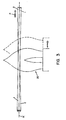
- FIGS. 1-7 show steps in forming a broadband fiber optic coupler according to a preferred embodiment of the present invention;
- FIGS. 8A-8E are enlarged cross-sectional views taken at several locations along the fiber optic structure shown in FIG. 2;
- FIGS. 9A-9E are enlarged cross-sectional views taken at several locations along the fiber optic structure shown in FIG. 6;
- FIGS. 10-11 show steps of forming a broadband fiber optic coupler according to an alternate embodiment of the present invention;
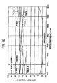
- FIG. 12 is a graphical illustration of the spectral response as a function of wavelength for light launched into the first input fiber of a fused broadband 2x4 fiber optic coupler constructed in accordance to the present invention; and
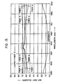
- FIG. 13 is a graphical illustration of a spectral response as a function of wavelength for light launched into the second input fiber of a fused broadband 2x4 fiber optic coupler constructed in accordance to the present invention.
-
- Referring now to the drawings wherein the showings are for the purpose of illustrating a preferred embodiment of the invention, and not for the purpose of limiting same, FIGS. 1-6 illustrate a method of fabricating a 2x4 broadband fiber optic coupler in accordance with the present invention.
- According to the present invention, four lengths of single mode optical fiber are stripped of all protective buffers and coatings so as to expose a region of bare glass for a length of approximately 2.54 cm (1 inch). The exposed regions of two of the four fibers, designated 1 and 2 in the drawings, are brought together side-by-side, as shown in FIGS. 1 and 2. In the drawings, all optical fibers are shown without protective buffers or coatings, and one end of the fibers is shown sectioned to illustrate generally the core and cladding of each optical fiber. According to the present invention,
fibers 1 and 2 are carefully wrapped over each other several times to join one to the other and thereby create a "wrapped fiber zone." As used hereinafter, the phrase "wrapped fiber zone" refers to the lengths of the exposed region offibers 1,2 which are wrapped relative to each other. FIG. 2 illustrates a portion of the wrapped fiber zone. In FIG. 2, fiber 1 is wrapped aroundfiber 2 and the respective fibers have moved 180° from their original positions relative to a line of contact designated "A," as best illustrated in FIGS. 8A-8C. FIG. 8E illustrates the position offibers 1, 2 wherefibers 1, 2 have been wrapped completely, i.e., have moved 360° from their initial positions. As used hereinafter, one "wrap" shall be defined as the change in position offibers 1, 2, as illustrated in FIGS. 8A-8E. - According to the embodiment heretofore described,
fibers 1 and 2 in the "wrapped fiber zone" include at least one "wrap" (i.e., one 360° spiral). It is important to note thatfibers 1 and 2 are carefully "wrapped" relative to one another (as contrasted with "twisting" the two fibers) so as to avoid introducing any internal torsional stress infibers 1, 2 which may adversely affect the polarization properties of light propagating therethrough. In other words, twisting of the individual fibers is to be avoided because of the detrimental effect such twisting has on the optical properties offibers 1, 2. In this respect, the desired "wrapping" offibers 1 and 2 should not be accomplished by clamping the ends thereof and twisting them about a central axis. - With
fibers 1 and 2 carefully wrapped relative to each other, the axial ends offibers 1, 2 are then pulled taut so as to bring the twofibers 1, 2 into contact with each other. As indicated above, FIGS. 8A-8E show the relative position offibers 1, 2 at various spaced apart locations along one "wrap." Whenfibers 1, 2 are pulled taut, a continuous line of contact is formed betweenfibers 1 and 2. Ideally,fibers 1, 2 would be arranged in such a manner so as to produce a line of contact along a straight linear axis. In reality, becausefibers 1 and 2 are wrapped about each other, the line of contact betweenfibers 1 and 2 is not along an exact, true "straight line" or "axis," but rather is along a line which is curvilinear, having a contour which may best be described as helical with an extremely gentle pitch. Accordingly, as used herein, the term "line" is intended to describe a line which may be straight or curvilinear. Accordingly, whenfibers 1, 2 are pulled taut, a line of contact is formed in the wrapped fiber zone. The line of contact, designated "A" in the drawing, is generally straight or curvilinear. - With
fibers 1 and 2 in contact with each other, heat is applied to the exposed regions of the glass. According to the present invention, a gas flame, designated 20 in FIG. 3, is used to provide the necessary heat. (As will be appreciated by those skilled in the art,flame 20 depicted in FIG. 3 is not drawn to scale.)Fibers 1, 2 may also be heated by laser energy, induction heating or any other heating means, without deviating from the present invention.Flame 20 is applied to the exposed region of glass offibers 1, 2 to soften same. As illustrated in FIG. 3,flame 20 is moved alongfibers 1, 2 along a portion of the wrappedfibers 1, 2. Whileflame 20 moves alongfibers 1, 2, they are slowly pulled axially from one direction.Fibers 1, 2 are axially pulled as schematically represented by arrow "P" in FIG. 3 in order to stretchfibers 1, 2 and reduce their diameters. The heated sections offibers 1, 2 have a constant yet reduced diameter over the length of the wrappedfibers 1, 2 scanned byflame 20. The final diameter offibers 1, 2 in the heated region is controlled by the length to whichfibers 1, 2 are stretched. It is important to note that a uniform relative motion betweenfibers 1, 2 andflame 20 is required to obtain constant fiber diameters along the heated sections offibers 1, 2. The method of reducing the fibers as heretofore described is discussed in U.S. Letters Patent No. 4,798,438, the disclosure of which is incorporated herein by reference. Axial force "P" exerted onfibers 1, 2, also ensures thatfibers 1, 2 remain in contact during the heating of the fibers. According to the present invention, the actual reduction in size offibers 1, 2 is relatively slight. Preferably, the length offibers 1, 2 are stretched such that the actual reduction in the diameter offibers 1, 2 is less than 10%, and more preferably about 5%. In this respect, for the purpose of illustration, the resulting diameters offibers 1, 2 as shown in FIGS. 3-7, are noticeably smaller than the original diameters offibers 1, 2 shown in FIG. 2 and smaller than the diameters offibers fibers 1, 2, the heating and pulling of the two contactingfibers 1, 2, fusesfibers 1, 2 together into a single twin-fiber structure along the heated length as a result of the softening of the glass. Also, it is important that the wrapping offibers 1, 2 produces continuous linear contact betweenfibers 1, 2 whenfibers 1, 2 are pulled taut. The resulting twin-fiber structure is therefore fused together along a line of contact. Wrapped and fusedfibers 1, 2 produce grooves or recesses 13, 14 formed on opposite sides of the fusedfibers 1, 2. These diametrically opposed grooves or recesses 13, 14 spiral along a generally helical path around the line of contact of the fusedfibers 1, 2. - A
third fiber 3 is wrapped about fusedfibers 1, 2, as schematically shown in FIGS. 4 and 9..Third fiber 3 is positioned to one side of fusedfibers 1, 2 withinhelical groove 13.Third fiber 3 is assembled with fusedfibers 1, 2 basically by winding it in the same direction of wrap as fusedfibers 1, 2.Third fiber 3 is then pulled taut at its axial ends to cause it to seat or nest itself intogroove 13, ensuring contact with bothfibers 1, 2. In this respect, becausefibers 1, 2 are fused together, there is no relative movement betweenfibers 1, 2 whenthird fiber 3 is wrapped around and pulled taut. As a result of the slight wrap ofthird fiber 3, the axial force pullingthird fiber 3 taut produces radial forces directed towardfibers 1, 2. These forces causethird fiber 3 to move into contact with fusedfibers 1, 2 thereby ensuring a positive seating or nesting ofthird fiber 3 ingroove 13, and thereby ensuring good contact betweenthird fiber 3 and fusedfibers 1, 2. - As schematically shown in FIG. 5, a
fourth fiber 4 is similarly positioned to the side of the fusedfibers 1, 2 withingroove 14 and is wrapped around the now three-fiber bundle. Again, it is important to ensure thatfourth fiber 4 is wrapped around fusedfibers 1, 2 in the same wrap direction as is initially introduced to fusedfibers 1, 2. Again, by pulling the end offourth fiber 4 in an axial direction, radial forces are exerted onfourth fiber 4 causing it to seat itself ingroove 14, thereby ensuring contact with both fibers. - With third and
fourth fibers source 20 preferably oscillates back and forth parallel to the fiber bundle. Fibers 1-4 are pulled simultaneously from both sides while light is launched into one of the original fusedfibers 1, 2. By conventionally known means, the light exiting each of the four output ports (fibers) is monitored using a photodetector (not shown). As fibers 1-4 are heated and pulled, light begins to couple from the input fiber to the other fibers in the bundle. The heating and elongation process is continued until the percentage of light in each of the output ports of the coupler is substantially equal at both 1310 nm and 1550 nm. Once this condition is met, the heating and stretching of fibers 1-4 is then terminated. The heating and elongation process thus produces a drawn fused tapered coupling region, as schematically shown in FIG. 7, which may then be attached to a silica substrate or other support surface (not shown). - The broadband performance of a 2x4 coupler fabricated in accordance with the present invention is illustrated in FIGS. 12 and 13. The test data were obtained by injecting white light into
launch fibers 1 and 2 and scanning the outputs offibers launch fibers 1 and 2, the uniformity of the four outputs was less than 2 dB. Hence, the 2x4 coupler exhibits uniform and broadband coupling over an extended range of wavelengths. The nearly identical behavior of the coupler when light is launched intofibers 1 and 2 clearly demonstrates the ability of the coupler to function as either a 1x4 or 2x4 splitter. The present invention also offers advantages over other methods resulting in an easier, more reliable and reproducible method of fabrication. - Referring now to FIGS. 10 and 11, an alternate embodiment of the present invention is shown. FIG. 10 shows two lengths of optical fiber, designated 101, 102.
Fibers flat surfaces 101a, 102a axially along one side offibers Fibers surfaces 101a, 102a in contact with each other. As will be appreciated,flat surfaces 101a, 102a, facilitate maintainingfibers fibers fibers fibers third fiber 103 may be positioned ingroove 113 and afourth fiber 104 may be positioned withingroove 114. The four fiber bundle is pulled taut in a manner as described above. Simultaneously, the four fiber bundle is heated and pulled while light is launched into one of the original twofibers - Whereas the embodiment previously discussed utilized the inward axial force caused by the wrapping of the fibers to maintain contact between the initial two
fibers 1, 2, the later described embodiment utilizesflat surfaces 101a, 102a to facilitate mating and contact betweeninitial fibers - The present invention thus provides a method for producing couplers having a more uniform spectral response over a wide band of wavelengths. It is believed that the accurate positioning and alignment of the fibers in positive contact with each other facilitates the improved operating characteristic of couplers according to the present invention. As seen in FIGS. 8 and 9, each fiber in the coupler is in intimate contact with the launch fiber prior to elongation and coupling. It is believed that this positioning and the relative initial spacing between the cores, which spacing is fairly similar because of the similarly sized fiber and minimum reduction during the fusing step, contribute to the exceptional performance of couplers formed according to the present invention. It is also believed that improved operating characteristics results from the use of only two different fiber diameters, as contrasted with three or more different diameters. By using two pairs of similar sized fibers, the positions and positioning of the fibers relative to each other are more accurately controlled, and facilitate the accurate alignment discussed above.
- Importantly, the present invention provides a coupler which may be used as a 2x4 component, but which can also function automatically as a 1x4 component by simply utilizing one of
fibers 1,2 as the launch fiber. In this respect, while the invention has been described with respect to a 2x4 coupler, it will be appreciated that coupled fibers including three (3) or four fibers may also be produced without deviating from the present invention. Other modifications and alterations will occur to those skilled in the art upon a reading and understanding of the present invention.
Claims (4)
- A method of forming a broadband fiber optic coupler comprising four optical fibers, characterised by the steps of:a) initially arranging a first optical fiber (1) and a second optical fiber (2) of substantially the same diameters side-by-side;b) then bringing said first and second optical fibers together into intimate contact with each other;c) subsequently simultaneously heating and tensioning said fibers together until said first and second optical fibers fuse together, said two fibers forming grooves (13,14) along opposite sides of said the line of fusion;d) then positioning a third optical fiber (3) in intimate contact with said first and second optical fibers within one of the grooves (13) formed by said first and second optical fibers, and positioning a fourth optical fiber (4) in intimate contact with said first and second optical fibers within the other groove (14) formed by said optical fibers; ande) finally heating, elongating and fusing said optical fibers together to achieve a broadband coupler.
- A method as claimed in claim 1, wherein said third and fourth optical fibers (3,4) have the same diameter.
- A method as claimed in claim 1 or 2, wherein said first and second optical fibers (1,2) are brought into contact with each other by wrapping said fiber around each other.
- A method as claimed in any preceding claim, wherein said first and second fibers (101,102) are brought into contact with each other along a flat surface (101a,102a) formed into each fiber.
Applications Claiming Priority (2)
| Application Number | Priority Date | Filing Date | Title |
|---|---|---|---|
| US577344 | 1990-09-04 | ||
| US08/577,344 US5644666A (en) | 1995-12-22 | 1995-12-22 | Broadband optical fiber coupler and method of making |
Publications (3)
| Publication Number | Publication Date |
|---|---|
| EP0780709A2 EP0780709A2 (en) | 1997-06-25 |
| EP0780709A3 EP0780709A3 (en) | 1997-11-05 |
| EP0780709B1 true EP0780709B1 (en) | 2003-04-23 |
Family
ID=24308308
Family Applications (1)
| Application Number | Title | Priority Date | Filing Date |
|---|---|---|---|
| EP96309193A Expired - Lifetime EP0780709B1 (en) | 1995-12-22 | 1996-12-17 | Broadband coupler |
Country Status (4)
| Country | Link |
|---|---|
| US (1) | US5644666A (en) |
| EP (1) | EP0780709B1 (en) |
| CA (1) | CA2190044C (en) |
| DE (1) | DE69627618D1 (en) |
Families Citing this family (9)
| Publication number | Priority date | Publication date | Assignee | Title |
|---|---|---|---|---|
| CA2123757C (en) * | 1994-05-17 | 2002-06-25 | Francois Gonthier | Method for making optical waveguide couplers with low wavelength sensitivity and couplers thereby produced |
| US6078716A (en) | 1999-03-23 | 2000-06-20 | E-Tek Dynamics, Inc. | Thermally expanded multiple core fiber |
| US6246518B1 (en) | 1999-03-25 | 2001-06-12 | E-Tek Dynamics, Inc. | Reflection type optical isolator |
| US6374009B1 (en) | 1999-05-10 | 2002-04-16 | Jds Uniphase Corporation | TEMC fiber based optical switch |
| US6525864B1 (en) | 2000-07-20 | 2003-02-25 | Nayna Networks, Inc. | Integrated mirror array and circuit device |
| US6771851B1 (en) | 2001-06-19 | 2004-08-03 | Nayna Networks | Fast switching method for a micro-mirror device for optical switching applications |
| US6636670B2 (en) * | 2001-09-20 | 2003-10-21 | Gould Optronics, Inc. | Device for generating electrical signal that is a function of the optical power in optical fiber, and method of forming the same |
| US7961764B2 (en) * | 2007-09-12 | 2011-06-14 | Howard Hughes Medical Institute | Nonlinear imaging using passive pulse splitters and related technologies |
| US9366821B2 (en) | 2012-03-02 | 2016-06-14 | Tyco Electronics Corporation | Method of forming fused coupler |
Citations (3)
| Publication number | Priority date | Publication date | Assignee | Title |
|---|---|---|---|---|
| US4154592A (en) * | 1978-02-21 | 1979-05-15 | Corning Glass Works | Method of drawing optical filaments |
| JPS5918921A (en) * | 1982-07-23 | 1984-01-31 | Nippon Telegr & Teleph Corp <Ntt> | Fiber type coupler and its manufacture |
| US5146527A (en) * | 1988-09-01 | 1992-09-08 | British Telecommunications Public Limited Company | Optical fibre splice |
Family Cites Families (16)
| Publication number | Priority date | Publication date | Assignee | Title |
|---|---|---|---|---|
| JPS55147604A (en) * | 1979-05-08 | 1980-11-17 | Toshiba Corp | Production of photo distributor |
| JPS5848014A (en) * | 1981-09-16 | 1983-03-19 | Showa Electric Wire & Cable Co Ltd | Manufacture of optical distributor |
| JPS58156917A (en) * | 1982-03-12 | 1983-09-19 | Nippon Telegr & Teleph Corp <Ntt> | Directional coupler for single mode optical fiber |
| EP0219096A3 (en) * | 1985-10-16 | 1989-08-16 | Hitachi, Ltd. | Optical fiber star coupler and method of manufacturing the same |
| US4798438A (en) * | 1986-10-15 | 1989-01-17 | Gould Inc. | Method of making a single-mode evanescent-wave coupler having reduced wavelength dependence |
| GB9015775D0 (en) * | 1990-07-18 | 1990-09-05 | British Telecomm | Optical fibre coupler |
| US5195151A (en) * | 1990-12-17 | 1993-03-16 | Aster Corporation | Optical fiber couplers and methods of their manufacture |
| GB2253071A (en) * | 1991-02-20 | 1992-08-26 | Telecommunication Lab Director | Fibre star amplifier coupler |
| AU643115B2 (en) * | 1991-06-03 | 1993-11-04 | Sumiden Opcom Ltd. | Method for farbicating optical fibre couplers |
| US5283847A (en) * | 1991-09-09 | 1994-02-01 | Sumitomo Electric Industries, Ltd. | Method of manufacturing and evaluating an optical fiber coupler and apparatus therefor |
| JP3092301B2 (en) * | 1992-03-04 | 2000-09-25 | 住友電気工業株式会社 | Optical fiber coupler and manufacturing method thereof |
| US5355426A (en) * | 1992-09-02 | 1994-10-11 | Gould Electronics Inc. | Broadband MXN optical fiber couplers and method of making |
| US5295210A (en) * | 1992-12-31 | 1994-03-15 | Corning Incorporated | Optical waveguide fiber achromatic coupler |
| US5408554A (en) * | 1993-12-17 | 1995-04-18 | Porta System Corporation | Fiber optic coupling |
| DE69430756T2 (en) * | 1993-11-10 | 2002-10-24 | Adc Australia Pty. Ltd., Symonston | FIBER OPTICAL COUPLER |
| US5408556A (en) * | 1993-12-06 | 1995-04-18 | Kaptron, Inc. | 1 X N splitter for single-mode fibers and method of construction |
-
1995
- 1995-12-22 US US08/577,344 patent/US5644666A/en not_active Expired - Fee Related
-
1996
- 1996-11-12 CA CA002190044A patent/CA2190044C/en not_active Expired - Fee Related
- 1996-12-17 DE DE69627618T patent/DE69627618D1/en not_active Expired - Lifetime
- 1996-12-17 EP EP96309193A patent/EP0780709B1/en not_active Expired - Lifetime
Patent Citations (3)
| Publication number | Priority date | Publication date | Assignee | Title |
|---|---|---|---|---|
| US4154592A (en) * | 1978-02-21 | 1979-05-15 | Corning Glass Works | Method of drawing optical filaments |
| JPS5918921A (en) * | 1982-07-23 | 1984-01-31 | Nippon Telegr & Teleph Corp <Ntt> | Fiber type coupler and its manufacture |
| US5146527A (en) * | 1988-09-01 | 1992-09-08 | British Telecommunications Public Limited Company | Optical fibre splice |
Also Published As
| Publication number | Publication date |
|---|---|
| CA2190044C (en) | 2001-10-16 |
| EP0780709A3 (en) | 1997-11-05 |
| DE69627618D1 (en) | 2003-05-28 |
| CA2190044A1 (en) | 1997-06-23 |
| US5644666A (en) | 1997-07-01 |
| EP0780709A2 (en) | 1997-06-25 |
Similar Documents
| Publication | Publication Date | Title |
|---|---|---|
| US5355426A (en) | Broadband MXN optical fiber couplers and method of making | |
| US4330170A (en) | Low-loss star couplers for optical fiber systems | |
| EP1440338B1 (en) | Splice joint and process for joining a microstructured optical fiber and a conventional optical fiber | |
| JP2645458B2 (en) | Method of manufacturing single mode evanescent wave optical coupler | |
| EP0628839B1 (en) | Low loss coupler | |
| EP0840148B1 (en) | Optical fibre coupler and a fabrication method for the same | |
| JPH0667055A (en) | Fiberoptic coupler and manufacture thereof | |
| EP0635140B1 (en) | One by eight optical fiber coupler | |
| AU700855B2 (en) | Low loss fiber optic coupler and method | |
| US5644666A (en) | Broadband optical fiber coupler and method of making | |
| US5943458A (en) | Mach-Zehnder interferometric devices with composite fibers | |
| US5035480A (en) | Star-couplers with biconical mixing elements and methods for making the same | |
| US6731842B2 (en) | Microbend fused fiber coupler method and apparatus | |
| US6301412B1 (en) | Apparatus and method for making multi-branching optical coupler | |
| US5373572A (en) | Method of forming multiport optical fibre coupler and the coupler so formed | |
| AU714724B2 (en) | Mach-zehnder interferometric devices with composite fibers | |
| JP3101958B2 (en) | Broadband coupler and method of manufacturing the same | |
| JP2879266B2 (en) | Broadband optical fiber coupler | |
| JPH04138404A (en) | Optical fiber coupler and arraying member for optical fiber coupler | |
| JP2958179B2 (en) | Optical fiber coupler and manufacturing method thereof | |
| JP2000206361A (en) | Optical fiber type multi-branch coupler and manufacturing method thereof | |
| EP1091222A2 (en) | Method of making Mach-Zehnder interferometric device with composite fibers | |
| JPH04296705A (en) | Optical fiber coupler | |
| JP2000193845A (en) | Branch optical coupler for branching input light into a plurality of fibers and method of manufacturing the same | |
| JPH11167041A (en) | Multi-branch optical coupler |
Legal Events
| Date | Code | Title | Description |
|---|---|---|---|
| PUAI | Public reference made under article 153(3) epc to a published international application that has entered the european phase |
Free format text: ORIGINAL CODE: 0009012 |
|
| AK | Designated contracting states |
Kind code of ref document: A2 Designated state(s): CH DE DK ES FR GB IE IT LI SE |
|
| PUAL | Search report despatched |
Free format text: ORIGINAL CODE: 0009013 |
|
| AK | Designated contracting states |
Kind code of ref document: A3 Designated state(s): CH DE DK ES FR GB IE IT LI SE |
|
| 17P | Request for examination filed |
Effective date: 19971219 |
|
| RAP1 | Party data changed (applicant data changed or rights of an application transferred) |
Owner name: GA-TEK, INC. (DOING BUSINESS AS GOULD ELECTRONICS |
|
| RAP1 | Party data changed (applicant data changed or rights of an application transferred) |
Owner name: GOULD OPTRONICS INC. |
|
| 17Q | First examination report despatched |
Effective date: 20010531 |
|
| GRAG | Despatch of communication of intention to grant |
Free format text: ORIGINAL CODE: EPIDOS AGRA |
|
| GRAG | Despatch of communication of intention to grant |
Free format text: ORIGINAL CODE: EPIDOS AGRA |
|
| GRAH | Despatch of communication of intention to grant a patent |
Free format text: ORIGINAL CODE: EPIDOS IGRA |
|
| GRAH | Despatch of communication of intention to grant a patent |
Free format text: ORIGINAL CODE: EPIDOS IGRA |
|
| GRAA | (expected) grant |
Free format text: ORIGINAL CODE: 0009210 |
|
| AK | Designated contracting states |
Designated state(s): CH DE DK ES FR GB IE IT LI SE |
|
| PG25 | Lapsed in a contracting state [announced via postgrant information from national office to epo] |
Ref country code: LI Free format text: LAPSE BECAUSE OF FAILURE TO SUBMIT A TRANSLATION OF THE DESCRIPTION OR TO PAY THE FEE WITHIN THE PRESCRIBED TIME-LIMIT Effective date: 20030423 Ref country code: IT Free format text: LAPSE BECAUSE OF FAILURE TO SUBMIT A TRANSLATION OF THE DESCRIPTION OR TO PAY THE FEE WITHIN THE PRESCRIBED TIME-LIMIT;WARNING: LAPSES OF ITALIAN PATENTS WITH EFFECTIVE DATE BEFORE 2007 MAY HAVE OCCURRED AT ANY TIME BEFORE 2007. THE CORRECT EFFECTIVE DATE MAY BE DIFFERENT FROM THE ONE RECORDED. Effective date: 20030423 Ref country code: FR Free format text: LAPSE BECAUSE OF NON-PAYMENT OF DUE FEES Effective date: 20030423 Ref country code: CH Free format text: LAPSE BECAUSE OF FAILURE TO SUBMIT A TRANSLATION OF THE DESCRIPTION OR TO PAY THE FEE WITHIN THE PRESCRIBED TIME-LIMIT Effective date: 20030423 |
|
| REG | Reference to a national code |
Ref country code: GB Ref legal event code: FG4D |
|
| REG | Reference to a national code |
Ref country code: CH Ref legal event code: EP |
|
| REF | Corresponds to: |
Ref document number: 69627618 Country of ref document: DE Date of ref document: 20030528 Kind code of ref document: P |
|
| REG | Reference to a national code |
Ref country code: IE Ref legal event code: FG4D |
|
| PG25 | Lapsed in a contracting state [announced via postgrant information from national office to epo] |
Ref country code: SE Free format text: LAPSE BECAUSE OF FAILURE TO SUBMIT A TRANSLATION OF THE DESCRIPTION OR TO PAY THE FEE WITHIN THE PRESCRIBED TIME-LIMIT Effective date: 20030723 Ref country code: DK Free format text: LAPSE BECAUSE OF FAILURE TO SUBMIT A TRANSLATION OF THE DESCRIPTION OR TO PAY THE FEE WITHIN THE PRESCRIBED TIME-LIMIT Effective date: 20030723 |
|
| PG25 | Lapsed in a contracting state [announced via postgrant information from national office to epo] |
Ref country code: DE Free format text: LAPSE BECAUSE OF FAILURE TO SUBMIT A TRANSLATION OF THE DESCRIPTION OR TO PAY THE FEE WITHIN THE PRESCRIBED TIME-LIMIT Effective date: 20030724 |
|
| PG25 | Lapsed in a contracting state [announced via postgrant information from national office to epo] |
Ref country code: ES Free format text: LAPSE BECAUSE OF FAILURE TO SUBMIT A TRANSLATION OF THE DESCRIPTION OR TO PAY THE FEE WITHIN THE PRESCRIBED TIME-LIMIT Effective date: 20031030 |
|
| REG | Reference to a national code |
Ref country code: CH Ref legal event code: PL |
|
| PG25 | Lapsed in a contracting state [announced via postgrant information from national office to epo] |
Ref country code: IE Free format text: LAPSE BECAUSE OF NON-PAYMENT OF DUE FEES Effective date: 20031217 |
|
| PGFP | Annual fee paid to national office [announced via postgrant information from national office to epo] |
Ref country code: GB Payment date: 20031217 Year of fee payment: 8 |
|
| PLBE | No opposition filed within time limit |
Free format text: ORIGINAL CODE: 0009261 |
|
| STAA | Information on the status of an ep patent application or granted ep patent |
Free format text: STATUS: NO OPPOSITION FILED WITHIN TIME LIMIT |
|
| 26N | No opposition filed |
Effective date: 20040126 |
|
| EN | Fr: translation not filed | ||
| REG | Reference to a national code |
Ref country code: IE Ref legal event code: MM4A |
|
| PG25 | Lapsed in a contracting state [announced via postgrant information from national office to epo] |
Ref country code: GB Free format text: LAPSE BECAUSE OF NON-PAYMENT OF DUE FEES Effective date: 20041217 |
|
| GBPC | Gb: european patent ceased through non-payment of renewal fee |
Effective date: 20041217 |