US5195151A - Optical fiber couplers and methods of their manufacture - Google Patents
Optical fiber couplers and methods of their manufacture Download PDFInfo
- Publication number
- US5195151A US5195151A US07/628,597 US62859790A US5195151A US 5195151 A US5195151 A US 5195151A US 62859790 A US62859790 A US 62859790A US 5195151 A US5195151 A US 5195151A
- Authority
- US
- United States
- Prior art keywords
- fibers
- coupling
- region
- fiber
- coupler
- Prior art date
- Legal status (The legal status is an assumption and is not a legal conclusion. Google has not performed a legal analysis and makes no representation as to the accuracy of the status listed.)
- Expired - Fee Related
Links
- 238000000034 method Methods 0.000 title claims abstract description 37
- 239000013307 optical fiber Substances 0.000 title claims abstract description 22
- 238000004519 manufacturing process Methods 0.000 title claims abstract description 21
- 239000000835 fiber Substances 0.000 claims abstract description 333
- 230000008878 coupling Effects 0.000 claims abstract description 199
- 238000010168 coupling process Methods 0.000 claims abstract description 199
- 238000005859 coupling reaction Methods 0.000 claims abstract description 199
- 230000003287 optical effect Effects 0.000 claims description 55
- 230000005284 excitation Effects 0.000 claims description 8
- 230000000737 periodic effect Effects 0.000 claims description 7
- 230000010287 polarization Effects 0.000 claims description 7
- 239000000758 substrate Substances 0.000 claims description 7
- 230000001747 exhibiting effect Effects 0.000 claims description 6
- 238000005452 bending Methods 0.000 claims description 3
- 239000000470 constituent Substances 0.000 claims description 3
- 238000004806 packaging method and process Methods 0.000 claims description 3
- 230000004044 response Effects 0.000 abstract description 14
- 238000010276 construction Methods 0.000 abstract description 2
- 230000004927 fusion Effects 0.000 description 16
- 230000008901 benefit Effects 0.000 description 11
- 238000005530 etching Methods 0.000 description 7
- 230000007423 decrease Effects 0.000 description 6
- 238000013461 design Methods 0.000 description 6
- 230000007613 environmental effect Effects 0.000 description 6
- 230000008569 process Effects 0.000 description 4
- 239000000853 adhesive Substances 0.000 description 3
- 230000001070 adhesive effect Effects 0.000 description 3
- 238000013459 approach Methods 0.000 description 3
- 230000001186 cumulative effect Effects 0.000 description 3
- 230000001419 dependent effect Effects 0.000 description 3
- 238000009826 distribution Methods 0.000 description 3
- 238000002474 experimental method Methods 0.000 description 3
- 230000002349 favourable effect Effects 0.000 description 3
- 238000005253 cladding Methods 0.000 description 2
- 238000004891 communication Methods 0.000 description 2
- 230000003247 decreasing effect Effects 0.000 description 2
- 230000000994 depressogenic effect Effects 0.000 description 2
- 230000000694 effects Effects 0.000 description 2
- 230000006872 improvement Effects 0.000 description 2
- 230000010355 oscillation Effects 0.000 description 2
- 230000003534 oscillatory effect Effects 0.000 description 2
- 230000001681 protective effect Effects 0.000 description 2
- 239000004593 Epoxy Substances 0.000 description 1
- 230000009471 action Effects 0.000 description 1
- 230000001154 acute effect Effects 0.000 description 1
- 230000015556 catabolic process Effects 0.000 description 1
- 238000006731 degradation reaction Methods 0.000 description 1
- -1 e.g. Substances 0.000 description 1
- 239000011521 glass Substances 0.000 description 1
- 230000001902 propagating effect Effects 0.000 description 1
- 238000003908 quality control method Methods 0.000 description 1
- 230000009467 reduction Effects 0.000 description 1
- 230000035945 sensitivity Effects 0.000 description 1
- 230000035939 shock Effects 0.000 description 1
- 238000012956 testing procedure Methods 0.000 description 1
- 238000012546 transfer Methods 0.000 description 1
- 238000013519 translation Methods 0.000 description 1
Images


Classifications
-
- G—PHYSICS
- G02—OPTICS
- G02B—OPTICAL ELEMENTS, SYSTEMS OR APPARATUS
- G02B6/00—Light guides; Structural details of arrangements comprising light guides and other optical elements, e.g. couplings
- G02B6/24—Coupling light guides
- G02B6/26—Optical coupling means
- G02B6/28—Optical coupling means having data bus means, i.e. plural waveguides interconnected and providing an inherently bidirectional system by mixing and splitting signals
- G02B6/2804—Optical coupling means having data bus means, i.e. plural waveguides interconnected and providing an inherently bidirectional system by mixing and splitting signals forming multipart couplers without wavelength selective elements, e.g. "T" couplers, star couplers
- G02B6/2821—Optical coupling means having data bus means, i.e. plural waveguides interconnected and providing an inherently bidirectional system by mixing and splitting signals forming multipart couplers without wavelength selective elements, e.g. "T" couplers, star couplers using lateral coupling between contiguous fibres to split or combine optical signals
- G02B6/2835—Optical coupling means having data bus means, i.e. plural waveguides interconnected and providing an inherently bidirectional system by mixing and splitting signals forming multipart couplers without wavelength selective elements, e.g. "T" couplers, star couplers using lateral coupling between contiguous fibres to split or combine optical signals formed or shaped by thermal treatment, e.g. couplers
-
- G—PHYSICS
- G02—OPTICS
- G02B—OPTICAL ELEMENTS, SYSTEMS OR APPARATUS
- G02B6/00—Light guides; Structural details of arrangements comprising light guides and other optical elements, e.g. couplings
- G02B6/24—Coupling light guides
- G02B6/26—Optical coupling means
- G02B6/28—Optical coupling means having data bus means, i.e. plural waveguides interconnected and providing an inherently bidirectional system by mixing and splitting signals
- G02B6/2804—Optical coupling means having data bus means, i.e. plural waveguides interconnected and providing an inherently bidirectional system by mixing and splitting signals forming multipart couplers without wavelength selective elements, e.g. "T" couplers, star couplers
- G02B6/2821—Optical coupling means having data bus means, i.e. plural waveguides interconnected and providing an inherently bidirectional system by mixing and splitting signals forming multipart couplers without wavelength selective elements, e.g. "T" couplers, star couplers using lateral coupling between contiguous fibres to split or combine optical signals
-
- G—PHYSICS
- G02—OPTICS
- G02B—OPTICAL ELEMENTS, SYSTEMS OR APPARATUS
- G02B6/00—Light guides; Structural details of arrangements comprising light guides and other optical elements, e.g. couplings
- G02B6/24—Coupling light guides
- G02B6/26—Optical coupling means
- G02B6/28—Optical coupling means having data bus means, i.e. plural waveguides interconnected and providing an inherently bidirectional system by mixing and splitting signals
- G02B6/2804—Optical coupling means having data bus means, i.e. plural waveguides interconnected and providing an inherently bidirectional system by mixing and splitting signals forming multipart couplers without wavelength selective elements, e.g. "T" couplers, star couplers
- G02B6/2856—Optical coupling means having data bus means, i.e. plural waveguides interconnected and providing an inherently bidirectional system by mixing and splitting signals forming multipart couplers without wavelength selective elements, e.g. "T" couplers, star couplers formed or shaped by thermal heating means, e.g. splitting, branching and/or combining elements
Definitions
- the invention relates to achieving practical fiber optic couplers for single mode fibers that have improved constancy of coupler performance.
- Fiber optic systems feature fiberoptic splitters or couplers as a means to branch optical power into more than one fiber waveguide. Often it is desired to couple optical power from a common bus fiber into many side branches. Taps are located serially along the length of the bus fiber, each tap providing only a small fraction of the total power carried on the bus for use by attached equipment
- the optical power budget of such a system typically interrelates with the amount of loss of optical power that can be tolerated at each tap point. Since the power available at each tap point depends upon the total power remaining in the bus fiber at that point, system designs critically depend on the splitting ratio of each coupler being sufficiently constant over the entire optical wavelength band of sources usable in the system. Additionally, the coupling ratio must be sufficiently constant in coupling ratio with respect to changes in temperature, physical stress and input optical polarization.
- Couplers having a nominally constant coupling ratio over the wavelength band of interest are referred to as wideband couplers, wavelength flattened couplers, wavelength independent couplers, broad-band couplers, etc.
- couplers that have a sufficient constancy over a sufficient band width, with acceptable excess loss, and sufficient constancy in performance with changes in the temperature and stress environment, systems can be provided for working over a design range of wavelengths and environmental conditions. It follows that improvement in the constancy of coupling ratio while keeping excess loss within acceptable limits can lead to important improvement in the performance and lower cost for many optical systems.
- wideband couplers have been made by preselection of the difference in propagation constant of the constituent fibers relative to the desired coupling ratio.
- the first maximum a relatively flat portion of the coupling ratio curve that oscillates during drawing of the coupler, can be made to coincide with the coupling ratio desired.
- the coupling performance of the resulting coupler can be relatively constant due to operating with the flat portion of the coupling ratio curve that occurs at maxima.
- Fibers having such preselected, different propagation constants e.g., can be fused together in a manner to achieve identical coupling at two wavelengths by selection of the stopping point during fusing/drawing of the fibers, either by observing the varying coupling ratios or selecting manufacturing parameters that have been predetermined to produce the desired ratio.
- This method is most useful in a two wavelength system where both wavelengths are well known in advance.
- One of the fibers of different propagation constants can e.g. be powered by the two wavelengths while the fibers are fused by thermal drawing. Drawing is stopped as soon as the desired coupling ratio at wavelengths is observed.
- the coupling ratio in such cases is the result of the amount and nature (constructive) of the interference between the symmetric and antisymmetric modes in each of which substantial energy is propagating in the coupler.
- couplers made from fibers of different propagation constant drawn to an early occurrence of the desired coupling ratio as "short-draw Delta-B" type wideband couplers.
- a difference in propagation constant of two fibers is acquired in many ways.
- identical fibers are processed to have different diameters, e.g., by drawing one fiber into a tapered section of reduced diameter relative to the other fiber.
- the tapered section is then fused with an unprocessed fiber or with a fiber that was tapered more or less than the first fiber.
- Different propagation constants can also be obtained by etching one or both fibers so that their diameters are different before fusion or by selecting fibers with different V numbers.
- Couplers made in this manner typically demonstrate fairly low excess losses but often exhibit coupling ratio variations of +/-9% or more over about a 300 nanometer optical wavelength range. This degree of coupling variation can account for significant cumulative errors in system power budget when many such couplers are used as serial taps.
- wavelength response flattening has also been achieved by fusing fibers that have different core refractive indices.
- the desired coupling ratio is dependent upon the degree of interference between the symmetric and antisymmetric modes in which the energy of the coupler propagates.
- the utility of such a coupler may in some cases be limited by the presence of dissimilar glasses.
- splicing of fibers with differing indices into a system bus fiber creates cumulative splicing loss variations that may prove intolerable to system designers.
- quality control of two different fibers may be more costly than control of a single type of fiber.
- optical power loss of about 50% was observed by the authors. Even if such excess loss might be tolerable in a few applications, the majority of communications systems designs cannot of course tolerate the repeated loss of half the system optical power at each splitting point.
- Couplers which perform this branching are often referred to as star couplers.
- Star couplers can be made by fusing more than two fibers in a common fused region.
- a star coupler of this type intrinsically has an equal number of input and output fibers. In a single optical wavelength system application, typically only one of the fibers is used as the input. If more than one wavelength is used in the system, each separate wavelength may be input on a different optical fiber. The action of the coupler is to split the sum of optical power in each input fiber into more or less equal fractions of the input sum in each output fiber.
- star couplers are designated as N ⁇ N or 1 ⁇ N couplers, N denoting the number of fused fibers.
- a preferred method of prior teachings disposes six fibers around a central fiber. All seven of these fibers have substantially identical diameters. So doing provides optimum coupling uniformity. Such a coupler is drawn until the coupling ratios, as measured by the amounts of optical power carried in each output fiber, is essentially equal among all the fibers.
- This method can yield good coupling uniformity, low excess loss, and a degree of wideband behavior based on the principles noted above with regard to short draw couplers.
- the method is however limited to the fabrication of 1 ⁇ 6 and 1 ⁇ 7 port couplers. Most systems designs require 1 ⁇ 4 and 1 ⁇ 8 port configurations.
- Another method of performing branching into many fibers requires the fabrication of a tree structure using a collection of 2 ⁇ 2 couplers.
- the two outputs of a first 2 ⁇ 2 coupler are spliced to the input fibers of two more 2 ⁇ 2 couplers.
- the four outputs of these two couplers are spliced to the inputs of four more 2 ⁇ 2 couplers.
- a tree of seven 2 ⁇ 2 couplers provides two inputs and eight outputs.
- the fabrication of tree structures is, in principle simple, but coupling ratio variations among the couplers and splicing losses between couplers accumulate to cause wide variations in the fraction of input light present in each output. Couplers chosen for tree fabrication must be exceptionally accurate and stable, and the splicing procedure must be quite precise and repeatable.
- the "uniformity" of the coupling ratio describes the degree to which each of the N outputs carries essentially 1/N of the total output power; 2) the constancy of the coupling ratio with respect to wavelength; and, 3) the excess loss.
- Prior art has emphasized the importance of uniformity. In applications requiring equal splits of optical power, e.g., a bus which is split into eight equally tapped branches, uniformity is a critical parameter.
- the present invention addresses the various needs described above and provides improved, practical fiber optic couplers, splitters and similar devices.
- Fiber optic couplers formed of at least two single mode optical fibers, at least one of which is an input fiber, the fibers constructed and arranged in the manner that coupling between the input fiber and the other fibers limits antisymmetric modal energy to substantially less than 50% of the input energy, the coupling region of the coupler being fused and drawn to an extended length sufficient to cause cutoff of the antisymmetric mode energy, whereby the coupler exhibits coupling ratio stability over an extended range of wavelengths and an excess loss of substantially less than 50% are disclosed.
- the invention provides a fiber optic coupler comprised of fibers of differing propagation constants selected to limit the degree of excitation of the antisymmetric mode substantially below 50%, the fibers being fused together and drawn over a length exceeding the antisymmetric cut off, whereby substantially constant coupling performance is obtainable with excess loss substantially less than 50%.
- a wideband optical fiber coupler for single mode fibers comprises a thermally fused lateral intersection of two or more optical fibers wherein in one aspect, two fibers of differing diameters are placed in lateral contact and are then heated and elongated forming a long, fused, tapered coupling region.
- more than two fibers of the same or different diameters are arranged in lateral contact without particular regard to radial or azimuthal symmetry and are fused and elongated forming a long, fused, tapered coupling region.
- the coupler geometry again results in low energization of antisymmetric mode energy and resultant relatively low excess loss when drawn beyond antisymmetric mode cutoff.
- the coupling region length is made much greater than a coupling length by drawing the fibers typically nine millimeters or more, the actual draw distance depending upon initial fiber diameters.
- the coupling ratio stabilizes at a substantially predetermined value which depends, in the first aspect, on the ratio of the diameter of the fibers before drawing, and in the second aspect, upon the number of fibers coupled.
- the final coupling ratio lies in the range of 1 to 30 percent and is almost independent of input optical wavelength over a range of at least 400 nanometers.
- the coupling ratio varies by no more than+/-1% over this wavelength range.
- this exceptional wavelength insensitivity is accompanied by excess loss as low as 0.7 dB.
- couplers of prior art which can provide either coupling ratio flatness of+/-9% and fairly low excess loss, or coupling ratio flatness of+/-2% and excess loss of 50%
- the invention advantageously provides coupling ratio flatness of less than+/-1% and simultaneously improves the excess loss to less than 15%.(0.7 dB).
- couplers of the invention can be made to have any coupling ratio between 0 and 30% while still exhibiting low loss and wavelength insensitivity.
- 2 ⁇ 2 couplers of the first aspect and N ⁇ N couplers of the second aspect demonstrate stability of coupling ratio with respect to input optical polarization, environmental temperature, and mechanical stress.
- couplers of the first aspect of the invention are made using fibers of different diameters which are drawn until the coupling ratio stabilizes at a predetermined final value.
- the diameter difference is believed to minimize the amount of optical power coupled in the first higher order antisymmetric waveguide mode.
- drawing fibers of different diameter until the higher order antisymmetric mode is extinguished results in lower excess loss than drawing fibers of identical diameter.
- a method of making an extended bandwidth single-mode optical fiber coupler of the first aspect of the invention comprises arranging two fibers of differing diameters so that they contact each other along some lateral extent within a relatively short region within the continuous extent of the original fiber. Both of the fibers are then heated in the region of lateral contact and elongated by drawing, forming a fused tapered coupling region.
- one fiber, the throughput fiber is typically attached to an optical source. The outputs of both the throughput fiber and the coupled fiber are monitored during the drawing process. As the fibers are drawn, coupling begins to occur and can be observed by a steady growth of optical power in the coupled fiber. Light is coupled from the throughput fiber to the coupled fiber increasingly until a peak amount of the input optical power is transferred to the coupled fiber.
- the peak amount coupled is less than 100%. This peak transfer usually occurs within 3 to 5 millimeters of drawing, that distance depending on the initial diameters and other parameters of the fibers. After this first peak in coupling is reached, light begins to couple back into the throughput fiber. Soon, most of the light is carried by the throughput fiber once again. This oscillatory behavior continues with the distance between each peak of coupling, the so-called coupling length, decreasing as the draw length increases. Eventually, as drawing is continued through many coupling lengths, the oscillatory behavior ceases and the coupling ratio stabilizes at a predetermined value.
- Fibers having different diameters exhibit the characteristic that the final coupling ratio depends upon the diameters of the fibers before drawing. Fibers of equal diameter inherently have final coupling ratios of about 50 percent. Couplers of the invention can have predetermined values of coupling ratio in the range of 1 to 30 percent depending upon the ratio of starting diameters.
- the coupling ratio exhibits exceptional insensitivity to input optical wavelength over a range of at least 400 nanometers. Additionally, couplers of the invention have proven to exhibit coupling ratio variations of less than 1% due to complete input polarization rotation and temperature coefficients of coupling of 0.0016% per degree centigrade.
- Fibers manufactured originally to have different diameters can be used.
- a pair of originally identical fibers can be processed to have different diameters in a short region within the continuous extent of the coupler fiber leads.
- at least one original fiber might be processed by etching resulting in reducing the diameter of that fiber relative to the other fiber.
- fibers of different diameters are made from original fibers at least one of which is heated and drawn resulting in reducing the diameter of that on fiber relative to the other.
- a combination of etching and drawing techniques is also used.
- Depressed cladding fibers are best prepared by the combined etching and predrawing method just suggested.
- This method comprises first reducing the diameter of two fibers substantially equal amounts in regions of short length within the continuous extent of both of the fibers by etching. Subsequently, within an etched region of one of the fibers, the diameter is further reduced a predetermined amount. This may be accomplished by etching one fiber more than the other or by drawing one of etched regions to reduce its diameter.
- the predetermined amount is some fraction of the diameter of the reduced region of the first fiber. This fraction is typically derived empirically and is used to predetermine the final coupling ratio.
- the two fibers of differing diameters are then arranged to contact each other along some lateral extent of the reduced diameter regions, e.g., by wrapping the smaller diameter fiber around the larger diameter fiber.
- This provides the mechanical contact necessary to ensure proper fusion.
- the methods of the invention have proven that twisting causes no degradation in coupler performance when the drawing process is continued into the antisymmetric mode cutoff regime. In fact, twisting the fibers to obtain contact facilitates the manufacturing process. After the fibers are made to contact the fibers are then heated in the region of contact and elongated by drawing thus forming a fused tapered coupling region.
- the fused tapered region comprises a fused lateral intersection of two fibers of different diameters wherein optical coupling occurs. As before, drawing is continued through many beat lengths until the coupling ratio substantially stabilizes at an essentially predetermined value in the range of 1 to 30 percent.
- Couplers of the second aspect of the invention may comprise a thermally fused lateral intersection of a group of N optical fibers of the same diameter forming a fused tapered coupling region.
- the coupling region length is much greater than a coupling length resulting in a predetermined coupling ratio substantially proportional to 1/N where N>2 and the coupling ratio is substantially independent of input optical wavelength over a range of at least 400 nm.
- an N ⁇ N wideband singlemode optical fiber coupler of the second aspect of the invention can comprise a thermally fused lateral intersection of a set of N optical fibers such that the fibers among the set of N fibers is further divided into at least two subsets.
- Each subset contains at least one fiber and each subset further comprises a group of fibers of the same diameter.
- each of the subsets comprises a number of substantially identical fibers having different diameter from the fibers in any other subset of fibers.
- All of the fibers of the subsets are fused to form a tapered coupling region of length much greater than a coupling length resulting in a predetermined coupling ratio substantially proportional to 1/N where N>2 and said coupling ratio is substantially independent of input optical wavelength over a range of at least 400 nm.
- the invention in the second aspect advantageously provides that the grouping of fibers may be random or orderly.
- a random grouping of fibers is that obtained by placing any number of fibers into a bundle without particular regard to the pattern of contact achieved among the fibers.
- An orderly grouping is obtained by carefully arranging the fibers so that specific fibers contact other specific fibers.
- An example of an orderly arrangement is six fibers periodically spaced about a seventh central fiber wherein all seven fibers thus disposed have the same diameter. Such an arrangement can be seen to be radially symmetric and azimuthally periodic in regard to the location of the cores of the fibers.
- nine fibers of a small diameter might be arranged in orderly fashion about a tenth central fiber of larger diameter than the surrounding fibers. This arrangement is both radially symmetric and azimuthally periodic.
- eight fibers of the same diameter can be arranged in a group wherein contact is obtained by twisting or other means.
- the eight fibers will naturally become arranged in some unpredictable, or random, pattern of contact. I.e., no two such groups will necessarily have substantially identical spacings between the cores of the fibers before or after fusing.
- three subsets of two fibers each wherein two fibers of 40 micron diameter, two fibers of 45 micron diameter, and two fibers of 50 micron diameter comprise the three subsets, might be arranged in random order, without regard to the pattern of contact among the fibers, and fused according to the extended drawing methods of the invention.
- Such a coupler would exhibit random radial and azimuthal symmetry as regards the location of the cores of the fibers about any arbitrary point in the cross-section of the fused region.
- these three sets of fibers might be arranged about a central fiber so that each of the surrounding fibers contacts the central fiber. In this case, the locations of the cores of the surrounding fibers relative to the core of the central fiber do not exhibit radial symmetry but may exhibit azimuthal symmetry. Such a grouping is considered random herein.
- the fused coupling region is of sufficiently small diameter that it may be bent without affecting the optical properties of the coupler.
- the extended drawing technique used here to reach stable, wavelength independent behavior results in a final diameter of the order of 1 micron in the center of the fused region.
- the fiber is essentially an air clad fiber. The difference between core and cladding refractive indices is great and therefore the fiber in the coupling region can tolerate very small bend radii without incurring optical power loss or coupling ratio variations. This has several inapparent advantages.
- tension can be removed from the fused length of fiber.
- the thin fused region is slackened by reversing the direction of travel of the drawing stages. Typically, about 10 microns of slack is allowed in the thin fiber.
- the coupler fibers are fixed to a substrate using an appropriate adhesive, e.g., epoxy. Since the fibers are slack when glued to the substrate, stresses in the fibers due to adhesive motion are eliminated. Further, the total stress borne by the fibers during shock loads are greatly reduced.
- the coupler of the invention in either aspect is therefore surprisingly robust and has proven to withstand stringent industrial testing procedures with non-surpassed reliability.
- the coupling region of long-draw wideband couplers of the invention can be bent through any angle with bend radius of the order of a millimeter without risk of breakage or optical power loss.
- Couplers of the invention can therefore be packaged so that the input and output fibers emerge from the same end of the package.
- the output fibers held in a movable clamp fixture, are rotated around the center of the fused region and made to lie on top of the input fibers.
- the fibers are glued to an appropriate substrate and housed in a protective cover.
- the bend angle is 180 angular degrees.
- other bend angles e.g., 90 angular degrees or 45 angular degrees, are also envisioned within the scope of the invention.
- Right angle or acute angle relative directions of input and output leads can have advantages when a coupler must be packaged to conserve space.
- singlemode optical fiber 1 ⁇ 2 couplers featuring predeterminable coupling ratios in the range of 0 to 30% are fabricated using fibers of different diameters fused and drawn beyond the first higher order antisymmetric mode cutoff.
- Couplers of the invention exhibit excess loss of less than 15% (0.7 dB) unlike couplers drawn beyond antisymmetric mode cutoff using identical fibers which characteristically have about 50% excess loss due to loss of optical power excited in the antisymmetric mode.
- Two port couplers of the invention provide coupling ratio flatness of +/-1% over a 400 nm wavelength range between 1200 nm and 1600 nm.
- Star couplers are made using both identical fibers and fibers of different diameters grouped both randomly and in an orderly manner and pulled beyond antisymmetric mode cutoff.
- Star couplers of the invention exhibit a useful range of coupling ratios which are flat within a few percent over the 1200 to 1600 nm wavelength range.
- Star couplers of the invention made from identical fibers have relatively lower excess loss than expected when compared to predictions based on identical fiber 1 ⁇ 2 coupler loss beyond antisymmetric mode cutoff.
- Star couplers of the invention can be made to have 1 ⁇ 4 and 1 ⁇ 8 port configurations. Environmental stability of all couplers of the invention is superior.
- FIG. 1 is a 5 part figure showing two fibers at five points process of making a wideband coupler wherein:
- FIG. 1a shows two etched fibers placed side by side
- FIG. 1b shows two etched fibers as in FIG. 1a wherein one of the etched fibers has been tapered in the etched region;
- FIG. 1c shows two fibers as in FIG. 1a wherein both fibers have been tapered, but in different amounts in the etched regions;
- FIG. 1d shows two fibers of different diameters wrap around each other to ensure contact
- FIG. 1e shows two fibers as in FIG. 1d elongated after an extended fusion draw.
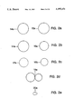
- FIG. 2 is a five part figure showing, in magnified scale, cross-sectional views of the fibers illustrated in the various steps shown in FIG. 1 wherein:
- FIG. 2a illustrates the cross-sections of the etched fibers at the points indicated as 14 and 15 in FIG. 1a;
- FIG. 2b shows shows the cross-section at the center of the tapered region 16 shown in FIG. 1b;
- FIG. 2c shows the cross-sections of the two tapered fibers shown in FIG. 1c;
- FIG. 2d shows the cross-section as it might appear at any point in the region of contact 18 shown in FIG. 1d;
- FIG. 2e shows the cross-section of a fused fiber pair within the elongated region shown in FIG. 1e.
- FIG. 3 a graphical presentation of data comparing the coupling ratio wavelength response of a typical short-draw Delta-B wideband coupler shown by the curve intersecting the white blocks, to the wavelength response of a coupler of the invention, shown by the curve intersecting the black blocks. Coupling ratio in percent is shown on the vertical axis. Wavelength is shown on the horizontal axis.
- FIG. 4 is a graphical presentation of data showing the coupling ratio on the vertical axis versus wavelength on the horizontal axis of a 1.2% wideband coupler of the invention.
- FIG. 5 a graphical presentation of data showing the on the vertical axis versus wavelength on axis of a 4.8% wideband coupler of the invention.
- FIG. 6 is a graphical presentation of data showing the coupling ratio on the vertical axis versus wavelength on the horizontal axis of an 11.8% wideband coupler of the invention.
- FIG. 7 is a graphical presentation of data showing the ratio on the vertical axis versus wavelength on the horizontal axis of a 20.2% wideband coupler of the invention.
- FIG. 8 is a graphical presentation, for a prior art coupler, of the coupling ratio on the vertical axis versus wavelength on the horizontal axis of a 48% wideband coupler.
- FIG. 9 is a graphical presentation of data showing the excess loss in dB, on the vertical axis, versus coupling ratio, on the horizontal axis, as measured in couplers of the invention shown by the black circles with the trend shown by the black line.
- FIG. 10 is a two part figure.
- FIG. 10a schematically illustrates mounting a coupler to a substrate in a manner to relieve stress from the coupling region.
- FIG. 10a shows a packaged coupler with input and output fibers arranged at right angles.
- FIG. 11 is a four part figure that illustrates cross sectional views of the coupling region prior to fusion of 4 embodiments each coupling more than two fibers.
- FIG. 11a illustrates seven fibers of the same diameter wherein six fibers are disposed in a radially symmetric, azimuthally periodic manner around a central fiber.
- FIG. 11b illustrates the cross section of a coupling region as it might appear before fusion wherein eight fibers are disposed in an orderly manner about a central fiber of larger diameter.
- FIG. 11c illustrates five fibers of different diameter grouped in a random manner.
- FIG. 11d shows 4 fibers of the same diameter grouped in a random manner.
- FIG. 12 is a graphical presentation of data showing the on the vertical axis versus wavelength horizontal axis of a 1 ⁇ 4, 10%, 20%, 30%, 40% wideband star coupler of the invention.
- FIG. 1a shows two identical singlemode optical fibers 10, 11 from which, over a portion of length, the protective jacket 12, 13 has been removed and which have been subsequently etched in regions 14, 15 to provide sections of constant, reduced thickness.
- the fibers may for instance be standard singlemode depressed clad fibers available from AT&T, with a portion of the outer clad etched away.
- One of the fibers is then separately heated and drawn by means familiar to one skilled in the art as shown in FIG. 1b, or both of the fibers are separately heated and drawn different amounts thus forming tapered regions 16, 17 shown in FIG. 1c.
- the tapered regions 16 and 17 have different diameters. In each case therefore the fibers are different in a characteristic that, as understood by those familiar with the physics of such systems, limits the amount the antisymmetric propagation mode will be excited in the resulting coupler.
- the fibers e.g., as depicted in FIG. 1b are then wrapped around each other creating a region of contact 18 shown generally in FIG. 1d and both are placed in a drawing apparatus not shown.
- a stationary heat source is then applied to the region of contact and the drawing apparatus is activated so as to elongate the heated region indicated as 19 in FIG. 1d.
- light of a selected wavelength can be passed through of the fibers and the coupling ratio can be monitored by sensing the excitation in both fibers. The coupling ratio is observed to oscillate as drawing proceeds.
- the coupler After the coupler is drawn through many coupling ratio cycles (overdrawn) the coupling ratio is observed to stabilize, attributable to cutoff of the antisymmetric mode, i.e., the coupler begins behaving essentially like a single fiber, guiding substantially only the symmetric mode.
- the resulting fused tapered structure is diagrammatically illustrated as 20 of FIG. 1e.
- heat may be applied at the center of the contacting region or may be offset substantially from the center.
- the drawing stages may be made to move apart at substantially the same speed or at different speeds.
- the reduced diameter fibers may be aligned so that the smallest diameter of one fiber contacts the smallest diameter of the second fiber, or the smallest diameter regions may be offset substantially. Location of the heat source, relation of drawing speeds, and longitudinal alignment of tapered regions have predeterminable effects on the final coupling ratio and wavelength stability.
- FIG. 2 shows cross-sectional views of the fibers illustrated in the various steps shown in FIG. 1.
- the cross-sections of the etched fibers at the points indicated as 14 and 15 in FIG. 1 are shown in FIG. 2a as 14a and 15a respectively.
- FIG. 2b shows the cross-section 16a at the center of the tapered region 16 shown in FIG. 1b compared to the cross-section 14a of the untapered fiber 14 of FIG. 1.
- FIG. 2c are shown the cross-sections 17a and 16b of the two tapered fibers shown in FIG. 1c.
- FIG. 2d shows the cross-section 18a as it might appear at any point in the region of contact 18 shown in FIG. 1d.
- FIG. 2e shows the cross-section 20a of the fused fiber pair within the elongated region 20 shown in FIG. 1e.
- the method of predetermining the tapered fiber diameter prior to fusion comprises drawing the etched or unetched fiber or fibers a certain distance.
- the original diameter of the fiber is known to high accuracies.
- Etched fibers can be produced with very highly repeatable etched diameters by careful control of the etching conditions. Therefore, with either etched or unetched fibers, the diameter before pre-tapering is known.
- data is tabulated relating the length of the pre-taper draw to the final coupling ratio achieved for a variety of fiber pre-taper lengths.
- the pre-taper length is considered to be the distance the fiber is elongated in the diameter reduction step.
- This value can be read with 1 micron resolution from several commercially available translation stage controllers.
- the final coupling ratio obtained by using a specifically elongated fiber is useful in a controlled manufacturing operation. Consequently, a set of pre-fusion taper draw lengths are collected and used thereafter to control the final coupling ratio as exemplified in Table 1.
- FIG. 3 compares the wavelength response of a typical short-draw Delta-B wideband coupler of prior art shown by the curve 30 intersecting the white blocks, to the wavelength response of a coupler of the invention, shown by the curve 31 intersecting the black blocks.
- the prior art Delta B wideband coupler Over the 1200 to 1600 nm optical bandwidth indicated on the horizontal axis, the prior art Delta B wideband coupler has coupling ratio, indicated on the vertical axis, of about 11.4+/-3.5 percent. Over the same wavelength range, the coupler of the invention is seen to have a coupling ratio of 11.2+/-0.8 percent.
- the coupler of the invention was made using a pre-draw taper of 640 um according to Table 1.
- FIGS. 4 through 7 the wavelength response of four other typical couplers drawn according the empirical pre-fusion draw lengths given in Table 1 above are shown in FIGS. 4 through 7.
- the coupler of FIG. 4 e.g., was made using two fibers etched to a diameter of 40 um. One of the fibers was subsequently drawn 960 um prior to fusion. The fusion draw was continued, as explained herein above, until the coupling ratio became stable at the value of about 1.2 percent shown in FIG. 4.
- the coupler wavelength responses shown in FIGS. 5, 6, and 7 relate to couplers made from fibers etched to 40 um, one each of which was drawn respectively 900, 640, and 400 um. Table 2 summarizes the average coupling ratio and excess loss of each of these 4 typical couplers of the invention.
- the coupler of FIG. 8 was made of etched fibers that were not subject to a pre-fusion draw, i.e., the fibers used to make that nominally 48% coupler were of substantially identical diameters, with identical propagation constants, in this way being similar to the fibers used in the prior art experiment of Bilodeau, et al., cited above.
- the extended drawing technique was used.
- Table 2 it is of particular interest to note the distinctions between the couplers made according to the invention and the coupler of FIG. 8 made by extended drawing of identical fibers.
- the couplers made according to the invention have predeterminable coupling ratios substantially below 50 percent.
- the coupler of FIG. 8, drawn from identical fibers has coupling ratio near 50%.
- couplers made according to the invention have acceptably low excess loss for most practical applications.
- a coupler made from identical fibers, as expected, has about 50% excess loss, which for most applications is not practical.
- the favorable excess loss characteristics of the couplers made according to the present invention are attributed to the fact that, by starting with fibers having preselected, different propagation constants, achieved here by differing diameters, the amount of excitation in the first antisymmetric higher order mode is kept substantially below 50% and indeed preferably below 30%, and in many instances far below that. Therefore, when the coupler is "overdrawn" to the point where the antisymmetric mode is cut off, only the limited energy in the asymmetric mode is lost, while the predominant portion of the energy is preserved, thus enabling a coupler with practically acceptable loss characteristics to be realized.
- the wideband phenomenon observed in the prior art experiment reported above and illustrated in FIG. 8 did not produce coupler of general practicality, the novel combination of limiting the energization of the antisymmetric mode with the long or overdrawn technique just described can lead to a wide variety of practical couplers.
- FIG. 9 shows an excess loss curve with excess loss Li expressed in dB indicated on the vertical axis of FIG. 9, versus coupling ratio Cri indicated on the horizontal axis.
- the black circles plot the average measured excess losses from couplers of the invention and the line 91 shows the trend. Excess loss decreases with decreasing coupling ratio and decrease in excitation of the antisymmetric mode in couplers made according to the invention.
- couplers of the invention having low coupling ratio, for use, e.g., in tapped bus distribution systems, can reliably be made to have low excess loss in addition to environmental stability and truly wideband coupling response.
- Couplers may find practical utility in applications where there is a relatively large amount of light energy available, where a tap with extremely stable coupling characteristics is desired.
- An example is the use of a powerful laser diode in a context where it is desired to split the light at an assured constant ratio despite variations in polarization or wavelength.
- couplers having more restricted coupling ratios With couplers having more restricted coupling ratios, excess loss of less than 1.5 dB can be obtained.
- Such couplers are suitable for systems e.g., employing lower power lasers as the light source, where the power budgets are tighter.
- the invention makes possible low coupling ratio splitters and couplers with excess loss less than 1 dB, that can find practical applications in feedback systems where a small amount of power is fed back to control a highly stabilized light source.
- the diameter of the fused coupling region indicated in cross section, e.g., by 20a in FIG. 2, has cross sectional dimensions in the range of a few microns.
- This thin coupling region can be bent without affecting the optical properties of the coupler.
- the fused coupling region may be secured to a substrate with constituent fibers thereof in essentially tension relaxed condition. This manner of mounting is illustrated schematically in FIG. 10a.
- Two fibers 40 are fused and drawn according to the methods described herein and are then attached, e.g., by adhesive applied to regions denoted 41 in FIG. 10a, to a substrate 42.
- FIG. 1Oa A two fiber coupler of the first aspect of the invention is illustrated in FIG. 1Oa.
- FIG. 11 illustrates cross sectional views of the coupling region prior to fusion of four embodiments each coupling more than two fibers.
- FIG. 11a illustrates seven fibers of the same diameter wherein six fibers 50, are disposed in a radially symmetric, azimuthally periodic manner around a central fiber 51. This is an orderly grouping of fibers of the same diameter.
- FIG. 11b illustrates the cross section of a coupling region as it might appear before fusion wherein eight fibers 53 are disposed in an orderly manner about a central fiber 54 of larger diameter.
- FIG. 11c illustrates five fibers of different diameter grouped in a random manner.
- FIG. 11d shows 4 fibers of the same diameter grouped in a random manner.
- Couplers having more than two output ports can, in general, be made to distribute light into each output fiber in inverse proportion to the number of coupled fibers. I.e., if a coupler is made with N fibers fused and elongated, and if optical power P is launched into one of the N fibers, then, neglecting excess loss, each of the N output fibers can be made to carry optical power substantially equal to P/N. Therefore, the coupling ratio decreases as the number N of fibers coupled increases. For couplers made in accordance with broad aspects of the present invention, the excess loss decreases as the coupling ratio decreases.
- an embodiment of the invention having a large number of fibers coupled, which has small coupling ratios at each output and small excess loss.
- FIG. 12 shows wideband coupling ratio wavelength response of an experimental 4 ⁇ 4 coupler of the invention, made using the long-draw techniques that have been described.
- the diameters of all four fibers were equal. Prior to fusion the fibers were arranged substantially as shown in FIG. 11d. Coupling ratios were measured around 1300 and 1550 nm. It can be seen that the coupling ratios to each of the four outputs are essentially 10%, 20%, 30%, and 40% as shown by the lines labelled 101, 102, 103, and 104.
- This coupler demonstrated an average excess loss of about 33%. Long-draw couplers are expected to have 50% excess loss.
- the data of FIG. 12 indicate that the construction and arrangement of the multiple fibers here also limits the excitation of antisymmetric mode power with resultant favorable excess loss characteristics (substantially less than 50% excess loss).
- a 1 ⁇ N coupler has very flat wavelength response, a convenient range of coupling ratios, acceptable excess loss, virtual insensitivity to thermal and polarization variations, and can be made economically without necessarily requiring the labor and special fixtures needed to ensure symmetrical fiber placement before fusion.
Landscapes
- Physics & Mathematics (AREA)
- General Physics & Mathematics (AREA)
- Optics & Photonics (AREA)
- Optical Couplings Of Light Guides (AREA)
Abstract
Description
              TABLE 1
______________________________________
Final coupling ratio as a result of
pre-fusion taper draw length.
Pre-fusion-Taper Draw Length (um)
                    Final Coupling Ratio (%)
______________________________________
960                  1.2
900                  4.8
640                 11.8
400                 20.2
______________________________________
              TABLE 2
______________________________________
                        Average
Figure     Pre-fusion   coupling Excess
Number     Draw Length  ratio    Loss
______________________________________
4          960 um        1.2%    0.30%
5          900 um        4.8%    0.64%
6          640 um       11.8%    0.62%
7          400 um       20.2%    0.70%
8 (prior art)
            0 um        48.0%    55.30%
______________________________________
Claims (16)
Priority Applications (2)
| Application Number | Priority Date | Filing Date | Title |
|---|---|---|---|
| US07/628,597 US5195151A (en) | 1990-12-17 | 1990-12-17 | Optical fiber couplers and methods of their manufacture |
| PCT/US1991/009485 WO1992011552A1 (en) | 1990-12-17 | 1991-12-17 | Optical fiber couplers and methods of their manufacture |
Applications Claiming Priority (1)
| Application Number | Priority Date | Filing Date | Title |
|---|---|---|---|
| US07/628,597 US5195151A (en) | 1990-12-17 | 1990-12-17 | Optical fiber couplers and methods of their manufacture |
Publications (1)
| Publication Number | Publication Date |
|---|---|
| US5195151A true US5195151A (en) | 1993-03-16 |
Family
ID=24519556
Family Applications (1)
| Application Number | Title | Priority Date | Filing Date |
|---|---|---|---|
| US07/628,597 Expired - Fee Related US5195151A (en) | 1990-12-17 | 1990-12-17 | Optical fiber couplers and methods of their manufacture |
Country Status (2)
| Country | Link |
|---|---|
| US (1) | US5195151A (en) |
| WO (1) | WO1992011552A1 (en) |
Cited By (26)
| Publication number | Priority date | Publication date | Assignee | Title |
|---|---|---|---|---|
| US5309536A (en) * | 1991-06-18 | 1994-05-03 | Sumitomo Electric Industries, Ltd. | Process for producing an optical fiber coupler |
| US5373572A (en) * | 1990-07-18 | 1994-12-13 | British Telecommunications Public Limited Company | Method of forming multiport optical fibre coupler and the coupler so formed |
| US5479550A (en) * | 1993-05-13 | 1995-12-26 | Olympus Optical Co., Ltd. | Image fiber |
| US5486921A (en) * | 1994-04-05 | 1996-01-23 | Litton Systems, Inc. | Optimum coupler configuration for fiber optic rate gyroscope using [3×] coupler |
| US5636022A (en) * | 1994-07-29 | 1997-06-03 | Litton Systems, Inc. | Closed loop unmodulated fiber optic rate gyroscope with 3×3 coupler and method |
| US5644666A (en) * | 1995-12-22 | 1997-07-01 | Gould Electronics Inc. | Broadband optical fiber coupler and method of making |
| US5703976A (en) * | 1994-11-15 | 1997-12-30 | Northern Telecom Limited | Wavelength resonant fused fibre coupler |
| US5777737A (en) * | 1994-07-22 | 1998-07-07 | Litton Systems, Inc. | Apparatus and method for processing signals output from fiber optic rate gyroscope having 3×3 coupler |
| US5796885A (en) * | 1996-05-09 | 1998-08-18 | Gonthier; Francois | 3×3 waveguide coupler for bidirectional dual wavelength transmission and signal sampling and method for making the same |
| US5848208A (en) * | 1996-07-25 | 1998-12-08 | Fujikura Ltd. | Optical-fiber coupler and manufacturing process therefor |
| US5956447A (en) * | 1996-05-07 | 1999-09-21 | Univ Central Florida | Device and method for image acquisition through multi-mode fiber |
| US6062743A (en) * | 1997-06-09 | 2000-05-16 | Telefonaktiebolaget Lm Ericsson | Splicing different optical fiber types |
| US6148129A (en) * | 1993-01-15 | 2000-11-14 | E-Tek Dynamics, Inc. | Broad bandwidth, single mode fiber optic coupler and method of manufacture |
| EP1217400A1 (en) * | 2000-12-22 | 2002-06-26 | Corning O.T.I. S.p.A. | Method for making splices between two optical fibres which are different from each other |
| WO2002052318A1 (en) * | 2000-12-22 | 2002-07-04 | Corning O.T.I Spa | Method for making splices between two optical fibres which are different from each other |
| US6466717B1 (en) * | 1999-01-06 | 2002-10-15 | Itf Optical Technologies Inc. | Optical fiber filters and method of making the same |
| US20020176672A1 (en) * | 2001-05-24 | 2002-11-28 | Fiber Optic Network Solutions Corp. | Optical fiber fusion system |
| US6614961B2 (en) * | 2000-02-28 | 2003-09-02 | The Korea Advanced Institute Of Science And Technology | Method of fabricating a fused-type mode-selective directional coupler |
| US20060133734A1 (en) * | 2004-12-16 | 2006-06-22 | Honeywell International Inc. | Optical coupler for measuring wavelength |
| US20070211777A1 (en) * | 2005-12-12 | 2007-09-13 | Sergey Simavoryan | Laser diode array beam translator |
| US20080232748A1 (en) * | 2005-10-11 | 2008-09-25 | Qinetiq Limited | Fibre-Optic Package and Method of Making the Same |
| US20090175575A1 (en) * | 2007-11-19 | 2009-07-09 | Fujikura Ltd. | Multimode optical coupler |
| US20100158443A1 (en) * | 2008-12-24 | 2010-06-24 | Fujitsu Limited | Optical semiconductor device, manufacturing method thereof and optical transmission device |
| EP2618191A3 (en) * | 2012-01-20 | 2014-07-09 | LASER ZENTRUM HANNOVER e.V. | Coupling arrangement for non-axial transfer of electromagnetic radiation |
| CN111095692A (en) * | 2017-09-01 | 2020-05-01 | 三菱电机株式会社 | Laser device |
| US20210266066A1 (en) * | 2020-02-24 | 2021-08-26 | Ciena Corporation | Loss-based wavelength meter |
Families Citing this family (1)
| Publication number | Priority date | Publication date | Assignee | Title |
|---|---|---|---|---|
| CA2123757C (en) * | 1994-05-17 | 2002-06-25 | Francois Gonthier | Method for making optical waveguide couplers with low wavelength sensitivity and couplers thereby produced |
Citations (7)
| Publication number | Priority date | Publication date | Assignee | Title |
|---|---|---|---|---|
| WO1987000934A1 (en) * | 1985-07-30 | 1987-02-12 | British Telecommunications Public Limited Company | Optical fused couplers |
| US4763977A (en) * | 1985-01-09 | 1988-08-16 | Canadian Patents And Development Limited-Societe | Optical fiber coupler with tunable coupling ratio and method of making |
| EP0293289A2 (en) * | 1987-05-21 | 1988-11-30 | Amphenol Corporation | Wavelength independent coupler and method of manufacture thereof |
| US4895423A (en) * | 1988-01-11 | 1990-01-23 | Canadian Patents And Development Limited | Fabrication technique for low-loss fused taper directional couplers and pressure sensor produced thereby |
| US4900119A (en) * | 1988-04-01 | 1990-02-13 | Canadian Patents & Development Ltd. | Wavelength selective optical devices using optical directional coupler |
| US5004316A (en) * | 1986-01-09 | 1991-04-02 | Her Majesty The Queen In Right Of Canada, As Represented By The Minister Of Communications | Coupler fabrication techniques for dissimilar fibers |
| US5054874A (en) * | 1990-12-17 | 1991-10-08 | Her Majesty The Queen In Right Of Canada, As Represented By The Minister Of Communications | Coupler fabrication techniques for dissimilar fibers |
-
1990
- 1990-12-17 US US07/628,597 patent/US5195151A/en not_active Expired - Fee Related
-
1991
- 1991-12-17 WO PCT/US1991/009485 patent/WO1992011552A1/en active Application Filing
Patent Citations (9)
| Publication number | Priority date | Publication date | Assignee | Title |
|---|---|---|---|---|
| US4763977A (en) * | 1985-01-09 | 1988-08-16 | Canadian Patents And Development Limited-Societe | Optical fiber coupler with tunable coupling ratio and method of making |
| WO1987000934A1 (en) * | 1985-07-30 | 1987-02-12 | British Telecommunications Public Limited Company | Optical fused couplers |
| US4798436A (en) * | 1985-07-30 | 1989-01-17 | British Telecommunications, Plc | Optical fused couplers |
| US5004316A (en) * | 1986-01-09 | 1991-04-02 | Her Majesty The Queen In Right Of Canada, As Represented By The Minister Of Communications | Coupler fabrication techniques for dissimilar fibers |
| EP0293289A2 (en) * | 1987-05-21 | 1988-11-30 | Amphenol Corporation | Wavelength independent coupler and method of manufacture thereof |
| US4822126A (en) * | 1987-05-21 | 1989-04-18 | Amphenol Corporation | Wavelength independent coupler and method of manufacture thereof |
| US4895423A (en) * | 1988-01-11 | 1990-01-23 | Canadian Patents And Development Limited | Fabrication technique for low-loss fused taper directional couplers and pressure sensor produced thereby |
| US4900119A (en) * | 1988-04-01 | 1990-02-13 | Canadian Patents & Development Ltd. | Wavelength selective optical devices using optical directional coupler |
| US5054874A (en) * | 1990-12-17 | 1991-10-08 | Her Majesty The Queen In Right Of Canada, As Represented By The Minister Of Communications | Coupler fabrication techniques for dissimilar fibers |
Non-Patent Citations (8)
| Title |
|---|
| D. B. Mortimore, "Monolithic Wavelength-Flattened 1×7 Single-Mode Fused Coupler", Electronics Letter, vol. 25, No. 9, Apr. 1989. |
| D. B. Mortimore, "Theory and fabrication of 4×4 single-mode fused optical fiber couplers", Applied Optics, vol. 29, No. 3, Jan. 20, 1990, pp. 371-374. |
| D. B. Mortimore, "Wavelength-Flattened Fused Couplers", Electron. Letter, 21, 742, 1985. |
| D. B. Mortimore, Monolithic Wavelength Flattened 1 7 Single Mode Fused Coupler , Electronics Letter, vol. 25, No. 9, Apr. 1989. * |
| D. B. Mortimore, Theory and fabrication of 4 4 single mode fused optical fiber couplers , Applied Optics, vol. 29, No. 3, Jan. 20, 1990, pp. 371 374. * |
| D. B. Mortimore, Wavelength Flattened Fused Couplers , Electron. Letter, 21, 742, 1985. * |
| F. Bilodeau, et al., "Compact, low-loss, fused biconical taper couplers: overcoupled operation and antisymmetric supermode cutoff", Optics Letters, vol. 12, No. 8, Aug. 1987, pp. 634-636. |
| F. Bilodeau, et al., Compact, low loss, fused biconical taper couplers: overcoupled operation and antisymmetric supermode cutoff , Optics Letters, vol. 12, No. 8, Aug. 1987, pp. 634 636. * |
Cited By (33)
| Publication number | Priority date | Publication date | Assignee | Title |
|---|---|---|---|---|
| US5373572A (en) * | 1990-07-18 | 1994-12-13 | British Telecommunications Public Limited Company | Method of forming multiport optical fibre coupler and the coupler so formed |
| US5309536A (en) * | 1991-06-18 | 1994-05-03 | Sumitomo Electric Industries, Ltd. | Process for producing an optical fiber coupler |
| US6148129A (en) * | 1993-01-15 | 2000-11-14 | E-Tek Dynamics, Inc. | Broad bandwidth, single mode fiber optic coupler and method of manufacture |
| US5479550A (en) * | 1993-05-13 | 1995-12-26 | Olympus Optical Co., Ltd. | Image fiber |
| US5486921A (en) * | 1994-04-05 | 1996-01-23 | Litton Systems, Inc. | Optimum coupler configuration for fiber optic rate gyroscope using [3×] coupler |
| US5777737A (en) * | 1994-07-22 | 1998-07-07 | Litton Systems, Inc. | Apparatus and method for processing signals output from fiber optic rate gyroscope having 3×3 coupler |
| US5636022A (en) * | 1994-07-29 | 1997-06-03 | Litton Systems, Inc. | Closed loop unmodulated fiber optic rate gyroscope with 3×3 coupler and method |
| US5703976A (en) * | 1994-11-15 | 1997-12-30 | Northern Telecom Limited | Wavelength resonant fused fibre coupler |
| US5644666A (en) * | 1995-12-22 | 1997-07-01 | Gould Electronics Inc. | Broadband optical fiber coupler and method of making |
| US5956447A (en) * | 1996-05-07 | 1999-09-21 | Univ Central Florida | Device and method for image acquisition through multi-mode fiber |
| US5796885A (en) * | 1996-05-09 | 1998-08-18 | Gonthier; Francois | 3×3 waveguide coupler for bidirectional dual wavelength transmission and signal sampling and method for making the same |
| US5848208A (en) * | 1996-07-25 | 1998-12-08 | Fujikura Ltd. | Optical-fiber coupler and manufacturing process therefor |
| US6062743A (en) * | 1997-06-09 | 2000-05-16 | Telefonaktiebolaget Lm Ericsson | Splicing different optical fiber types |
| US6466717B1 (en) * | 1999-01-06 | 2002-10-15 | Itf Optical Technologies Inc. | Optical fiber filters and method of making the same |
| US6614961B2 (en) * | 2000-02-28 | 2003-09-02 | The Korea Advanced Institute Of Science And Technology | Method of fabricating a fused-type mode-selective directional coupler |
| EP1217400A1 (en) * | 2000-12-22 | 2002-06-26 | Corning O.T.I. S.p.A. | Method for making splices between two optical fibres which are different from each other |
| WO2002052318A1 (en) * | 2000-12-22 | 2002-07-04 | Corning O.T.I Spa | Method for making splices between two optical fibres which are different from each other |
| US20020176672A1 (en) * | 2001-05-24 | 2002-11-28 | Fiber Optic Network Solutions Corp. | Optical fiber fusion system |
| US6827508B2 (en) | 2001-05-24 | 2004-12-07 | Fiber Optic Network Solutions Corporation | Optical fiber fusion system |
| US20060133734A1 (en) * | 2004-12-16 | 2006-06-22 | Honeywell International Inc. | Optical coupler for measuring wavelength |
| US7272280B2 (en) | 2004-12-16 | 2007-09-18 | Honeywell International Inc. | Optical coupler for measuring wavelength |
| US20080232748A1 (en) * | 2005-10-11 | 2008-09-25 | Qinetiq Limited | Fibre-Optic Package and Method of Making the Same |
| US20070211777A1 (en) * | 2005-12-12 | 2007-09-13 | Sergey Simavoryan | Laser diode array beam translator |
| US7693367B2 (en) * | 2007-11-19 | 2010-04-06 | Fujikura Ltd. | Multi-mode optical coupler |
| US20090175575A1 (en) * | 2007-11-19 | 2009-07-09 | Fujikura Ltd. | Multimode optical coupler |
| US20100158443A1 (en) * | 2008-12-24 | 2010-06-24 | Fujitsu Limited | Optical semiconductor device, manufacturing method thereof and optical transmission device |
| US8358885B2 (en) * | 2008-12-24 | 2013-01-22 | Fujitsu Limited | Optical semiconductor device, manufacturing method thereof and optical transmission device |
| EP2618191A3 (en) * | 2012-01-20 | 2014-07-09 | LASER ZENTRUM HANNOVER e.V. | Coupling arrangement for non-axial transfer of electromagnetic radiation |
| EP3086148A3 (en) * | 2012-01-20 | 2017-01-18 | Laser Zentrum Hannover E.V. | Coupling arrangement for non-axial transfer of electromagnetic radiation |
| CN111095692A (en) * | 2017-09-01 | 2020-05-01 | 三菱电机株式会社 | Laser device |
| CN111095692B (en) * | 2017-09-01 | 2021-10-26 | 三菱电机株式会社 | Laser device |
| US20210266066A1 (en) * | 2020-02-24 | 2021-08-26 | Ciena Corporation | Loss-based wavelength meter |
| US11683092B2 (en) * | 2020-02-24 | 2023-06-20 | Ciena Corporation | Loss-based wavelength meter |
Also Published As
| Publication number | Publication date |
|---|---|
| WO1992011552A1 (en) | 1992-07-09 |
Similar Documents
| Publication | Publication Date | Title |
|---|---|---|
| US5195151A (en) | Optical fiber couplers and methods of their manufacture | |
| CA2535472C (en) | Multimode fiber outer cladding coupler for multi-clad fibers | |
| US5452393A (en) | Miniature fiberoptic bend device and method | |
| KR100647378B1 (en) | Photonic Crystal Fibers and Improvements in Photonic Crystal Fibers | |
| CN101794955B (en) | A kind of preparation method of all-fiber laser synthesis device | |
| US5121452A (en) | Fiber optic power splitter | |
| US4482203A (en) | Adjustable coupling device for a fiber-optic power divider | |
| WO2014091065A1 (en) | Fiber optic mode scrambler and a method of manufacturing thereof | |
| KR20010084624A (en) | Method of fabricating fused-type mode selective coupler | |
| AU646062B2 (en) | Optical fibre coupler | |
| US5883992A (en) | Method for making optical waveguide couplers with low wavelength sensitivity and couplers thereby produced | |
| US5644666A (en) | Broadband optical fiber coupler and method of making | |
| AU644680B2 (en) | Miniature fiberoptic bend device and method | |
| CN119395815A (en) | A structured light generating device based on multi-core optical fiber combiner and its preparation method | |
| AU644680C (en) | Miniature fiberoptic bend device and method | |
| Godbout et al. | Wavelength independent fused fibre couplers based on group velocity equalisation | |
| HK112097A (en) | Optical fibre coupler | |
| JPH02141707A (en) | Fiber type coupler and its manufacturing method |
Legal Events
| Date | Code | Title | Description |
|---|---|---|---|
| AS | Assignment |
Owner name: ASTER CORPORATION, MILFORD, MASSACHUSETTS A CORP. Free format text: ASSIGNMENT OF ASSIGNORS INTEREST.;ASSIGNORS:CAMPBELL, DANIEL R. JR.;STOWE, DAVID W.;REEL/FRAME:005672/0463 Effective date: 19910109 |
|
| AS | Assignment |
Owner name: CHEMICAL BANK, NEW YORK Free format text: SECURITY INTEREST;ASSIGNOR:ASTER CORPORATION;REEL/FRAME:006599/0663 Effective date: 19930624 |
|
| CC | Certificate of correction | ||
| AS | Assignment |
Owner name: FOOTHILL CAPITAL CORP. Free format text: ASSIGNMENT OF ASSIGNORS INTEREST;ASSIGNOR:CHEMICAL BANK;REEL/FRAME:007403/0147 Effective date: 19941128 |
|
| FEPP | Fee payment procedure |
Free format text: PAYOR NUMBER ASSIGNED (ORIGINAL EVENT CODE: ASPN); ENTITY STATUS OF PATENT OWNER: LARGE ENTITY Free format text: PAT HLDR NO LONGER CLAIMS SMALL ENT STAT AS SMALL BUSINESS (ORIGINAL EVENT CODE: LSM2); ENTITY STATUS OF PATENT OWNER: LARGE ENTITY |
|
| AS | Assignment |
Owner name: AUGAT, INC., MASSACHUSETTS Free format text: ASSIGNMENT OF ASSIGNORS INTEREST;ASSIGNOR:ASTER CORPORATION;REEL/FRAME:007869/0296 Effective date: 19960313 |
|
| FPAY | Fee payment |
Year of fee payment: 4 |
|
| AS | Assignment |
Owner name: THOMAS & BETTS INTERNATIONAL, INC., NEVADA Free format text: ASSIGNMENT OF ASSIGNORS INTEREST;ASSIGNOR:AUGAT INC.;REEL/FRAME:009342/0330 Effective date: 19980630 |
|
| FEPP | Fee payment procedure |
Free format text: PAYER NUMBER DE-ASSIGNED (ORIGINAL EVENT CODE: RMPN); ENTITY STATUS OF PATENT OWNER: LARGE ENTITY Free format text: PAYOR NUMBER ASSIGNED (ORIGINAL EVENT CODE: ASPN); ENTITY STATUS OF PATENT OWNER: LARGE ENTITY |
|
| FPAY | Fee payment |
Year of fee payment: 8 |
|
| AS | Assignment |
Owner name: ALCOA FUJIKURA LIMITED, TENNESSEE Free format text: ASSIGNMENT OF ASSIGNORS INTEREST;ASSIGNOR:THOMAS & BETTS INTERNATIONAL, INC.;REEL/FRAME:012002/0927 Effective date: 20010618 |
|
| REMI | Maintenance fee reminder mailed | ||
| LAPS | Lapse for failure to pay maintenance fees | ||
| STCH | Information on status: patent discontinuation |
Free format text: PATENT EXPIRED DUE TO NONPAYMENT OF MAINTENANCE FEES UNDER 37 CFR 1.362 |
|
| FP | Lapsed due to failure to pay maintenance fee |
Effective date: 20050316 |
|
| AS | Assignment |
Owner name: WELLS FARGO CAPITAL FINANCE, LLC, AS AGENT, CALIFO Free format text: SECURITY INTEREST;ASSIGNOR:AEES INC.;REEL/FRAME:026152/0083 Effective date: 20101221 |