EP0779839B1 - A device for separating extremely fine particles from air - Google Patents
A device for separating extremely fine particles from air Download PDFInfo
- Publication number
- EP0779839B1 EP0779839B1 EP95922055A EP95922055A EP0779839B1 EP 0779839 B1 EP0779839 B1 EP 0779839B1 EP 95922055 A EP95922055 A EP 95922055A EP 95922055 A EP95922055 A EP 95922055A EP 0779839 B1 EP0779839 B1 EP 0779839B1
- Authority
- EP
- European Patent Office
- Prior art keywords
- carrier
- air
- strips
- fibres
- filter
- Prior art date
- Legal status (The legal status is an assumption and is not a legal conclusion. Google has not performed a legal analysis and makes no representation as to the accuracy of the status listed.)
- Expired - Lifetime
Links
- 239000010419 fine particle Substances 0.000 title claims description 3
- 238000005452 bending Methods 0.000 claims description 2
- 230000030279 gene silencing Effects 0.000 claims description 2
- 238000000926 separation method Methods 0.000 claims description 2
- 239000002245 particle Substances 0.000 abstract description 29
- 239000000835 fiber Substances 0.000 description 9
- 239000004033 plastic Substances 0.000 description 8
- 239000000463 material Substances 0.000 description 7
- 238000004519 manufacturing process Methods 0.000 description 6
- 230000005684 electric field Effects 0.000 description 5
- 239000011888 foil Substances 0.000 description 5
- 230000035508 accumulation Effects 0.000 description 4
- 238000009825 accumulation Methods 0.000 description 4
- 230000000694 effects Effects 0.000 description 4
- 239000004743 Polypropylene Substances 0.000 description 3
- 238000010276 construction Methods 0.000 description 3
- 238000011161 development Methods 0.000 description 3
- 230000005611 electricity Effects 0.000 description 3
- 239000002861 polymer material Substances 0.000 description 3
- -1 polypropylene Polymers 0.000 description 3
- 229920001155 polypropylene Polymers 0.000 description 3
- 230000003584 silencer Effects 0.000 description 3
- 230000003068 static effect Effects 0.000 description 3
- 238000004026 adhesive bonding Methods 0.000 description 2
- 230000008901 benefit Effects 0.000 description 2
- 238000004140 cleaning Methods 0.000 description 2
- 239000000470 constituent Substances 0.000 description 2
- 238000005520 cutting process Methods 0.000 description 2
- 150000002500 ions Chemical class 0.000 description 2
- 238000005304 joining Methods 0.000 description 2
- 238000011144 upstream manufacturing Methods 0.000 description 2
- 241000446313 Lamella Species 0.000 description 1
- 241001465754 Metazoa Species 0.000 description 1
- 230000009471 action Effects 0.000 description 1
- 238000005054 agglomeration Methods 0.000 description 1
- 230000002776 aggregation Effects 0.000 description 1
- 238000003915 air pollution Methods 0.000 description 1
- 238000004887 air purification Methods 0.000 description 1
- 230000015572 biosynthetic process Effects 0.000 description 1
- 230000001419 dependent effect Effects 0.000 description 1
- 239000002657 fibrous material Substances 0.000 description 1
- 238000001914 filtration Methods 0.000 description 1
- 239000003365 glass fiber Substances 0.000 description 1
- 239000003292 glue Substances 0.000 description 1
- 239000008187 granular material Substances 0.000 description 1
- 230000006872 improvement Effects 0.000 description 1
- 238000012423 maintenance Methods 0.000 description 1
- 239000002184 metal Substances 0.000 description 1
- 238000000034 method Methods 0.000 description 1
- 239000011859 microparticle Substances 0.000 description 1
- 238000012986 modification Methods 0.000 description 1
- 230000004048 modification Effects 0.000 description 1
- 230000010287 polarization Effects 0.000 description 1
- 239000011148 porous material Substances 0.000 description 1
- 239000002244 precipitate Substances 0.000 description 1
- 230000008569 process Effects 0.000 description 1
- 238000011084 recovery Methods 0.000 description 1
- 230000000284 resting effect Effects 0.000 description 1
- 239000000126 substance Substances 0.000 description 1
- 238000012360 testing method Methods 0.000 description 1
- BFKJFAAPBSQJPD-UHFFFAOYSA-N tetrafluoroethene Chemical group FC(F)=C(F)F BFKJFAAPBSQJPD-UHFFFAOYSA-N 0.000 description 1
- 239000012905 visible particle Substances 0.000 description 1
Images


Classifications
-
- B—PERFORMING OPERATIONS; TRANSPORTING
- B03—SEPARATION OF SOLID MATERIALS USING LIQUIDS OR USING PNEUMATIC TABLES OR JIGS; MAGNETIC OR ELECTROSTATIC SEPARATION OF SOLID MATERIALS FROM SOLID MATERIALS OR FLUIDS; SEPARATION BY HIGH-VOLTAGE ELECTRIC FIELDS
- B03C—MAGNETIC OR ELECTROSTATIC SEPARATION OF SOLID MATERIALS FROM SOLID MATERIALS OR FLUIDS; SEPARATION BY HIGH-VOLTAGE ELECTRIC FIELDS
- B03C3/00—Separating dispersed particles from gases or vapour, e.g. air, by electrostatic effect
- B03C3/28—Plant or installations without electricity supply, e.g. using electrets
- B03C3/30—Plant or installations without electricity supply, e.g. using electrets in which electrostatic charge is generated by passage of the gases, i.e. tribo-electricity
-
- F—MECHANICAL ENGINEERING; LIGHTING; HEATING; WEAPONS; BLASTING
- F24—HEATING; RANGES; VENTILATING
- F24F—AIR-CONDITIONING; AIR-HUMIDIFICATION; VENTILATION; USE OF AIR CURRENTS FOR SCREENING
- F24F8/00—Treatment, e.g. purification, of air supplied to human living or working spaces otherwise than by heating, cooling, humidifying or drying
- F24F8/10—Treatment, e.g. purification, of air supplied to human living or working spaces otherwise than by heating, cooling, humidifying or drying by separation, e.g. by filtering
- F24F8/192—Treatment, e.g. purification, of air supplied to human living or working spaces otherwise than by heating, cooling, humidifying or drying by separation, e.g. by filtering by electrical means, e.g. by applying electrostatic fields or high voltages
- F24F8/194—Treatment, e.g. purification, of air supplied to human living or working spaces otherwise than by heating, cooling, humidifying or drying by separation, e.g. by filtering by electrical means, e.g. by applying electrostatic fields or high voltages by filtering using high voltage
-
- Y—GENERAL TAGGING OF NEW TECHNOLOGICAL DEVELOPMENTS; GENERAL TAGGING OF CROSS-SECTIONAL TECHNOLOGIES SPANNING OVER SEVERAL SECTIONS OF THE IPC; TECHNICAL SUBJECTS COVERED BY FORMER USPC CROSS-REFERENCE ART COLLECTIONS [XRACs] AND DIGESTS
- Y02—TECHNOLOGIES OR APPLICATIONS FOR MITIGATION OR ADAPTATION AGAINST CLIMATE CHANGE
- Y02A—TECHNOLOGIES FOR ADAPTATION TO CLIMATE CHANGE
- Y02A50/00—TECHNOLOGIES FOR ADAPTATION TO CLIMATE CHANGE in human health protection, e.g. against extreme weather
- Y02A50/20—Air quality improvement or preservation, e.g. vehicle emission control or emission reduction by using catalytic converters
Definitions
- filters with ever finer fibres are limited.
- a further disadvantage of this development route is that filters with a considerable proportion of fine fibres cause great pressure drops in the passing air, in that the filter walls become comparatively dense and compact.
- a great pressure drop through a filter causes high energy costs for the fan or fans that press the air through the filter.
- a third drawback is that the filters will have a short life due to fast clogging.
- the fibres are formed into long narrow, approximately rod-like or parallel-epipedically shaped bodies whose length may amount to 30-40 ⁇ m or more and whose thickness may amount to 1-3 ⁇ m or more.
- the fibres may be placed into a layer or a loop with an open, fluffy structure, resulting in that the pressure drop for an air stream passing through the fibre layer becomes comparatively low.
- the electrostatical charging of such fibres is effected once for all at their production, more specifically by submitting the fibres to the action of an electrical current, thereby conferring to the fibres a bipolar charge that gives rise to a strong electrical field around the fibres themselves. Thanks to their bipolar character, the fibres can attract both negatively and positively charged particles from the air.
- the present invention is founded on the insight that an electrostatical field is created around the set of elements mentioned in claim 1, which are set in motion by an air stream passing through a filter tube and are rubbed against each other, which electrical field is of a considerable magnitude and extends far outside the set of elements per se .
- the electrostatically charged field around a set of plastic strips may have a voltage within the range of 5 to 10 kV and maintain this voltage at a distance from the strips amounting to 30 to 50 mm or more.
- a set of strip or thread elements may be used for keeping chargeable fibres automatically and continuously electrostatically charged in a surrounding filter tube wall which is mechanically unaffected by the strip or thread elements, as soon as air is brought to pass through the filter tube.
- the strips in the strip set will work as a pre-separator when the material in the strips is chosen in a suitable manner, namely with a smooth surface and a material structure which make air intrusion into the strips impossible, in that particles which are attracted by and trapped upon the surface of the strips agglomerate on the same and form growing accumulations which at a certain size will be removed from the strips, thereby being able to fall down for instance upon a closed bottom at a lower end of the filter tube, or be transported towards the filter, where they are easily separated purely mechanically due to their size.
- a previously known filter tube within which is arranged a set of long narrow, flexible strips which can be made of a polymer material in order to generate static electricity when they are set in motion and are rubbed against each other by the influence of the passing air.
- the strips are arranged in a comparatively thin ring in immediate connection to the inside of the cylindrical filter wall of the tube and any cross-sectionally intercepting carrier of the sort that characterizes the present invention does not at all occur.
- the ring-likely arranged strips are in direct contact with the inside of the filter wall.
- the strips must be made of an air-pervious, porous or fibrous material, wherefore a self-cleansing effect of the kind that may be attained for air-impervious strips with a smooth surface, is not at all realizable. It may also be noted that the filter wall of this known construction does not contain any pronounced chargeable fibres, such as electrete fibres.
- a particle separating device which comprises a set of movable strips fixed on a carrier, which strips are rubbed against each other when influenced by passing air, thereby generating static electricity.
- a filter tube wall at all enclosing the strip set and even less any wall containing electrostatically chargeable fibres.
- reference numeral 1 generally designates a filter tube in which is mounted an insert designated in its entirety by reference numeral 2, which is composed partly of a carrier 3 and partly of a set of strip- or thread-shaped elements 4 which are fastened on the carrier 3.
- reference numeral 2 At a first end, which in this case is shown down in the lower part, the filter tube 1 is connected to a bottom or gable wall 5, e.g. in the form of a plate made of sheet-metal or plastic having a peripherical groove 6 in which the end of the tube may be fastened, for instance by gluing.
- the filter tube 1 is connected to a ring 7, for instance by being glued into a groove 8.
- the ring 7 delimits an opening 9 which forms an inlet to the inner cavity 10 of the tube.
- a sleeve 11 is snapped-in upon a cylindrical flange of the ring 7, which sleeve serves as a holder for the carrier 3 of insert 2. It may be clearly seen in fig. 1 how the carrier 3 can be kept in the holder sleeve 11, resting upon a lower flange 12 which is directed radially inwardly at the same time as the strips or threads 4 hang down substantially vertically from the carrier.
- the geometrical form of the filter tube 1 may be varied within wide ranges. However, in practice a tube may advantageously be used whose wall is pleated or corrugated as indicated by the cross-section according to fig. 2. In this context, it should also be pointed out that the tube can be made either of a simple fibre wall or be composed of two or more wall layers on top of each other. However, independently of its geometrical constitution the wall of the filter tube shall be wholly or partly made of electrostatically chargeable fibres, preferably in the form of electrete fibres of the sort that is produced of polymer materials, e.g. polypropylene, and which has the capability of taking up bipolar electrical charge.
- electrostatically chargeable fibres preferably in the form of electrete fibres of the sort that is produced of polymer materials, e.g. polypropylene, and which has the capability of taking up bipolar electrical charge.
- such electrete fibres have a smallest length of 30 ⁇ m and a smallest thickness or cross-sectional dimension of 1 ⁇ m.
- such fibres may be arranged into an open, fluffy structure that offers only a slight resistance to the passage of air.
- the fibres have a great capability of attracting negatively as well as positively charged particles in the air due to the fact that the fibres are bipolarly charged.
- the strips or threads 4 hanging down from carrier 3 are most advantageously made of a polymeric material or tetrafluoroethylene which have on one hand such a high density that air does not manage to penetrate the strips and on the other hand a flush or smooth surface. During rubbing or friction against air, these strips give a negative polarization in order to thereby attract positive particles which are in excess in air. By choosing the strips or threads of such a material, it is made possible to remove accumulations of particles having been attracted by the strips and having agglomerated on their smooth surface from the surface after the accumulations have grown to a certain size.
- the strips become self-cleansing by this choice of material, inasmuch as the individual particle accumulations or agglomerations are continually liberated from the smooth surface after having grown to a certain size, either to fall down upon the bottom 5 or to be trapped in the filter wall 1.
- the strip set in an extended part of the sleeve. It may further be noted that the free end of the strip set is distanced from the bottom plate 5, whereby a pronounced air gap 14 is formed between the strip set and the bottom plate.
- the strips are distanced from the filter tube wall in the described manner, there is no risk that the dense air-impervious strips be laid upon the filter wall and obstruct the air flow through the wall. That the strips can be kept distanced from the filter tube wall is based on the fact that the strips, when being rubbed against each other, produce a field of static electricity whose extension transversely as well as longitudinally is considerably larger than the volume of the substantially cylinder-shaped strip set. This implies that the field can influence the chargeable fibres with a high voltage in the filter wall, even in the case where the strip set is kept enclosed in a surrounding housing.
- fig. 3 illustrates an embodiment according to which the holder sleeve 11 has been extended by a part 11' that to a major extent encompasses the strip set 4.
- the carrier 3 rests upon a ring-shaped shoulder 12'.
- the air-borne microscopic or ultra-microscopic particles occurring in air are generally positively charged. Therefore, according to the invention it is preferred to make the strips 4 of a material, e.g. precisely polypropylene, that gives a negative polarity in the strips when these are rubbed against each other, as schematically illustrated in fig. 3. This has the result that the bipolar fibres in the filter tube wall 1 are given a mainly positive charge in the area of the inside of the filter wall, while the charge in the area of the outside of the filter wall becomes negative.
- a material e.g. precisely polypropylene
- the strips 4 are negatively charged, these in first hand attract positively charged particles, which agglomerate on the strips and to a large extent fall down to the bottom of the filter tube in the previously described manner or, alternatively, are filtered purely mechanically in the filter wall, and the negatively charged particles of the air mainly make their way to the filter wall 1, where they are attracted and trapped mainly in the area of the side of the fibre structure facing inwardly.
- a filter tube 1 is inserted into an external tube or housing 15, in which there is a second strip set 2'' downstreams of the filter tube, besides the first strip set 2' that is mounted in the filter tube 1 in the same way as in the previously described embodiments.
- the air After the air has undergone a first cleaning step in the filter tube 1, it is submitted to a final cleaning process in the strip set 2''.
- the strips 4'' in this strip set communicate with the environment without any surrounding filter. In this way, negative ions can be freely delivered from the strip set, these ions being formed in excess when the strips 4'' are rubbed against each other.
- Such an ionization of the air that is eventually delivered from the arrangement is to a large extent considered to contribute to an improvement of the air comfort in the surrounding room.
- fig. 5 an embodiment is shown according to which the strips 4 of the strip set in question extend only partly into the cavity 10 that is delimited by a filter tube or tube wall 1. Upstreams of the strip set there is a fan 16. Upstreams of this fan, there is, in turn, mounted a silencer unit 17, whose configuration will be further described with reference to fig. 6 to 11. Downstreams of the strip set in the cavity 10 a container 25 is arranged for a scent-dispensing substance, suitably in the form of a gel.
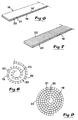
- a starting workpiece 18 which comprises two semi-stiff, although flexible bands 19, 19' which are held together and apart from each other by means of a plurality of interspaced interflanges 20. These interflanges are made in one piece with the two bands 19, 19' in order to delimit, by pairs and together with the bands, consecutive cavities or ducts 21 along the bands.
- the workpiece 18 that is made of one piece consists of comparatively thin plastic with a certain inherent stiffness.
- the thickness of the plastic may advantageously lie within the range of 0,2 to 0,8, suitably 0,4 to 0,6 mm.
- the internal distance between on one hand the bands 19, 19' and on the other hand adjacent interflanges 20, may advantageously lie within the range of 2 to 6, suitably about 3 to 4 mm.
- the ducts 21 advantageously have a square or rectangular cross-section with an area in the range of 4 to 36 mm 2 .
- the width of bands 19, 19' may be within the range of 20 to 70, suitably 20 to 50 mm, while their length varies depending upon the factual diameter of the air flow duct in question through the filter tube or the particle separating housing.
- the workpiece 18 as shown in fig. 6 is commercially available, albeit in units of a considerably larger length and width than shown in the figure.
- slots 22 are provided in one of the two bands 19, 19', in this case band 19', between adjacent interflanges 20.
- these slots are made between all pairs of adjacent interflanges, the individual slot suitably being located half-way between the flanges, extending parallel to these.
- the slots may be provided in different ways, e.g. by cutting with a suitable cutting tool. It is also feasible to make the slots already in connection with the production of the unit 18.
- the unit may be formed into a loop, preferably a spiral-shaped loop as shown in fig. 8, in that the slots permit bending the unit around the slot-free band part 19, the latter serving as a joining element.
- the band unit When the band unit is formed into a spiral according to fig. 8, the two bands 19, 19' will be located closely adjacently, whereby, however, the slotted band 19' will have obtained the shape of a plurality of lamella-like parts 23 which are internally separated in that the slots 22 widen in connection with the formation of the spiral loop. Thereby, the railhead-like lamella parts 23 form a support or abutment towards the inside of each externally located band part 19.
- a plastic foil 24 see fig.
- a strip-shaped plastic foil part 24, from which a plurality of strips 4 extend may be fastened to the band 19 without any high demands for, e.g., a glue joint or another joining means, for instance tape.
- a plastic foil is fastened precisely by gluing or with tape, but it is even feasible to keep the foil between on one hand the inside of band 19 and on the other hand the outside of the lamellae 23 merely by a squeezing effect.
- the unit formed into a spiral according to fig. 8 may in an advantageous way be used as a carrier 3 for strips 4. This is illustrated in fig. 10. However, it is also possible to use the spiral unit as a silencer of the kind indicated at 17 in fig. 5. In this case, the unit lacks strips.
- the band loop may, when the unit is used for silencing purposes, be wound into a spiral form (see fig. 10) at the same time as adjacent interflanges 20 are axially dislocated relative to each other to confer to the bands 19, 19', which are spiral-shaped when observed cross-sectionally, a helical shape when observed in the axial extension of the carrier. In this way, the capability of the unit or the insert to silence sounds in different frequency ranges is markedly increased. Such a helical shape can be conferred to the unit also in the case when it carries strips in the previously described way.
- the carrier may be formed in another way. It is for instance feasible to use a grate or a grate-like construction for holding the strips. Further, also other components than just strips may be used as movable, electricity-generating elements, for instance threads or thread-like elements. As electricity-generating elements, it is even feasible to use granule-shaped bodies of a suitable material, which are set in motion by the passing air. Such granule bodies can be held in place by the carrier together with, e.g., a grate cage or a perforated housing which is mounted within the filter tube in a suitable manner.
Landscapes
- Engineering & Computer Science (AREA)
- Chemical & Material Sciences (AREA)
- Combustion & Propulsion (AREA)
- Mechanical Engineering (AREA)
- General Engineering & Computer Science (AREA)
- Filtering Materials (AREA)
- Filtering Of Dispersed Particles In Gases (AREA)
- Combined Means For Separation Of Solids (AREA)
- Electrostatic Separation (AREA)
Applications Claiming Priority (3)
| Application Number | Priority Date | Filing Date | Title |
|---|---|---|---|
| SE9401947 | 1994-06-07 | ||
| SE9401947A SE502891C2 (sv) | 1994-06-07 | 1994-06-07 | Anordning för avskiljning av extremt fina partiklar ur luft |
| PCT/SE1995/000653 WO1995033569A1 (en) | 1994-06-07 | 1995-06-06 | A device for separating extremely fine particles from air |
Publications (2)
| Publication Number | Publication Date |
|---|---|
| EP0779839A1 EP0779839A1 (en) | 1997-06-25 |
| EP0779839B1 true EP0779839B1 (en) | 2000-07-26 |
Family
ID=20394256
Family Applications (1)
| Application Number | Title | Priority Date | Filing Date |
|---|---|---|---|
| EP95922055A Expired - Lifetime EP0779839B1 (en) | 1994-06-07 | 1995-06-06 | A device for separating extremely fine particles from air |
Country Status (9)
| Country | Link |
|---|---|
| US (1) | US5716431A (es) |
| EP (1) | EP0779839B1 (es) |
| AT (1) | ATE194928T1 (es) |
| AU (1) | AU2687795A (es) |
| DE (1) | DE69518158T2 (es) |
| DK (1) | DK0779839T3 (es) |
| ES (1) | ES2149366T3 (es) |
| SE (1) | SE502891C2 (es) |
| WO (1) | WO1995033569A1 (es) |
Families Citing this family (16)
| Publication number | Priority date | Publication date | Assignee | Title |
|---|---|---|---|---|
| SE511329C2 (sv) * | 1997-08-06 | 1999-09-13 | Eurus Airtech Ab | Anordning för rening av luft |
| SE512357C2 (sv) * | 1998-07-23 | 2000-03-06 | Freshman Ab | Luftreningsfilter samt förfarande för dess tillverkning |
| SE515487C2 (sv) * | 1999-12-06 | 2001-08-13 | Freshman Flimmer Ab | Förfarande och anläggning för tillverkning av luftreningsfilter samt filter tillverkat enligt förfarandet |
| US6654664B1 (en) | 2000-06-14 | 2003-11-25 | Multisen Technology, Inc. | Multimedia and scent storage medium and playback apparatus |
| US6602475B1 (en) | 2000-06-14 | 2003-08-05 | Multisen Technology, Inc. | Multimedia and scent storage medium and playback apparatus having electrostatic scent release |
| US6556272B1 (en) | 2000-06-14 | 2003-04-29 | Multisen Technology, Inc. | Multimedia and scent storage medium and playback apparatus |
| SE517368C2 (sv) * | 2000-10-19 | 2002-06-04 | Freshman Flimmer Ab | Luftreningsfilter med mjuka trådar av ett elektrostatiskt laddningsbart material |
| US20020114744A1 (en) * | 2000-11-16 | 2002-08-22 | Dah-Shiarn Chiao | Multimedia and scent storage cartridge design having electrostatic scent release and methods for using same |
| DE20312288U1 (de) * | 2003-08-08 | 2003-12-11 | Trw Occupant Restraint Systems Gmbh & Co. Kg | Gurtaufroller mit Sperrmechanismus |
| JP5087558B2 (ja) * | 2006-01-13 | 2012-12-05 | ゼンダー グループ ノルディック エー ビー | エアフィルタおよびかかるエアフィルタの製造方法 |
| SE530041C2 (sv) * | 2006-07-14 | 2008-02-12 | Freshman Ab | Luftfilterarrangemang och ett förfarande för tillverkning av ett sådant luftfilterarrangemang |
| NL2001650C2 (nl) * | 2008-06-05 | 2009-12-08 | Blue Temple B V | Filterinrichting en filter voor toepassing daarin alsmede een afscheidingsscherm voor plaatsing langs een verkeersweg. |
| US8608838B2 (en) * | 2010-01-22 | 2013-12-17 | Yau Lee Innovative Technology, Ltd. | Tubing air purification system |
| CN103331210B (zh) * | 2011-01-21 | 2015-12-02 | 有利创新科技有限公司 | 管式空气净化系统 |
| WO2025197816A1 (ja) * | 2024-03-21 | 2025-09-25 | 株式会社村田製作所 | 吸着フィルタ |
| WO2026022084A1 (en) * | 2024-07-23 | 2026-01-29 | Zehnder Group International Ag | Air filtering device for filtering of air and method of maintaining an air filtering device |
Family Cites Families (10)
| Publication number | Priority date | Publication date | Assignee | Title |
|---|---|---|---|---|
| US2657339A (en) * | 1953-10-27 | Method and apparatus for producing | ||
| US2277712A (en) * | 1939-02-04 | 1942-03-31 | Slayter Electronic Corp | Electric discharge electrode |
| US2593869A (en) * | 1948-07-15 | 1952-04-22 | Fruth Hal Frederick | Air purification device |
| US2973830A (en) * | 1958-10-16 | 1961-03-07 | Purolator Products Inc | Air cleaning means |
| US3616604A (en) * | 1968-01-02 | 1971-11-02 | Tri Mer Corp | Liquid recovery apparatus |
| US3744216A (en) * | 1970-08-07 | 1973-07-10 | Environmental Technology | Air purifier |
| IT942698B (it) * | 1970-11-28 | 1973-04-02 | Buderus Eisenwerk | Filtro elettrostatico per aria ed altri gas |
| SU1125053A1 (ru) * | 1982-11-29 | 1984-11-23 | Институт Физико-Органической Химии И Углехимии Ордена Ленина Ан Усср | Устройство дл электризации пылевого аэрозол |
| BR8406886A (pt) * | 1983-05-10 | 1985-04-16 | Soederhamn Ind Arbetshygien Ab | Dispositivo de filtracao para purificacao de ar ou gas |
| ZA935518B (en) * | 1992-07-30 | 1994-02-24 | E V E Holdings Limited | Improved filter |
-
1994
- 1994-06-07 SE SE9401947A patent/SE502891C2/sv not_active IP Right Cessation
-
1995
- 1995-06-06 ES ES95922055T patent/ES2149366T3/es not_active Expired - Lifetime
- 1995-06-06 AT AT95922055T patent/ATE194928T1/de not_active IP Right Cessation
- 1995-06-06 US US08/750,455 patent/US5716431A/en not_active Expired - Fee Related
- 1995-06-06 EP EP95922055A patent/EP0779839B1/en not_active Expired - Lifetime
- 1995-06-06 DK DK95922055T patent/DK0779839T3/da active
- 1995-06-06 WO PCT/SE1995/000653 patent/WO1995033569A1/en not_active Ceased
- 1995-06-06 DE DE69518158T patent/DE69518158T2/de not_active Expired - Fee Related
- 1995-06-06 AU AU26877/95A patent/AU2687795A/en not_active Abandoned
Also Published As
| Publication number | Publication date |
|---|---|
| WO1995033569A1 (en) | 1995-12-14 |
| DK0779839T3 (da) | 2000-11-13 |
| SE9401947L (sv) | 1995-12-08 |
| ES2149366T3 (es) | 2000-11-01 |
| ATE194928T1 (de) | 2000-08-15 |
| EP0779839A1 (en) | 1997-06-25 |
| DE69518158D1 (de) | 2000-08-31 |
| US5716431A (en) | 1998-02-10 |
| SE9401947D0 (sv) | 1994-06-07 |
| DE69518158T2 (de) | 2001-03-22 |
| SE502891C2 (sv) | 1996-02-12 |
| AU2687795A (en) | 1996-01-04 |
Similar Documents
| Publication | Publication Date | Title |
|---|---|---|
| EP0779839B1 (en) | A device for separating extremely fine particles from air | |
| EP0703827B1 (en) | Device for the separation of microscopic particules out of air | |
| US5330559A (en) | Method and apparatus for electrostatically cleaning particulates from air | |
| US4662903A (en) | Electrostatic dust collector | |
| US4147522A (en) | Electrostatic dust collector | |
| US8252095B2 (en) | Filter media for active field polarized media air cleaner | |
| US6096118A (en) | Electrostatic separator for separating solid particles from a gas stream | |
| US6790259B2 (en) | Method and device for cleaning a gaseous fluid using a conductive grid between charging head and filter | |
| US4354858A (en) | Method for filtering particulates | |
| US4904283A (en) | Enhanced fabric filtration through controlled electrostatically augmented dust deposition | |
| EP1596960B1 (en) | Air cleanness filter | |
| US4976749A (en) | Air filter and particle removal system | |
| US3489669A (en) | Electrohydrodynamic apparatus for removing particles from a particle-laden fluid | |
| WO1999003590A1 (en) | Induced voltage electrode filter system with disposable cartridge | |
| EP0626886A1 (en) | ELECTROSTATIC TWO-STAGE FILTER. | |
| US9764331B2 (en) | Filter media for active field polarized media air cleaner | |
| US6758884B2 (en) | Air filtration system using point ionization sources | |
| US7141098B2 (en) | Air filtration system using point ionization sources | |
| AU2006200463B8 (en) | Apparatus and method for the removal of particulate matter in a filtration system | |
| CA3056313A1 (en) | Corrugated filtration media for polarizing air cleaner | |
| US3768233A (en) | Filter construction | |
| US9808808B2 (en) | Electrostatic precipitator | |
| EP0248925B1 (en) | Electrostatic dust collector | |
| RU2106106C1 (ru) | Пылесос и фильтр для пылесоса | |
| JPS6287262A (ja) | 空気清浄装置 |
Legal Events
| Date | Code | Title | Description |
|---|---|---|---|
| PUAI | Public reference made under article 153(3) epc to a published international application that has entered the european phase |
Free format text: ORIGINAL CODE: 0009012 |
|
| 17P | Request for examination filed |
Effective date: 19970305 |
|
| AK | Designated contracting states |
Kind code of ref document: A1 Designated state(s): AT BE CH DE DK ES FR GB IT LI NL |
|
| 17Q | First examination report despatched |
Effective date: 19990610 |
|
| GRAG | Despatch of communication of intention to grant |
Free format text: ORIGINAL CODE: EPIDOS AGRA |
|
| GRAG | Despatch of communication of intention to grant |
Free format text: ORIGINAL CODE: EPIDOS AGRA |
|
| GRAH | Despatch of communication of intention to grant a patent |
Free format text: ORIGINAL CODE: EPIDOS IGRA |
|
| GRAH | Despatch of communication of intention to grant a patent |
Free format text: ORIGINAL CODE: EPIDOS IGRA |
|
| GRAA | (expected) grant |
Free format text: ORIGINAL CODE: 0009210 |
|
| AK | Designated contracting states |
Kind code of ref document: B1 Designated state(s): AT BE CH DE DK ES FR GB IT LI NL |
|
| REF | Corresponds to: |
Ref document number: 194928 Country of ref document: AT Date of ref document: 20000815 Kind code of ref document: T |
|
| ITF | It: translation for a ep patent filed | ||
| REG | Reference to a national code |
Ref country code: CH Ref legal event code: NV Representative=s name: BOVARD AG PATENTANWAELTE Ref country code: CH Ref legal event code: EP |
|
| REF | Corresponds to: |
Ref document number: 69518158 Country of ref document: DE Date of ref document: 20000831 |
|
| ET | Fr: translation filed | ||
| REG | Reference to a national code |
Ref country code: ES Ref legal event code: FG2A Ref document number: 2149366 Country of ref document: ES Kind code of ref document: T3 |
|
| REG | Reference to a national code |
Ref country code: DK Ref legal event code: T3 |
|
| PGFP | Annual fee paid to national office [announced via postgrant information from national office to epo] |
Ref country code: GB Payment date: 20010518 Year of fee payment: 7 |
|
| PGFP | Annual fee paid to national office [announced via postgrant information from national office to epo] |
Ref country code: ES Payment date: 20010523 Year of fee payment: 7 |
|
| PGFP | Annual fee paid to national office [announced via postgrant information from national office to epo] |
Ref country code: AT Payment date: 20010529 Year of fee payment: 7 |
|
| PGFP | Annual fee paid to national office [announced via postgrant information from national office to epo] |
Ref country code: FR Payment date: 20010530 Year of fee payment: 7 |
|
| PLBE | No opposition filed within time limit |
Free format text: ORIGINAL CODE: 0009261 |
|
| STAA | Information on the status of an ep patent application or granted ep patent |
Free format text: STATUS: NO OPPOSITION FILED WITHIN TIME LIMIT |
|
| PGFP | Annual fee paid to national office [announced via postgrant information from national office to epo] |
Ref country code: CH Payment date: 20010612 Year of fee payment: 7 |
|
| PGFP | Annual fee paid to national office [announced via postgrant information from national office to epo] |
Ref country code: BE Payment date: 20010622 Year of fee payment: 7 |
|
| PGFP | Annual fee paid to national office [announced via postgrant information from national office to epo] |
Ref country code: DK Payment date: 20010625 Year of fee payment: 7 |
|
| PGFP | Annual fee paid to national office [announced via postgrant information from national office to epo] |
Ref country code: NL Payment date: 20010630 Year of fee payment: 7 |
|
| 26N | No opposition filed | ||
| PGFP | Annual fee paid to national office [announced via postgrant information from national office to epo] |
Ref country code: DE Payment date: 20010827 Year of fee payment: 7 |
|
| REG | Reference to a national code |
Ref country code: GB Ref legal event code: IF02 |
|
| PG25 | Lapsed in a contracting state [announced via postgrant information from national office to epo] |
Ref country code: GB Free format text: LAPSE BECAUSE OF NON-PAYMENT OF DUE FEES Effective date: 20020606 Ref country code: AT Free format text: LAPSE BECAUSE OF NON-PAYMENT OF DUE FEES Effective date: 20020606 |
|
| PG25 | Lapsed in a contracting state [announced via postgrant information from national office to epo] |
Ref country code: ES Free format text: LAPSE BECAUSE OF NON-PAYMENT OF DUE FEES Effective date: 20020607 |
|
| PG25 | Lapsed in a contracting state [announced via postgrant information from national office to epo] |
Ref country code: LI Free format text: LAPSE BECAUSE OF NON-PAYMENT OF DUE FEES Effective date: 20020630 Ref country code: CH Free format text: LAPSE BECAUSE OF NON-PAYMENT OF DUE FEES Effective date: 20020630 Ref country code: BE Free format text: LAPSE BECAUSE OF NON-PAYMENT OF DUE FEES Effective date: 20020630 |
|
| PG25 | Lapsed in a contracting state [announced via postgrant information from national office to epo] |
Ref country code: DK Free format text: LAPSE BECAUSE OF NON-PAYMENT OF DUE FEES Effective date: 20020731 |
|
| BERE | Be: lapsed |
Owner name: *FRESHMAN A.B. Effective date: 20020630 |
|
| PG25 | Lapsed in a contracting state [announced via postgrant information from national office to epo] |
Ref country code: NL Free format text: LAPSE BECAUSE OF NON-PAYMENT OF DUE FEES Effective date: 20030101 Ref country code: DE Free format text: LAPSE BECAUSE OF NON-PAYMENT OF DUE FEES Effective date: 20030101 |
|
| GBPC | Gb: european patent ceased through non-payment of renewal fee |
Effective date: 20020606 |
|
| REG | Reference to a national code |
Ref country code: DK Ref legal event code: EBP |
|
| REG | Reference to a national code |
Ref country code: CH Ref legal event code: PL |
|
| PG25 | Lapsed in a contracting state [announced via postgrant information from national office to epo] |
Ref country code: FR Free format text: LAPSE BECAUSE OF NON-PAYMENT OF DUE FEES Effective date: 20030228 |
|
| NLV4 | Nl: lapsed or anulled due to non-payment of the annual fee |
Effective date: 20030101 |
|
| REG | Reference to a national code |
Ref country code: FR Ref legal event code: ST |
|
| REG | Reference to a national code |
Ref country code: ES Ref legal event code: FD2A Effective date: 20030711 |
|
| PG25 | Lapsed in a contracting state [announced via postgrant information from national office to epo] |
Ref country code: IT Free format text: LAPSE BECAUSE OF NON-PAYMENT OF DUE FEES;WARNING: LAPSES OF ITALIAN PATENTS WITH EFFECTIVE DATE BEFORE 2007 MAY HAVE OCCURRED AT ANY TIME BEFORE 2007. THE CORRECT EFFECTIVE DATE MAY BE DIFFERENT FROM THE ONE RECORDED. Effective date: 20050606 |