EP0779477B1 - Ausdehnungsgefäss - Google Patents
Ausdehnungsgefäss Download PDFInfo
- Publication number
- EP0779477B1 EP0779477B1 EP96203476A EP96203476A EP0779477B1 EP 0779477 B1 EP0779477 B1 EP 0779477B1 EP 96203476 A EP96203476 A EP 96203476A EP 96203476 A EP96203476 A EP 96203476A EP 0779477 B1 EP0779477 B1 EP 0779477B1
- Authority
- EP
- European Patent Office
- Prior art keywords
- conduit
- expansion vessel
- inner part
- bush
- vessel according
- Prior art date
- Legal status (The legal status is an assumption and is not a legal conclusion. Google has not performed a legal analysis and makes no representation as to the accuracy of the status listed.)
- Expired - Lifetime
Links
- 210000002445 nipple Anatomy 0.000 claims abstract description 24
- 239000007788 liquid Substances 0.000 claims abstract description 22
- 239000012528 membrane Substances 0.000 abstract description 11
- XLYOFNOQVPJJNP-UHFFFAOYSA-N water Substances O XLYOFNOQVPJJNP-UHFFFAOYSA-N 0.000 description 23
- 238000010438 heat treatment Methods 0.000 description 9
- 239000008399 tap water Substances 0.000 description 7
- 235000020679 tap water Nutrition 0.000 description 7
- 230000000284 resting effect Effects 0.000 description 2
- 230000004308 accommodation Effects 0.000 description 1
Images



Classifications
-
- F—MECHANICAL ENGINEERING; LIGHTING; HEATING; WEAPONS; BLASTING
- F24—HEATING; RANGES; VENTILATING
- F24D—DOMESTIC- OR SPACE-HEATING SYSTEMS, e.g. CENTRAL HEATING SYSTEMS; DOMESTIC HOT-WATER SUPPLY SYSTEMS; ELEMENTS OR COMPONENTS THEREFOR
- F24D3/00—Hot-water central heating systems
- F24D3/10—Feed-line arrangements, e.g. providing for heat-accumulator tanks, expansion tanks ; Hydraulic components of a central heating system
- F24D3/1008—Feed-line arrangements, e.g. providing for heat-accumulator tanks, expansion tanks ; Hydraulic components of a central heating system expansion tanks
- F24D3/1016—Tanks having a bladder
-
- F—MECHANICAL ENGINEERING; LIGHTING; HEATING; WEAPONS; BLASTING
- F24—HEATING; RANGES; VENTILATING
- F24D—DOMESTIC- OR SPACE-HEATING SYSTEMS, e.g. CENTRAL HEATING SYSTEMS; DOMESTIC HOT-WATER SUPPLY SYSTEMS; ELEMENTS OR COMPONENTS THEREFOR
- F24D3/00—Hot-water central heating systems
- F24D3/10—Feed-line arrangements, e.g. providing for heat-accumulator tanks, expansion tanks ; Hydraulic components of a central heating system
- F24D3/1008—Feed-line arrangements, e.g. providing for heat-accumulator tanks, expansion tanks ; Hydraulic components of a central heating system expansion tanks
-
- F—MECHANICAL ENGINEERING; LIGHTING; HEATING; WEAPONS; BLASTING
- F24—HEATING; RANGES; VENTILATING
- F24D—DOMESTIC- OR SPACE-HEATING SYSTEMS, e.g. CENTRAL HEATING SYSTEMS; DOMESTIC HOT-WATER SUPPLY SYSTEMS; ELEMENTS OR COMPONENTS THEREFOR
- F24D3/00—Hot-water central heating systems
- F24D3/10—Feed-line arrangements, e.g. providing for heat-accumulator tanks, expansion tanks ; Hydraulic components of a central heating system
- F24D3/1008—Feed-line arrangements, e.g. providing for heat-accumulator tanks, expansion tanks ; Hydraulic components of a central heating system expansion tanks
- F24D3/1041—Flow-through
Definitions
- the invention relates to an expansion vessel according to the preamble of claim 1.
- Such an expansion vessel is known from EP-A-0 602 430.
- the known expansion vessel is used in open pipe systems with a heating unit, for example for tap water for the kitchen or shower, in which the expansion vessel takes care of the change in volume of the water which is the result of the water being heated by the heating unit.
- the known expansion vessel has the drawback that one of the first and second conduits is formed by a pipe extending axially into the expansion vessel, almost over the entire height thereof. This pipe limits the movements of the dividing means in the form of a balloon-shaped membrane and may damage this membrane.
- the object of the invention is to provide an expansion vessel of the abovementioned type, of which the liquid chamber can be completely flown-through but which does not have the abovementioned drawback.
- the first conduit and the second conduit debouche at a relatively large distance from each other so that the through-flow through the liquid chamber is excellent and no areas with stagnant water can occur.
- the shape of the inner part of the through-flow means is such that the membrane will not be damaged.
- Fig. 1 shows a preferred embodiment of the expansion vessel according to the invention, comprising a housing formed by two parts, a top part 1 with a connecting nipple 3, by means of which the expansion vessel can be connected to a pipe system, and a bottom part 2 with a gas filling aperture 4, and a dividing means formed by a membrane 6 which is clamped between the top part 1 and the bottom part 2 by means of a clamping ring 5.
- the expansion vessel according to the invention also comprises a through-flow means 9a, which is fitted at the position of the connecting nipple 3.
- Said through-flow means 9a has two conduits 10 and 11, of which one conduit, depending on the direction of flow of the medium in the pipe system, is the inflow conduit, while the other conduit is the outflow conduit.
- a connecting piece 12 is fitted on the connecting nipple 3.
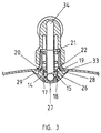
- Figs. 2 and 3 show the connecting part of the expansion vessel of Fig. 1 on an enlarged scale.
- the connecting piece 12 has two conduits 34, 35, which connect to the conduit 10 and the conduit 11 of the through-flow means 9a.
- the through-flow means 9a is composed essentially of two parts, a bush 13 and an inner part 7.
- the bush 13 is inserted through the connecting nipple 3, and on the inside of the expansion vessel is inserted into an aperture 16 of the inner part 7.
- the bush 13 and the inner part 7 are immovably connected to each other.
- the bush 13 has two projections 14, 15 which are elastically movable in a plane through the axis of the bush.
- the inner part 7 has two recesses 17, 18 which correspond to the movable projections 14, 15.
- the movable projections 14, 15 hook behind edges 19, 20 in the recesses 17, 18.
- the bush 13 is essentially cylindrical and has at one end a flanged edge 21 with apertures. At the other end, the end face of the bush 13 is closed, and an aperture 22 is provided on the periphery of the bush 13.
- the axis of the aperture 22 is at right angles to the plane of the movable projections 14, 15. Diametrically opposite the aperture 22, the bush 13 has a wall 36.
- the inner part 7 is composed of two parts (see Fig. 4): a main part 26, which rests against the inside of the top part 1 of the housing, and a wall part 27. These parts can be mass-produced in self-releasing moulds and are expediently made of plastic.
- the main part 26 and the wall part 27 are connected to each other by means of a snap closure.
- Said snap closure extends in the lengthwise direction on the outside of the wall part 27 and on the inside of the main part 26.
- the main part 26 has two wings 28, 29 extending in the lengthwise direction, and preferably in the centre has the aperture 16 with the recesses 17, 18 for the accommodation of the projections 14, 15 of the bush 13.
- the main part 26 has two ends 31, 32, which in the preferred embodiment are scoop-shaped and have apertures through which a medium can flow.
- Assembling the main part 26 and the wall part 27 produces the inner part 7, in which a conduit extending in the lengthwise direction is formed.
- the contour of the inner part 7 along the wings 28, 29 and the scoop-shaped ends 31, 32 connects accurately to the inside of the top part 1 of the housing, with the result that a conduit 33 is formed between the inner part 7 and the top part 1 of the housing (see Fig. 3).
- the through-flow means 9a is assembled by inserting the bush 13 through the connecting nipple 3 and into the aperture 16 of the inner part 7.
- the wall 36 divides the conduit of the inner part 7, extending in the lengthwise direction, into two parts.
- the movable projections 14, 15 also serve as positioning lugs, in order to ensure that the connecting conduit 25 in the connecting nipple 3 opens out by way of aperture 22 in the bush 13 into a part of the conduit of the inner part 7 extending in the lengthwise direction, so that the conduit 11 is formed.
- the fact that the bush 13 with the end inserted into the aperture 16 has a wall 36 means that a connection is produced between the other part of the conduit of the inner part 7 extending in the lengthwise direction and the connecting conduit 24 formed between the bush 13 and the connecting nipple 3, so that the conduit 10 is formed.
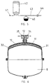
- Fig. 5 shows diagrammatically a tap water pipe system with a supply pipe 43, to which an expansion vessel according to the invention, indicated by 40, is connected.
- the water is heated up by means of a heating unit 42. Hot water can be drawn from a tap 41.
- a non-return valve 44 is incorporated in the supply pipe.
- the water flows from the heating unit 42 to the expansion vessel 40, since the non-return valve 44 prevents return flow into the supply pipe 43.
- the state of the expansion vessel is then as shown in Fig. 1.
- the water flows by way of the conduit 35 of the connecting piece 12 through the conduit 10 - which is acting as an inflow conduit - of the through-flow means 9a into the liquid chamber 9 of the expansion vessel.
- the water here flows through the apertures in the scoop-shaped end 32. Said apertures are positioned in such a way that the water flows into the liquid chamber 9 in different directions.
- the change in volume of the water is taken care of by movement of the membrane 6, in which case the gas in the gas chamber 8 is compressed until the pressure in the gas chamber 8 is equal to the pressure in the tap water pipe system.
- the pressure in the tap water pipe system drops quickly. This pressure is lower than the pressure in the gas chamber 8 of the expansion vessel 40.
- the water in the expansion vessel 40 is consequently forced by way of the conduit 10 - which is now acting as an outflow conduit - and conduit 35 of the connecting piece 12 to the heating unit 42.
- Water also flows from the supply pipe 43 by way of the conduit 34 of the connecting piece 12 through the conduit 11 - which is now acting as an inflow conduit - to the scoop-shaped end 31. From there, the water flows by way of the apertures in the scoop-shaped end 31 into the liquid chamber 9.
- the apertures are positioned in such a way that the water flows into the liquid chamber 9 in different directions.
- the water then flows from the liquid chamber 9 by way of the apertures in the scoop-shaped end 32, the conduit 10 and the conduit 35 to the heating unit 42. Consequently the liquid chamber 9 is completely flown through and no areas with stagnant water occur. Some of the water flowing in from the supply pipe 43 will flow from the scoop-shaped end 31, by way of the conduit 33 formed between the inner part 7 and the inside of the top part 1 of the housing, to the scoop-shaped end 32.
- the tap 41 When the tap 41 is opened and the pressure in the tap water pipe system drops so low that the membrane 6 rests against the inner part 7 and the inside wall of the top part 1 of the housing (a situation which is shown in Fig. 6), the apertures in the scoop-shaped end 31 are shut off by the membrane 6 resting against the inner part 7.
- the water then flows only by way of the conduit 33 to the scoop-shaped end 32 and by way of the conduit 10 and the conduit 35 of the connecting piece 12 to the heating unit 42.
- the expansion vessel is completely flown through.
- the shape of the inner part 7 is such that when the membrane 6 rests against the inner part 7 and the inside of the top part 1 it forms no angles which are smaller than preferably 120°.
- Expansion vessels with other dividing means - such as, for example, a piston - for separating a gas chamber and a liquid chamber can also be improved by fitting a through-flow means according to the invention in the expansion vessel.
Landscapes
- Engineering & Computer Science (AREA)
- General Engineering & Computer Science (AREA)
- Chemical & Material Sciences (AREA)
- Thermal Sciences (AREA)
- Combustion & Propulsion (AREA)
- Mechanical Engineering (AREA)
- Physics & Mathematics (AREA)
- Analysing Materials By The Use Of Radiation (AREA)
- Glass Compositions (AREA)
- Table Devices Or Equipment (AREA)
- Quick-Acting Or Multi-Walled Pipe Joints (AREA)
- Cookers (AREA)
- Indicating Or Recording The Presence, Absence, Or Direction Of Movement (AREA)
Claims (12)
- Ausdehnungsgefäß mit einer Flüssigkeitskammer (9) und einer Gaskammer (8), wobei die betreffenden Kammern durch eine Trenneinrichtung (6) voneinander getrennt sind,
wobei das Ausdehnungsgefäß einen Anschlußstutzen (3) aufweist, durch den die Flüssigkeitskammer (9) mit einem Rohrleitungssystem verbunden werden kann, und wobei in der Position des Anschlußstutzens (3) eine Durchflußeinrichtung (9a) in dem Ausdehnungsgefäß angebracht ist, die zumindest eine erste Rohrleitung (10) und zumindest eine zweite Rohrleitung (11) aufweist, die von der ersten Rohrleitung im wesentlichen getrennt ist,
wobei die erste Rohrleitung (10) und die zweite Rohrleitung (11) in der Flüssigkeitskammer (9) des Ausdehnungsgefäßes in einem Abstand voneinander offen sind,
dadurch gekennzeichnet, dass die erste Rohrleitung (10) und die zweite Rohrleitung (11) beide durch ein längliches inneres Teil (7) der Durchflußeinrichtung (9a) gebildet sind, das sich diametral in der Flüssigkeitskammer (9) erstreckt,
und dass die erste Rohrleitung (10) und die zweite Rohrleitung (11) sich von einem mittleren Bereich des inneren Teiles (7), der nahe des Anschlußstutzens (3) angeordnet ist, zu den Enden des inneren Teiles (7) in diametral gegenüberliegenden Richtungen erstrecken. - Ausdehnungsgefäß nach Anspruch 1, dadurch gekennzeichnet, dass der innere Teil (7) der Durchflußeinrichtung (9a) zumindest eine dritte Rohrleitung (33) bildet, welche die Enden der ersten Rohrleitung (10) und der zweiten Rohrleitung (11) direkt miteinander verbindet.
- Ausdehnungsgefäß nach Anspruch 1 oder 2, dadurch gekennzeichnet, dass die erste Rohrleitung (10) und die zweite Rohrleitung (11) jeweils über mehrere Öffnungen in der Durchflußeinrichtung (9a) zu der Flüssigkeitskammer (9) hin offen sind.
- Ausdehnungsgefäß nach den Ansprüchen 1 bis 3,
dadurch gekennzeichnet, dass die Durchflußeinrichtung (9a) im wesentlichen aus zwei gesonderten Teilen besteht, einer Büchse (13), die durch den Anschlußstutzen (3) ragt, und dem inneren Teil (7), der mit der Büchse (13) verbunden ist. - Ausdehnungsgefäß nach Anspruch 4, dadurch gekennzeichnet, dass die Büchse ((13) in dem Anschlußstutzen (3) eine erste Verbindungsrohrleitung (24) und eine zweite Verbindungsrohrleitung (25) bildet.
- Ausdehnungsgefäß nach Anspruch 4 oder 5, dadurch gekennzeichnet, dass der innere Teil (7) eine Rohrleitung aufweist, die durch die Büchse (13) in zwei Rohrleitungsteile aufgeteilt ist, welche voneinander getrennt sind und welche die erste Rohrleitung (10) und die zweite Rohrleitung (11) der Durchflußeinrichtung (9a) bilden, dass der eine Rohrleitungsteil mit der ersten Verbindungsrohrleitung (24) in dem Anschlußstutzen (3) verbunden ist und dass der andere Rohrleitungsteil mit der zweiten Verbindungsrohrleitung (25) in dem Anschlußstutzen (3) verbunden ist.
- Ausdehnungsgefäß nach einem der Ansprüche 4 bis 6,
dadurch gekennzeichnet, dass die erste Verbindungsrohrleitung (24), die durch die Büchse (13) in dem Verbindungsstutzen (3) gebildet ist, im wesentlichen konzentrisch zu der zweiten Verbindungsrohrleitung (25) vorgesehen ist, die durch die Büchse (13) in dem Anschlußstutzen (3) gebildet ist. - Ausdehnungsgefäß nach einem der Ansprüche 4 bis 7,
dadurch gekennzeichnet, dass die Büchse (13) in eine Öffnung (16) in dem inneren Teil (7) hineinragt und in einer Ebene durch ihre Achse mit bewegbaren Vorsprüngen (14, 15) versehen ist, die in entsprechende Ausnehmungen (17, 18) passen, welche in der Öffnung (16) in dem inneren Teil (7) gebildet sind,
und dass Einrichtungen vorgesehen sind, durch die die Büchse (13) an dem inneren Teil (7) der Durchflußeinrichtung (9a) befestigt ist. - Ausdehnungsgefäß nach einem der Ansprüche 1 bis 8,
dadurch gekennzeichnet, dass der innere Teil (7) aus zwei Teilen (26, 27) besteht, deren jedes ein Teil der Wand der Rohrleitung in dem inneren Teil (7) bildet und die mittels einer Schnappverbindung miteinander verbunden sind, welche sich in Längsrichtung des inneren Teiles (7) erstreckt. - Ausdehnungsgefäß nach einem der Ansprüche 1 bis 9,
dadurch gekennzeichnet, dass ein Anschlußstück (12) an dem Anschlußstutzen (3) angebracht ist für den Anschluß des Ausdehnungsgefäßes an ein Rohrleitungssystem. - Ausdehnungsgefäß nach Anspruch 10, dadurch gekennzeichnet, dass das Anschlußstück (12) in der Innenseite zwei Rohrleitungen (34, 35) aufweist, die voneinander getrennt sind und die jeweils mit einer durch die Büchse (13) in dem Anschlußstutzen (3) des Ausdehnungsgefäßes gebildeten Verbindungsrohrleitung (24, 25) verbunden sind.
- Ausdehnungsgefäß nach Anspruch 10 oder 11,
dadurch gekennzeichnet, dass das Anschlußstück (12) in Form eines T-Stückes vorliegt.
Applications Claiming Priority (2)
| Application Number | Priority Date | Filing Date | Title |
|---|---|---|---|
| NL1001915A NL1001915C2 (nl) | 1995-12-15 | 1995-12-15 | Expansievat. |
| NL1001915 | 1995-12-15 |
Publications (2)
| Publication Number | Publication Date |
|---|---|
| EP0779477A1 EP0779477A1 (de) | 1997-06-18 |
| EP0779477B1 true EP0779477B1 (de) | 2002-03-27 |
Family
ID=19762047
Family Applications (1)
| Application Number | Title | Priority Date | Filing Date |
|---|---|---|---|
| EP96203476A Expired - Lifetime EP0779477B1 (de) | 1995-12-15 | 1996-12-09 | Ausdehnungsgefäss |
Country Status (4)
| Country | Link |
|---|---|
| EP (1) | EP0779477B1 (de) |
| AT (1) | ATE215207T1 (de) |
| DE (1) | DE69620115T2 (de) |
| NL (1) | NL1001915C2 (de) |
Families Citing this family (4)
| Publication number | Priority date | Publication date | Assignee | Title |
|---|---|---|---|---|
| NL1010978C2 (nl) | 1999-01-07 | 2000-07-11 | Flamco Bv | Stromingsverdeler. |
| EP3048374A1 (de) | 2015-01-22 | 2016-07-27 | Global Water Solutions Ltd. | NACHRÜSTBARE DURCHLAUFVERBINDERANORDNUNG UND AUSDEHNUNGSGEFÄßVORRICHTUNG |
| IT201600125230A1 (it) * | 2016-12-12 | 2018-06-12 | Zilmet S P A | Raccordo migliorato per vasi di espansione |
| CN111121132B (zh) * | 2018-10-30 | 2021-10-01 | 宁波方太厨具有限公司 | 膨胀水箱自动充气结构及其控制方法 |
Family Cites Families (3)
| Publication number | Priority date | Publication date | Assignee | Title |
|---|---|---|---|---|
| DE8507701U1 (de) * | 1985-03-15 | 1985-06-20 | Flamco B.V., Gouda | Ausdehnungsgefäss |
| DE8507703U1 (de) * | 1985-03-15 | 1985-08-01 | Flamco B.V., Gouda | Anschlußstück für ein Ausdehnungsgefäß |
| DE4242036B4 (de) * | 1992-12-12 | 2004-04-15 | Hans Sasserath & Co. Kg | Anschlußarmatur zum Anschließen eines Ausdehnungsgefäßes |
-
1995
- 1995-12-15 NL NL1001915A patent/NL1001915C2/nl not_active IP Right Cessation
-
1996
- 1996-12-09 AT AT96203476T patent/ATE215207T1/de not_active IP Right Cessation
- 1996-12-09 DE DE69620115T patent/DE69620115T2/de not_active Expired - Lifetime
- 1996-12-09 EP EP96203476A patent/EP0779477B1/de not_active Expired - Lifetime
Also Published As
| Publication number | Publication date |
|---|---|
| DE69620115D1 (de) | 2002-05-02 |
| EP0779477A1 (de) | 1997-06-18 |
| ATE215207T1 (de) | 2002-04-15 |
| NL1001915C2 (nl) | 1997-06-17 |
| DE69620115T2 (de) | 2002-11-07 |
Similar Documents
| Publication | Publication Date | Title |
|---|---|---|
| US7303091B2 (en) | Expansion tank with double diaphragm | |
| US3557827A (en) | Pressure vessel for water conditioner assembly | |
| US3662780A (en) | Fluid flow directing structure for pressure vessel | |
| US20030062087A1 (en) | Quick connect/disconnect water faucet conduit assembly | |
| US7322488B2 (en) | Expansion tank with double diaphragm | |
| PL179229B1 (pl) | Zawór dla czynników gazowych PL | |
| ATE79667T1 (de) | Warmwasserspeicher mit einem von brauchwasser durchstroemten heizkreis mit aussen liegendem heizelement und mit einer ladewechselvorrichtung. | |
| US9777857B2 (en) | Flow control valve | |
| EP0779477B1 (de) | Ausdehnungsgefäss | |
| GB2202320A (en) | Central heating radiator assembly | |
| US3726475A (en) | Back pressure valve for thermal compensating dip tube | |
| US20060001260A1 (en) | Fluid vortex manifold | |
| EP0592398A1 (de) | Gerät zur messung und steuerung von temperatur und/oder druck. | |
| CA2584183C (en) | Expansion tank with double diaphragm | |
| US3493010A (en) | Control valve for fluid dispensing system | |
| CS156591A3 (en) | Distributor for branching pipes through which at least one medium flows | |
| CN208535226U (zh) | 一种结构改进的龙头阀体 | |
| WO1991009248A1 (en) | Valve assemblies | |
| AU675601B2 (en) | Connection tubes | |
| US20240044517A1 (en) | Expansion assembly and hot water tank | |
| US20240044516A1 (en) | Compensation assembly and hot water storage tank | |
| HK1090411B (en) | Expansion tank with double diaphragm | |
| JPH0742859A (ja) | 水回路用減圧弁 | |
| CN208565661U (zh) | 一种智能安防恒温阀 | |
| JPS6350526Y2 (de) |
Legal Events
| Date | Code | Title | Description |
|---|---|---|---|
| PUAI | Public reference made under article 153(3) epc to a published international application that has entered the european phase |
Free format text: ORIGINAL CODE: 0009012 |
|
| AK | Designated contracting states |
Kind code of ref document: A1 Designated state(s): AT BE CH DE DK ES FI FR GB IE IT LI LU NL PT SE |
|
| 17P | Request for examination filed |
Effective date: 19971215 |
|
| 17Q | First examination report despatched |
Effective date: 19991104 |
|
| GRAG | Despatch of communication of intention to grant |
Free format text: ORIGINAL CODE: EPIDOS AGRA |
|
| GRAG | Despatch of communication of intention to grant |
Free format text: ORIGINAL CODE: EPIDOS AGRA |
|
| GRAH | Despatch of communication of intention to grant a patent |
Free format text: ORIGINAL CODE: EPIDOS IGRA |
|
| GRAH | Despatch of communication of intention to grant a patent |
Free format text: ORIGINAL CODE: EPIDOS IGRA |
|
| REG | Reference to a national code |
Ref country code: GB Ref legal event code: IF02 |
|
| GRAA | (expected) grant |
Free format text: ORIGINAL CODE: 0009210 |
|
| AK | Designated contracting states |
Kind code of ref document: B1 Designated state(s): AT BE CH DE DK ES FI FR GB IE IT LI LU NL PT SE |
|
| PG25 | Lapsed in a contracting state [announced via postgrant information from national office to epo] |
Ref country code: NL Free format text: LAPSE BECAUSE OF FAILURE TO SUBMIT A TRANSLATION OF THE DESCRIPTION OR TO PAY THE FEE WITHIN THE PRESCRIBED TIME-LIMIT Effective date: 20020327 Ref country code: LI Free format text: LAPSE BECAUSE OF FAILURE TO SUBMIT A TRANSLATION OF THE DESCRIPTION OR TO PAY THE FEE WITHIN THE PRESCRIBED TIME-LIMIT Effective date: 20020327 Ref country code: FR Free format text: LAPSE BECAUSE OF FAILURE TO SUBMIT A TRANSLATION OF THE DESCRIPTION OR TO PAY THE FEE WITHIN THE PRESCRIBED TIME-LIMIT Effective date: 20020327 Ref country code: FI Free format text: LAPSE BECAUSE OF FAILURE TO SUBMIT A TRANSLATION OF THE DESCRIPTION OR TO PAY THE FEE WITHIN THE PRESCRIBED TIME-LIMIT Effective date: 20020327 Ref country code: CH Free format text: LAPSE BECAUSE OF FAILURE TO SUBMIT A TRANSLATION OF THE DESCRIPTION OR TO PAY THE FEE WITHIN THE PRESCRIBED TIME-LIMIT Effective date: 20020327 Ref country code: BE Free format text: LAPSE BECAUSE OF FAILURE TO SUBMIT A TRANSLATION OF THE DESCRIPTION OR TO PAY THE FEE WITHIN THE PRESCRIBED TIME-LIMIT Effective date: 20020327 Ref country code: AT Free format text: LAPSE BECAUSE OF FAILURE TO SUBMIT A TRANSLATION OF THE DESCRIPTION OR TO PAY THE FEE WITHIN THE PRESCRIBED TIME-LIMIT Effective date: 20020327 |
|
| REF | Corresponds to: |
Ref document number: 215207 Country of ref document: AT Date of ref document: 20020415 Kind code of ref document: T |
|
| REG | Reference to a national code |
Ref country code: CH Ref legal event code: EP |
|
| REF | Corresponds to: |
Ref document number: 69620115 Country of ref document: DE Date of ref document: 20020502 |
|
| REG | Reference to a national code |
Ref country code: IE Ref legal event code: FG4D |
|
| PG25 | Lapsed in a contracting state [announced via postgrant information from national office to epo] |
Ref country code: SE Free format text: LAPSE BECAUSE OF FAILURE TO SUBMIT A TRANSLATION OF THE DESCRIPTION OR TO PAY THE FEE WITHIN THE PRESCRIBED TIME-LIMIT Effective date: 20020627 Ref country code: PT Free format text: LAPSE BECAUSE OF FAILURE TO SUBMIT A TRANSLATION OF THE DESCRIPTION OR TO PAY THE FEE WITHIN THE PRESCRIBED TIME-LIMIT Effective date: 20020627 Ref country code: DK Free format text: LAPSE BECAUSE OF FAILURE TO SUBMIT A TRANSLATION OF THE DESCRIPTION OR TO PAY THE FEE WITHIN THE PRESCRIBED TIME-LIMIT Effective date: 20020627 |
|
| NLV1 | Nl: lapsed or annulled due to failure to fulfill the requirements of art. 29p and 29m of the patents act | ||
| PG25 | Lapsed in a contracting state [announced via postgrant information from national office to epo] |
Ref country code: ES Free format text: LAPSE BECAUSE OF FAILURE TO SUBMIT A TRANSLATION OF THE DESCRIPTION OR TO PAY THE FEE WITHIN THE PRESCRIBED TIME-LIMIT Effective date: 20020925 |
|
| REG | Reference to a national code |
Ref country code: CH Ref legal event code: PL |
|
| PG25 | Lapsed in a contracting state [announced via postgrant information from national office to epo] |
Ref country code: LU Free format text: LAPSE BECAUSE OF NON-PAYMENT OF DUE FEES Effective date: 20021209 Ref country code: IE Free format text: LAPSE BECAUSE OF NON-PAYMENT OF DUE FEES Effective date: 20021209 Ref country code: GB Free format text: LAPSE BECAUSE OF NON-PAYMENT OF DUE FEES Effective date: 20021209 |
|
| EN | Fr: translation not filed | ||
| PLBE | No opposition filed within time limit |
Free format text: ORIGINAL CODE: 0009261 |
|
| STAA | Information on the status of an ep patent application or granted ep patent |
Free format text: STATUS: NO OPPOSITION FILED WITHIN TIME LIMIT |
|
| 26N | No opposition filed |
Effective date: 20021230 |
|
| GBPC | Gb: european patent ceased through non-payment of renewal fee | ||
| REG | Reference to a national code |
Ref country code: IE Ref legal event code: MM4A |
|
| PGFP | Annual fee paid to national office [announced via postgrant information from national office to epo] |
Ref country code: DE Payment date: 20151222 Year of fee payment: 20 Ref country code: IT Payment date: 20151224 Year of fee payment: 20 |
|
| REG | Reference to a national code |
Ref country code: DE Ref legal event code: R071 Ref document number: 69620115 Country of ref document: DE |