EP0779031B1 - Dispositif et procédé pour empêcher une accumulation de matériau sur un dispositif de coupe - Google Patents
Dispositif et procédé pour empêcher une accumulation de matériau sur un dispositif de coupe Download PDFInfo
- Publication number
- EP0779031B1 EP0779031B1 EP96308862A EP96308862A EP0779031B1 EP 0779031 B1 EP0779031 B1 EP 0779031B1 EP 96308862 A EP96308862 A EP 96308862A EP 96308862 A EP96308862 A EP 96308862A EP 0779031 B1 EP0779031 B1 EP 0779031B1
- Authority
- EP
- European Patent Office
- Prior art keywords
- dough
- hot air
- cutter blade
- die
- outlet
- Prior art date
- Legal status (The legal status is an assumption and is not a legal conclusion. Google has not performed a legal analysis and makes no representation as to the accuracy of the status listed.)
- Expired - Lifetime
Links
- 239000000463 material Substances 0.000 title claims abstract description 48
- 238000000034 method Methods 0.000 title claims description 17
- 238000005520 cutting process Methods 0.000 title claims description 16
- 238000009825 accumulation Methods 0.000 title claims description 12
- 235000012434 pretzels Nutrition 0.000 claims abstract description 19
- 239000003570 air Substances 0.000 claims 24
- 239000012080 ambient air Substances 0.000 claims 2
- 238000001125 extrusion Methods 0.000 abstract description 12
- 235000013305 food Nutrition 0.000 abstract description 12
- 238000009826 distribution Methods 0.000 description 15
- 238000004519 manufacturing process Methods 0.000 description 9
- 235000019219 chocolate Nutrition 0.000 description 5
- 238000004140 cleaning Methods 0.000 description 5
- 235000013861 fat-free Nutrition 0.000 description 5
- 235000011888 snacks Nutrition 0.000 description 4
- 238000010276 construction Methods 0.000 description 2
- 230000002411 adverse Effects 0.000 description 1
- 238000010924 continuous production Methods 0.000 description 1
- 235000014089 extruded snacks Nutrition 0.000 description 1
- 235000013312 flour Nutrition 0.000 description 1
- 239000012530 fluid Substances 0.000 description 1
- 238000002844 melting Methods 0.000 description 1
- 230000008018 melting Effects 0.000 description 1
- 239000002184 metal Substances 0.000 description 1
- 238000012986 modification Methods 0.000 description 1
- 230000004048 modification Effects 0.000 description 1
- 230000000737 periodic effect Effects 0.000 description 1
- 238000002360 preparation method Methods 0.000 description 1
- 238000009420 retrofitting Methods 0.000 description 1
- 239000002002 slurry Substances 0.000 description 1
Images


Classifications
-
- A—HUMAN NECESSITIES
- A21—BAKING; EDIBLE DOUGHS
- A21C—MACHINES OR EQUIPMENT FOR MAKING OR PROCESSING DOUGHS; HANDLING BAKED ARTICLES MADE FROM DOUGH
- A21C11/00—Other machines for forming the dough into its final shape before cooking or baking
- A21C11/10—Other machines for forming the dough into its final shape before cooking or baking combined with cutting apparatus
-
- A—HUMAN NECESSITIES
- A21—BAKING; EDIBLE DOUGHS
- A21C—MACHINES OR EQUIPMENT FOR MAKING OR PROCESSING DOUGHS; HANDLING BAKED ARTICLES MADE FROM DOUGH
- A21C11/00—Other machines for forming the dough into its final shape before cooking or baking
- A21C11/16—Extruding machines
-
- Y—GENERAL TAGGING OF NEW TECHNOLOGICAL DEVELOPMENTS; GENERAL TAGGING OF CROSS-SECTIONAL TECHNOLOGIES SPANNING OVER SEVERAL SECTIONS OF THE IPC; TECHNICAL SUBJECTS COVERED BY FORMER USPC CROSS-REFERENCE ART COLLECTIONS [XRACs] AND DIGESTS
- Y10—TECHNICAL SUBJECTS COVERED BY FORMER USPC
- Y10T—TECHNICAL SUBJECTS COVERED BY FORMER US CLASSIFICATION
- Y10T83/00—Cutting
- Y10T83/242—With means to clean work or tool
-
- Y—GENERAL TAGGING OF NEW TECHNOLOGICAL DEVELOPMENTS; GENERAL TAGGING OF CROSS-SECTIONAL TECHNOLOGIES SPANNING OVER SEVERAL SECTIONS OF THE IPC; TECHNICAL SUBJECTS COVERED BY FORMER USPC CROSS-REFERENCE ART COLLECTIONS [XRACs] AND DIGESTS
- Y10—TECHNICAL SUBJECTS COVERED BY FORMER USPC
- Y10T—TECHNICAL SUBJECTS COVERED BY FORMER US CLASSIFICATION
- Y10T83/00—Cutting
- Y10T83/263—With means to apply transient nonpropellant fluent material to tool or work
Definitions
- the present invention generally relates to extruding material and cutting the extruded material into portions while preventing material build up on the cutter. More particularly, the present invention relates to extruding material for producing snack food product, for example pretzel dough, and cutting the extruded material into a plurality of product portions while preventing the build up of material on the cutter.
- extrusion apparatus to produce snack food products formed from dough is known in the art.
- Such apparatus typically include an inlet and an outlet, the outlet comprising an opening with a die plate or the like secured thereto which has a die opening for extruding the material into a desired configuration.
- the dough or other material is fed into the inlet and extruded by known means so as to exit the outlet of the apparatus through the opening in the die plate, thus producing an extrudate which then may be suitably cut and formed depending on the particular product being produced.
- US-A- 4,422,372 discloses a food extruder comprising an extruder plate and a knife assembly that cuts the extruded food material.
- the extruder plate and the knife are enclosed in a watertight housing which is filled with a heated fluid that forms a slurry with the extruded food product and serves to keep the product from adhering to each other or the knife assembly
- US-A-4,340,343 discloses a food preparation machine which includes a dough extruder disposed above a flouring ramp, and a knife assembly with a rotating blade positioned below the extruder that cuts the extruded dough into short plugs. The extruder drops the dough plugs onto the flouring ramp, which has holes therein, and air is directed through the holes in the ramp to blow flour onto the blade to counteract adhesion of the dough to the blade.
- US-A- 5,074,775 discloses a cleaning apparatus including a movable spatula for cleaning the bottom of a filled chocolate mold.
- the spatula is covered with chocolate after each run, and hot air is forced against the spatula to melt and remove the chocolate.
- This patent teaches melting and removing the chocolate from the spatula after each run over the mold, as opposed to preventing the accumulation of chocolate on the spatula.
- US-A-3,161,157 discloses an apparatus for extruding and cutting dough having the features of the precharacterising portion of claim 14, and both that specification and US-A-3,314,381 disclose apparatus for producing food products which include an extrusion nozzle and a knife for cutting the product. Compressed air is directed at the nozzle to forcibly separate the severed extrudates from the nozzle. Thus, this apparatus knocks the extruded dough from the nozzle and does not prevent dough from adhering to the knife.
- the present invention provides a process for producing dough products comprising: providing an extruder having an inlet for receiving a supply of dough and an outlet, the outlet including a die plate having a die face and a die opening therein which imparts a desired configuration to dough extruded therethrough; providing a cutter mechanism including a cutter blade disposed adjacent the die opening for cutting the extruded dough; feeding a dough mass into the inlet of the extruder; forcing the dough mass through the die opening to form an extruded length of dough having a desired configuration; operating the cutter mechanism to cut the extruded length of dough into a plurality of dough portions; providing a hot air blower device with an outlet positioned adjacent the cutter blade and die face; and directing hot air from the outlet of the blower device against the cutter blade while extruding and cutting the extruded length of dough to prevent dough from accumulating on the cutter blade.
- the present invention further provides an apparatus for extruding material and cutting the extruded material to form a plurality of portions, the apparatus comprising: an extruder including an inlet for receiving a supply of material and an outlet, the outlet including a die plate having a die face and a die opening through which the material is extruded into a desired shape; a movable cutter blade disposed adjacent the die opening which is reciprocated along the die face to cut the extruded material exiting the outlet of the extruder; and an air blower device positioned adjacent the cutter blade, the air blower device including a nozzle which outputs pressurized air and is positioned adjacent the cutter and the extruder, characterised in that the air blower device is a hot air blower device which includes a heater which heats the pressurised air and the nozzle is located opposite the cutter blade and directs hot air against the cutter blade to reduce accumulation of the material on the cutter blade.
- an extruder including an inlet for receiving a supply of material and an outlet, the outlet including a
- the present invention provides an apparatus and process for preventing or reducing the build up of material on a cutter mechanism.
- pretzel dough and particularly dough used to produce fat free pretzels
- a considerable amount of machine downtime is caused by having to stop the machine and physically clean the cutter blade.
- the cutter blade is reciprocated across a die plate to continuously cut the extruded dough into individual portions and repeatedly becomes fouled during production due to dough accumulating on the surface(s) of the blade.
- the more rapidly dough builds up on the cutter blade the more frequent cleaning of the blade and thus stoppage of the production line will be required.
- the apparatus of the present invention includes at least one air blower unit which feeds pressurized air to a hot air tool/heater device, and a nozzle which directs the hot air against the cutter blade and/or extruder die plate.
- the invention permits substantially continuous production of dough products for extended periods of time without significant accumulation of dough on the cutter blade.
- an apparatus for preventing the accumulation of material on a cutter blade is indicated generally by the reference numeral 50.
- the preferred embodiment of the invention is described in connection with producing extruded snack food product, such as pretzels, persons skilled in the art will recognize that such description is for exemplary sake only as the invention may be used to prevent cutter blade fouling during production and cutting of various materials.
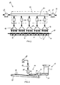
- FIG. 1 is a schematic representation of an apparatus for extruding and cutting material in combination with an apparatus 50 for preventing accumulation of material on the cutter blade according to a first preferred embodiment of the invention.
- a plurality of extrusion dies or die plates 16 are shown with a cutter bar 20 disposed adjacent to the front surfaces or faces of the dies 16.
- Each die plate 16 includes a plurality of die openings 18 through which the material is extruded.
- the die openings 18 are pretzel-shaped and the die plates 16 extrude pretzel dough, the extruded pretzel-shaped length of dough being cut into individual pretzels by the cutter bar 20.
- FIG. 1 While the embodiment in FIG. 1 includes five separate die plates 16 with five die openings 18 in each die plate, it will be recognized that any number of die plates and die openings may be used. Also, the die plates may be in the form of separate members attached to each other or a continuous die plate with openings. Similarly, a continuous cutter bar 20 which simultaneously cuts the extruded dough from each die plate 16 preferably is used; however, more than one cutter bar could be utilized as well.
- the preferred embodiment of an apparatus 50 for preventing material accumulation on the cutter blade includes a pair of air blower units 60 each of which includes an air inlet 62 and an air outlet 64.
- the air is drawn into the inlet 62 where it is pressurized by the blower and exhausted at 64 to the inlet of an air distribution manifold tube 72 located in a manifold housing 70 (shown in phantom in FIG. 1).
- the blower units 60 draw in cool, ambient or room air which air is pressurized and fed to the air distribution manifold tube 72.
- the air distribution manifold tube 72 receives the pressurized air from outlet 64 of blower unit 60 and distributes the pressurized air to a plurality of hot air tools designated by reference numeral 80. As seen in FIGS.
- the pressurized air exits air distribution manifold tube 72 and enters the upper portion of each hot air tool 80.
- the hot air tools 80 have a construction which is known per se, and preferably include a resistance heater over which the pressurized air passes to be heated to the desired temperature.
- the hot air tools 80 feed hot air into distribution nozzles 90, the structure of which is described below, which in turn direct the hot air at the cutter blade 20 to prevent material build up as is discussed further below.
- the air blower unit 60 may be any suitable commercial high pressure blower, for example, a Leister-Robust Pressure Blower, Model 9F.
- the hot air tool 80 which receives and heats air may also have a known construction, for example, a 3300 Leister heater/hot air tool. "Leister" is a registered trade mark.
- FIG. 2 shows an extruder 10 which includes a hopper 12 and a suitable extruding device such as screw 14.
- the die plate 16 is secured to the outlet of the extruder 10 and a cutter 20 is disposed adjacent the face of the die 16.
- the cutter 20 is reciprocated across the die face to cut the extruded material into suitable portions as is known in the art.
- the product portions 40 drop onto a conveyor belt 30 where they are carried to an area (not shown) for further processing.
- the apparatus 50 of the present invention is shown schematically in FIG. 2. As seen by the arrows, the air blower unit 60 feeds air to the hot air tool 80 which in turn heats and feeds the air into the distribution nozzle 90.
- the distribution nozzle 90 is oriented so as to force the hot air directly against the cutter blade 20 and into the face of the die 16.
- two blower units are used with five hot air tools and five distribution nozzles, such is for the sake of clarity only and, depending on the particular application of the invention, various numbers or types of blower units, hot air tools, or distribution nozzles may be used.
- FIG. 3 shows the apparatus 50 mounted on a frame 52 which is movable by means of wheels 53.
- This embodiment of the invention permits the apparatus 50 to be removably positioned adjacent an extruder to prevent accumulation of material on the cutter used with the extruder.
- an apparatus 50 mounted on a movable frame for selective use with any of various extruders, for example, an extruder producing fat-free pretzels.
- the invention permits pre-existing extruders to be retrofitted with apparatus for preventing material build up on the cutter blade of the extruder. Further, such retrofitting could be carried out utilizing an apparatus mounted on a movable stand or other support or by securing an apparatus directly to the extruder.
- the apparatus 50 includes the air distribution manifold housing 70 which may comprise a sheet metal housing in which is located the air distribution manifold tube 72 (as seen in FIG. 4).
- One or more blower units 60 is located on the manifold housing 70 with the inlet 62 thereof open to the surrounding air.
- Suitable electronic controls 54 including wiring 56 are provided to control operation of the blower unit 60 as well as the hot air tools 80 (FIG. 4).
- the frame 52 includes a bracket or like structure 58 which supports the manifold housing 70 and blower unit 60. As best seen in FIG. 4, the blower unit 60 draws air into inlet 62 and feeds pressurized air via outlet 64 into air distribution manifold tube 72.
- the air distribution manifold tube 72 includes a plurality of branched fittings, for example T-fittings 74, which distribute the pressurized air into the inlet of heaters or hot air tools 80.
- the blower units may be replaced by, or utilized with, a compressed air system such as pipes or ducts which convey compressed air to the hot air tools, for example, compressed air which is used to power pneumatic equipment.
- Hot air tools 80 heat the pressurized air and exhaust the air into a channel or pipe member 84, as seen in FIG. 3.
- the channel 84 is rectangular in cross-section.
- the channel 84 terminates at a fan-shaped nozzle 90 which includes an elongated narrow slot or outlet 92.
- the configuration or type of nozzles 90 may be selected based on the particular application of the invention. We have found that in extruding pretzel dough, and particularly fat-free pretzel dough, nozzles 90 in the shape of a flattened funnel with an elongated slot or opening 92 adequately direct the hot air at the center.
- the plurality of hot air tools 80, channels 84 and nozzles 90 may be formed as an integral structure or as separate pieces attached together.
- the nozzles 90 are secured together by struts 94 which fix the relative position of the nozzle outlets 92 so as to ensure proper operation in conjunction with the extruder.
- FIG. 5 shows the apparatus 50 from above; and, as seen therein, the air distribution manifold tube 72 is aligned with the inlets of the hot air tools 80, the outlet of each hot air tool 80 including the curved or arcuate channel 84 which positions the nozzles 90 forwardly of the manifold housing 70.
- the material is extruded through the opening in the die plate and the cutter member 20 is reciprocated across the die face and repeatedly cuts the extruded material into portions.
- the outlet nozzles 90 of apparatus 50 are positioned to force the hot air directly at the cutter blade 20.
- the nozzles 90 direct the air at the top of the face of die plate 16 as seen in FIG. 2.
- the hot air emitted onto the cutter blade and die face prevents accumulation of the material on the die blade even if the apparatus is operated continuously for long periods of time. We conducted several tests to determine the effectiveness of the present invention in preventing dough from building up on a cutter blade and reducing the incidence of required cleaning procedures.
- the velocity of the air produced by the blower varied within the approximate range of 3.56 to 5.08 metres/second (700 to 1000 feet/minute), and the blower was operated at a temperature which resulted in a temperature at the die plate of approximately 66°C ( ⁇ 6°C) (150°F ( ⁇ 10°F)).
- the test ran for 3 hours and 8 minutes, and there was no significant build up of dough on either the knife or the extrusion die and stoppage of the machine to clean the knife was not required.
- the velocity of the hot air generated by the blower unit preferably is within the range of 2.54 to 7.62 metres/second (500 to 1500 feet/minute), and the operating temperature of the blower unit preferably is selected so as to heat the die plate to approximately 66°C ( ⁇ 6°C) (150°F ( ⁇ 10°F)).
- the heater may be set to a temperature within a range of from about 225-275°C (437-527°F). In a most preferred embodiment, the heater temperature is set to approximately 250°C (482°F) and the resulting die plate temperature is approximately 66°C (150°F).
- the hot air distribution fan-shaped nozzles preferably are positioned 1,27 cm (1 ⁇ 2 inch) from the top of the die plate and 15,24 cm (6 inches) away from the die face.
- the temperature and air velocity of the apparatus may be set accordingly, for example by controls provided on each hot air tool 80.
- the position of the nozzles relative to the extruder dies may be adjusted, for example, by adjusting the height or position of the movable support frame.
- the apparatus of the present invention prevents build up of the material on the cutter blade and thus frequent machine stoppages are not necessary. Consequently, this serves to maintain the oven temperature constant during the production of pretzels, which results in a higher quality finished product.
- the invention permits increased efficiency which results in a greater volume of finished product. That is, as there are no frequent production line stoppages to clean the cutter blade, a significantly greater amount of product is able to be produced as compared with prior art systems. It is apparent that the present invention overcomes the problems with the prior art and permits virtually uninterrupted operation of the production lines thereby minimizing the amount of lost product due to line stoppages.
Landscapes
- Life Sciences & Earth Sciences (AREA)
- Engineering & Computer Science (AREA)
- Food Science & Technology (AREA)
- Confectionery (AREA)
- Formation And Processing Of Food Products (AREA)
- Manufacturing And Processing Devices For Dough (AREA)
- Turning (AREA)
- Shearing Machines (AREA)
- Apparatuses For Bulk Treatment Of Fruits And Vegetables And Apparatuses For Preparing Feeds (AREA)
- Crushing And Pulverization Processes (AREA)
Claims (19)
- Procédé pour la production de produits en pâte comprenant :la prévision d'un extrudeur (10) comportant une entrée pour recevoir un approvisionnement de pâte et une sortie, la sortie comprenant une plaque de matrice (16) comportant une face de matrice et une ouverture (18) de matrice qui y est formée qui confère une configuration désirée à la pâte qui est extrudée à travers elle ;la prévision d'un mécanisme de couteau comprenant une lame de couteau (20) disposée adjacente à l'ouverture (18) de matrice pour découper la pâte extrudée ;l'approvisionnement d'une masse de pâte à l'entrée de l'extrudeur (10) ;l'entraínement à force de la masse de pâte à travers l'ouverture (18) de matrice de façon à former une longueur extrudée de pâte ayant une configuration désirée ;l'actionnement d'un mécanisme de couteau pour découper la longueur extrudée de pâte en une pluralité de parcelles de pâte ;la prévision d'un dispositif (60) de soufflage d'air chaud avec une sortie (64) positionnée adjacente à la lame de couteau (20) et à la face de matrice ; etl'action de diriger l'air chaud provenant de la sortie (64) du dispositif de soufflage (60) contre la lame de couteau (20) tout en extrudant et en découpant la longueur extrudée de la pâte de façon à empêcher la pâte de s'accumuler sur la lame de couteau (20).
- Procédé selon la revendication 1, dans lequel la lame de couteau (20) vient au contact de la face de matrice et découpe la longueur extrudée de pâte depuis l'ouverture (18) de la matrice, et l'air chaud est envoyé à force contre la lame de couteau (20) et la face de matrice.
- Procédé selon la revendication 1, dans lequel le dispositif (60) de soufflage d'air chaud comprend au moins un élément de chauffage (80) et au moins une entrée d'air (62), et l'air est soutiré à travers l'entrée (62) et est entraíné à force sur l'élément de chauffage (80) et à travers une buse de sortie (90) contre la lame de couteau (20).
- Procédé selon la revendication 3, dans lequel la buse de sortie (90) comporte une ouverture mince allongée d'air qui dirige l'air chaud contre la lame de couteau (20).
- Procédé selon la revendication 1, dans lequel le dispositif de soufflage d'air chaud (60) est monté sur un support (52) et peut être déplacé par rapport à l'extrudeur (10).
- Procédé selon la revendication 1, dans lequel une lame de couteau continue (20) est prévue adjacente à une pluralité d'ouvertures (18) de matrice de façon à découper la longueur extrudée de pâte qui quitte lesdites ouvertures de matrice (18).
- Procédé selon la revendication 1, dans lequel le dispositif de soufflage d'air chaud (60) comprend une entrée (62) pour recevoir l'air ambiant qui est chauffé et dirigé contre la lame de couteau (20).
- Procédé selon la revendication 1, dans lequel la pâte est une pâte de bretzel et la longueur extrudée de pâte est découpée en bretzels.
- Procédé selon la revendication 1, dans lequel l'air chaud et dirigé sous un angle par rapport au plan de la face de matrice.
- Procédé selon la revendication 1, dans lequel le dispositif de soufflage d'air chaud (60) est maintenu à une température qui chauffe la plaque (16) de matrice à une température qui se situe dans la plage comprise entre environ 60°C et environ 71°C (environ 140°F à environ 160°F).
- Procédé selon la revendication 10, dans lequel la plaque (16) de matrice est chauffée à une température d'environ 66°C (environ 150°F).
- Procédé selon la revendication 10, dans lequel le dispositif de soufflage (60) produit de l'air chaud à une vitesse qui se situe dans une plage comprise entre environ 2,54 et environ 7,62 mètres/seconde (environ 500 à environ 1500 pieds/minute).
- Procédé selon la revendication 12, dans lequel la vitesse est d'environ 5,08 mètres/seconde (environ 1000 pieds/minute).
- Appareil pour l'extrusion d'un matériau et le découpage du matériau extrudé de façon à former une pluralité de parcelles, l'appareil comprenant :caractérisé en ce que le dispositif de soufflage d'air (60) est un dispositif de soufflage d'air chaud qui comprend un dispositif de chauffage (80) qui chauffe l'air sous pression et la buse (90) est disposée en opposition à la lame de couteau (20) et dirige l'air chaud contre la lame de couteau (20) de façon à réduire l'accumulation du matériau sur la lame de couteau (20).un extrudeur (10) comprenant une entrée pour recevoir un approvisionnement de matériau et une sortie, la sortie comprenant une plaque (16) de matrice comportant une face de matrice et une ouverture (18) de matrice à travers laquelle le matériau est extrudé sous une forme désirée ;une lame de couteau (20) pouvant être déplacée disposée adjacente à l'ouverture (18) de matrice et qui est déplacée de façon alternative le long de la face de matrice de façon à découper le matériau qui quitte la sortie de l'extrudeur (10) ; etun dispositif de soufflage d'air (60) positionné adjacent à la lame de couteau (20), le dispositif de soufflage d'air (60) comprenant une buse (90) par laquelle sort de l'air sous pression et qui est positionnée adjacente au couteau et à l'extrudeur,
- Appareil selon la revendication 14, dans lequel la buse (90) comporte une fente de sortie allongée (92) qui dirige un étroit courant d'air chaud contre la lame de couteau (20).
- Appareil selon la revendication 14, dans lequel le dispositif de soufflage d'air chaud (60) est formé comme un dispositif séparé de l'extrudeur (10) et y est fixé de façon amovible.
- Appareil selon la revendication 14, dans lequel une pluralité de sorties de l'extrudeur sont prévues et un dispositif de soufflage d'air chaud séparé (60) est prévu pour chaque sortie séparée avec une buse (90) disposée adjacente à chaque sortie de l'extrudeur.
- Appareil selon la revendication 17, dans lequel la buse (90) disposée adjacente à l'une des sorties de l'extrudeur est reliée à une buse (90) disposée adjacente à au moins une autre sortie de l'extrudeur de façon à fixer la position relative des deux buses (90).
- Appareil selon la revendication 14, dans lequel le dispositif de soufflage d'air chaud (60) aspire l'air ambiant qui est chauffé par le dispositif de chauffage (80) et qui est envoyé en sortie à travers la buse (90).
Applications Claiming Priority (2)
| Application Number | Priority Date | Filing Date | Title |
|---|---|---|---|
| US572237 | 1995-12-13 | ||
| US08/572,237 US5676992A (en) | 1995-12-13 | 1995-12-13 | Process for preventing accumulation of material on a cutting mechanism |
Publications (2)
| Publication Number | Publication Date |
|---|---|
| EP0779031A1 EP0779031A1 (fr) | 1997-06-18 |
| EP0779031B1 true EP0779031B1 (fr) | 2001-06-20 |
Family
ID=24286938
Family Applications (1)
| Application Number | Title | Priority Date | Filing Date |
|---|---|---|---|
| EP96308862A Expired - Lifetime EP0779031B1 (fr) | 1995-12-13 | 1996-12-06 | Dispositif et procédé pour empêcher une accumulation de matériau sur un dispositif de coupe |
Country Status (7)
| Country | Link |
|---|---|
| US (2) | US5676992A (fr) |
| EP (1) | EP0779031B1 (fr) |
| AT (1) | ATE202263T1 (fr) |
| DE (1) | DE69613452T2 (fr) |
| ES (1) | ES2160213T3 (fr) |
| GR (1) | GR3036616T3 (fr) |
| PT (1) | PT779031E (fr) |
Families Citing this family (9)
| Publication number | Priority date | Publication date | Assignee | Title |
|---|---|---|---|---|
| CZ328598A3 (cs) * | 1998-10-13 | 2000-06-14 | V & I, S. R. O. | Způsob výroby krátkých těstovin a zařízení k jeho provádění |
| US20050258643A1 (en) * | 2001-10-03 | 2005-11-24 | Vanderpyl Daniel J | Rotary coupling for air delivery devices |
| US6990751B2 (en) * | 2001-10-03 | 2006-01-31 | Sonic Air Systems, Inc. | Rotatable air knife |
| US20050208183A1 (en) * | 2004-03-16 | 2005-09-22 | Desalegn Emru Y | Method of and apparatus for making ethiopian bread |
| US8377490B2 (en) * | 2005-09-20 | 2013-02-19 | Kraft Foods Global Brands Llc | Method and system for making sliced cheese |
| US20110014311A1 (en) * | 2005-09-20 | 2011-01-20 | Holmes Terry L | Method and system for making extruded portions of cheese |
| US20070065550A1 (en) * | 2005-09-20 | 2007-03-22 | Kraft Foods Holdings, Inc. | Method and system for making shredded cheese |
| WO2009129376A2 (fr) * | 2008-04-16 | 2009-10-22 | Kerry, Inc. | Coextrudeuse comportant une entrée de garniture à partir de l'arrière |
| US8431172B2 (en) | 2008-07-31 | 2013-04-30 | Kraft Foods Global Brands Llc | Production of cookies having large particulates using ultrasonic wirecutting |
Family Cites Families (15)
| Publication number | Priority date | Publication date | Assignee | Title |
|---|---|---|---|---|
| US2039313A (en) * | 1931-08-17 | 1936-05-05 | W E Long Co | Apparatus for protecting sliced bread against mold |
| US3161157A (en) * | 1961-09-14 | 1964-12-15 | Dca Food Ind | Apparatus for producing comestibles |
| US3314381A (en) * | 1962-11-27 | 1967-04-18 | Dca Food Ind | Apparatus for filling baked products |
| US3491637A (en) * | 1966-12-23 | 1970-01-27 | Gen Mills Inc | Cutting apparatus |
| DE1924913A1 (de) * | 1969-01-21 | 1970-07-30 | Laroche & Fils Constr Mec | Schneidemaschine fuer Tabakblaetter,Gewebe,Textilfaden,Textilfasern oder aehnliches Schnittgut |
| US3782876A (en) * | 1971-12-30 | 1974-01-01 | Reading Pretzel Machinery Co | Extrusion machine for pretzels and the like |
| US3981660A (en) * | 1975-02-12 | 1976-09-21 | Fmc Corporation | Apparatus for cutting slices of semi-frozen food products |
| US4300877A (en) * | 1979-01-10 | 1981-11-17 | Sterling Extruder Corp. | Underwater pelletizer |
| US4340343A (en) * | 1981-08-10 | 1982-07-20 | Ugo Mancini | Food preparation machine |
| US4415323A (en) * | 1981-10-27 | 1983-11-15 | Osrow Products Corporation | Pasta-making kitchen appliance with a drying arrangement |
| JPS5879983A (ja) | 1981-11-06 | 1983-05-13 | Kanebo Ltd | 新規なベンズイミダゾ−ル誘導体、その製造法およびその医薬組成物 |
| US4422372A (en) * | 1981-11-12 | 1983-12-27 | Gerber Products Company | Food extruder |
| JPS60219014A (ja) * | 1984-04-16 | 1985-11-01 | Kuraray Co Ltd | チツプ製造装置およびこれを用いたチツプの製造方法 |
| AR243732A1 (es) * | 1990-07-06 | 1993-09-30 | Rolando Jeanneret B | Un aparato de espatula para limpieza del fondo de moldes de chocolate en un proceso de moldeado en superficie fija. |
| US5334407A (en) * | 1993-01-26 | 1994-08-02 | North Dakota State University Research Foundation | Couscous |
-
1995
- 1995-12-13 US US08/572,237 patent/US5676992A/en not_active Expired - Lifetime
-
1996
- 1996-12-06 EP EP96308862A patent/EP0779031B1/fr not_active Expired - Lifetime
- 1996-12-06 AT AT96308862T patent/ATE202263T1/de not_active IP Right Cessation
- 1996-12-06 ES ES96308862T patent/ES2160213T3/es not_active Expired - Lifetime
- 1996-12-06 DE DE69613452T patent/DE69613452T2/de not_active Expired - Fee Related
- 1996-12-06 PT PT96308862T patent/PT779031E/pt unknown
-
1997
- 1997-04-04 US US08/831,851 patent/US5770241A/en not_active Expired - Lifetime
-
2001
- 2001-09-13 GR GR20010401474T patent/GR3036616T3/el not_active IP Right Cessation
Also Published As
| Publication number | Publication date |
|---|---|
| US5770241A (en) | 1998-06-23 |
| ATE202263T1 (de) | 2001-07-15 |
| DE69613452D1 (de) | 2001-07-26 |
| DE69613452T2 (de) | 2002-01-17 |
| PT779031E (pt) | 2001-10-31 |
| ES2160213T3 (es) | 2001-11-01 |
| EP0779031A1 (fr) | 1997-06-18 |
| US5676992A (en) | 1997-10-14 |
| GR3036616T3 (en) | 2001-12-31 |
Similar Documents
| Publication | Publication Date | Title |
|---|---|---|
| EP0779031B1 (fr) | Dispositif et procédé pour empêcher une accumulation de matériau sur un dispositif de coupe | |
| EP0238798B1 (fr) | Appareil pour produire des morceaux de pâte en grande quantité | |
| US8297961B2 (en) | Co-extruder having a filling entrance from the rear | |
| WO1996039847A1 (fr) | Dispositif de decoupage par jet de liquide pour decouper un produit pateux roule | |
| US5435236A (en) | Pneumatic cereal rope conveying and conditioning apparatus | |
| US7374579B2 (en) | System for extruding, cutting in strands, freezing, and chopping a ground food product and method thereof | |
| CA1319477C (fr) | Appareil servant a la fabrication de particules de materiaux thermoplastiques et methode connexe | |
| WO2014139686A1 (fr) | Machine de transformation d'aliment | |
| KR100823366B1 (ko) | 수분 함유 제품의 압출용 장치 | |
| US20200101654A1 (en) | Wire Bank Cutter Assembly | |
| US4212617A (en) | Apparatus for producing a flow of short cheese strands | |
| IE46667B1 (en) | Extrusion head | |
| US4140450A (en) | Apparatus for the production of a product from chopped fibers | |
| US20090123592A1 (en) | Process for preparing vegetable casing and transferring apparatus used therein | |
| US5849347A (en) | Method and apparatus for application of anti-agglomeration particulates onto cut extrudates | |
| EP1161151A1 (fr) | Collecteur-rouleau servant a former une feuille continue de matiere visqueuse | |
| JP2006506956A (ja) | 制御された寸法への食品の成形 | |
| JP4504566B2 (ja) | 押出機をパージする装置 | |
| CN216442612U (zh) | 一种气缸式快速切断装置 | |
| EP0830927A2 (fr) | Procédé et appareil associé pour couper joncs de matière thermoplastique sous forme de granulés au moyen d'un dispositif à jet d'eau | |
| JP2005524405A (ja) | 成形装置及び方法 | |
| EP0661145A1 (fr) | Système de recyclage des déchets hétérogènes en matière plastique pour revêtir des objets métalliques | |
| JPH07118980B2 (ja) | 可変口型ダイ装置 | |
| CN115446893A (zh) | 黏性糕点切割装置 | |
| JPS62138177A (ja) | 食品の押出加工方法及びその装置 |
Legal Events
| Date | Code | Title | Description |
|---|---|---|---|
| PUAI | Public reference made under article 153(3) epc to a published international application that has entered the european phase |
Free format text: ORIGINAL CODE: 0009012 |
|
| AK | Designated contracting states |
Kind code of ref document: A1 Designated state(s): AT BE CH DE DK ES FI FR GB GR IE IT LI LU MC NL PT SE |
|
| 17P | Request for examination filed |
Effective date: 19971206 |
|
| 17Q | First examination report despatched |
Effective date: 19991110 |
|
| GRAG | Despatch of communication of intention to grant |
Free format text: ORIGINAL CODE: EPIDOS AGRA |
|
| GRAG | Despatch of communication of intention to grant |
Free format text: ORIGINAL CODE: EPIDOS AGRA |
|
| GRAH | Despatch of communication of intention to grant a patent |
Free format text: ORIGINAL CODE: EPIDOS IGRA |
|
| GRAH | Despatch of communication of intention to grant a patent |
Free format text: ORIGINAL CODE: EPIDOS IGRA |
|
| GRAA | (expected) grant |
Free format text: ORIGINAL CODE: 0009210 |
|
| AK | Designated contracting states |
Kind code of ref document: B1 Designated state(s): AT BE CH DE DK ES FI FR GB GR IE IT LI LU MC NL PT SE |
|
| PG25 | Lapsed in a contracting state [announced via postgrant information from national office to epo] |
Ref country code: LI Free format text: LAPSE BECAUSE OF FAILURE TO SUBMIT A TRANSLATION OF THE DESCRIPTION OR TO PAY THE FEE WITHIN THE PRESCRIBED TIME-LIMIT Effective date: 20010620 Ref country code: FI Free format text: LAPSE BECAUSE OF FAILURE TO SUBMIT A TRANSLATION OF THE DESCRIPTION OR TO PAY THE FEE WITHIN THE PRESCRIBED TIME-LIMIT Effective date: 20010620 Ref country code: CH Free format text: LAPSE BECAUSE OF FAILURE TO SUBMIT A TRANSLATION OF THE DESCRIPTION OR TO PAY THE FEE WITHIN THE PRESCRIBED TIME-LIMIT Effective date: 20010620 Ref country code: AT Free format text: LAPSE BECAUSE OF FAILURE TO SUBMIT A TRANSLATION OF THE DESCRIPTION OR TO PAY THE FEE WITHIN THE PRESCRIBED TIME-LIMIT Effective date: 20010620 |
|
| REF | Corresponds to: |
Ref document number: 202263 Country of ref document: AT Date of ref document: 20010715 Kind code of ref document: T |
|
| REG | Reference to a national code |
Ref country code: CH Ref legal event code: EP |
|
| ITF | It: translation for a ep patent filed | ||
| REG | Reference to a national code |
Ref country code: IE Ref legal event code: FG4D |
|
| REF | Corresponds to: |
Ref document number: 69613452 Country of ref document: DE Date of ref document: 20010726 |
|
| ET | Fr: translation filed | ||
| PG25 | Lapsed in a contracting state [announced via postgrant information from national office to epo] |
Ref country code: DK Free format text: LAPSE BECAUSE OF FAILURE TO SUBMIT A TRANSLATION OF THE DESCRIPTION OR TO PAY THE FEE WITHIN THE PRESCRIBED TIME-LIMIT Effective date: 20010920 |
|
| REG | Reference to a national code |
Ref country code: PT Ref legal event code: SC4A Free format text: AVAILABILITY OF NATIONAL TRANSLATION Effective date: 20010803 |
|
| REG | Reference to a national code |
Ref country code: ES Ref legal event code: FG2A Ref document number: 2160213 Country of ref document: ES Kind code of ref document: T3 |
|
| PGFP | Annual fee paid to national office [announced via postgrant information from national office to epo] |
Ref country code: SE Payment date: 20011120 Year of fee payment: 6 Ref country code: NL Payment date: 20011120 Year of fee payment: 6 Ref country code: FR Payment date: 20011120 Year of fee payment: 6 |
|
| PGFP | Annual fee paid to national office [announced via postgrant information from national office to epo] |
Ref country code: DE Payment date: 20011123 Year of fee payment: 6 |
|
| PGFP | Annual fee paid to national office [announced via postgrant information from national office to epo] |
Ref country code: GR Payment date: 20011129 Year of fee payment: 6 |
|
| PG25 | Lapsed in a contracting state [announced via postgrant information from national office to epo] |
Ref country code: MC Free format text: LAPSE BECAUSE OF NON-PAYMENT OF DUE FEES Effective date: 20011206 Ref country code: LU Free format text: LAPSE BECAUSE OF NON-PAYMENT OF DUE FEES Effective date: 20011206 Ref country code: IE Free format text: LAPSE BECAUSE OF FAILURE TO SUBMIT A TRANSLATION OF THE DESCRIPTION OR TO PAY THE FEE WITHIN THE PRESCRIBED TIME-LIMIT Effective date: 20011206 |
|
| PGFP | Annual fee paid to national office [announced via postgrant information from national office to epo] |
Ref country code: BE Payment date: 20011221 Year of fee payment: 6 |
|
| REG | Reference to a national code |
Ref country code: CH Ref legal event code: PL |
|
| REG | Reference to a national code |
Ref country code: GB Ref legal event code: IF02 |
|
| PLBE | No opposition filed within time limit |
Free format text: ORIGINAL CODE: 0009261 |
|
| STAA | Information on the status of an ep patent application or granted ep patent |
Free format text: STATUS: NO OPPOSITION FILED WITHIN TIME LIMIT |
|
| 26N | No opposition filed | ||
| REG | Reference to a national code |
Ref country code: IE Ref legal event code: MM4A |
|
| PG25 | Lapsed in a contracting state [announced via postgrant information from national office to epo] |
Ref country code: SE Free format text: LAPSE BECAUSE OF NON-PAYMENT OF DUE FEES Effective date: 20021207 |
|
| PG25 | Lapsed in a contracting state [announced via postgrant information from national office to epo] |
Ref country code: BE Free format text: LAPSE BECAUSE OF NON-PAYMENT OF DUE FEES Effective date: 20021231 |
|
| BERE | Be: lapsed |
Owner name: *RECOT INC. Effective date: 20021231 |
|
| PG25 | Lapsed in a contracting state [announced via postgrant information from national office to epo] |
Ref country code: NL Free format text: LAPSE BECAUSE OF NON-PAYMENT OF DUE FEES Effective date: 20030701 Ref country code: DE Free format text: LAPSE BECAUSE OF NON-PAYMENT OF DUE FEES Effective date: 20030701 |
|
| PG25 | Lapsed in a contracting state [announced via postgrant information from national office to epo] |
Ref country code: GR Free format text: LAPSE BECAUSE OF NON-PAYMENT OF DUE FEES Effective date: 20030707 |
|
| EUG | Se: european patent has lapsed | ||
| NLV4 | Nl: lapsed or anulled due to non-payment of the annual fee |
Effective date: 20030701 |
|
| PG25 | Lapsed in a contracting state [announced via postgrant information from national office to epo] |
Ref country code: FR Free format text: LAPSE BECAUSE OF NON-PAYMENT OF DUE FEES Effective date: 20030901 |
|
| REG | Reference to a national code |
Ref country code: FR Ref legal event code: ST |
|
| PGFP | Annual fee paid to national office [announced via postgrant information from national office to epo] |
Ref country code: PT Payment date: 20031125 Year of fee payment: 8 |
|
| PGFP | Annual fee paid to national office [announced via postgrant information from national office to epo] |
Ref country code: ES Payment date: 20040108 Year of fee payment: 8 |
|
| PGFP | Annual fee paid to national office [announced via postgrant information from national office to epo] |
Ref country code: GB Payment date: 20041201 Year of fee payment: 9 |
|
| PG25 | Lapsed in a contracting state [announced via postgrant information from national office to epo] |
Ref country code: ES Free format text: LAPSE BECAUSE OF NON-PAYMENT OF DUE FEES Effective date: 20041207 |
|
| PG25 | Lapsed in a contracting state [announced via postgrant information from national office to epo] |
Ref country code: PT Free format text: LAPSE BECAUSE OF NON-PAYMENT OF DUE FEES Effective date: 20050606 |
|
| REG | Reference to a national code |
Ref country code: PT Ref legal event code: MM4A Effective date: 20050606 |
|
| PG25 | Lapsed in a contracting state [announced via postgrant information from national office to epo] |
Ref country code: IT Free format text: LAPSE BECAUSE OF NON-PAYMENT OF DUE FEES;WARNING: LAPSES OF ITALIAN PATENTS WITH EFFECTIVE DATE BEFORE 2007 MAY HAVE OCCURRED AT ANY TIME BEFORE 2007. THE CORRECT EFFECTIVE DATE MAY BE DIFFERENT FROM THE ONE RECORDED. Effective date: 20051206 Ref country code: GB Free format text: LAPSE BECAUSE OF NON-PAYMENT OF DUE FEES Effective date: 20051206 |
|
| REG | Reference to a national code |
Ref country code: ES Ref legal event code: FD2A Effective date: 20041207 |
|
| GBPC | Gb: european patent ceased through non-payment of renewal fee |
Effective date: 20051206 |