EP0778637A2 - Verbindungseinheit - Google Patents
Verbindungseinheit Download PDFInfo
- Publication number
- EP0778637A2 EP0778637A2 EP96308734A EP96308734A EP0778637A2 EP 0778637 A2 EP0778637 A2 EP 0778637A2 EP 96308734 A EP96308734 A EP 96308734A EP 96308734 A EP96308734 A EP 96308734A EP 0778637 A2 EP0778637 A2 EP 0778637A2
- Authority
- EP
- European Patent Office
- Prior art keywords
- connector
- wire
- channel
- idc
- main body
- Prior art date
- Legal status (The legal status is an assumption and is not a legal conclusion. Google has not performed a legal analysis and makes no representation as to the accuracy of the status listed.)
- Granted
Links
- 238000003780 insertion Methods 0.000 claims abstract description 6
- 230000037431 insertion Effects 0.000 claims abstract description 6
- 230000014759 maintenance of location Effects 0.000 claims abstract description 3
- 238000006073 displacement reaction Methods 0.000 claims description 10
- 238000009413 insulation Methods 0.000 claims description 10
- 238000003825 pressing Methods 0.000 claims description 2
- 230000001419 dependent effect Effects 0.000 claims 1
- 239000000523 sample Substances 0.000 description 6
- 238000010276 construction Methods 0.000 description 3
- 238000009434 installation Methods 0.000 description 3
- 238000000034 method Methods 0.000 description 3
- 230000015556 catabolic process Effects 0.000 description 1
- 239000004020 conductor Substances 0.000 description 1
- 238000006731 degradation reaction Methods 0.000 description 1
- 230000007613 environmental effect Effects 0.000 description 1
- 239000000499 gel Substances 0.000 description 1
- 230000003993 interaction Effects 0.000 description 1
- 238000004519 manufacturing process Methods 0.000 description 1
- 229920003023 plastic Polymers 0.000 description 1
- 239000004033 plastic Substances 0.000 description 1
- 239000007787 solid Substances 0.000 description 1
Images


Classifications
-
- H—ELECTRICITY
- H01—ELECTRIC ELEMENTS
- H01R—ELECTRICALLY-CONDUCTIVE CONNECTIONS; STRUCTURAL ASSOCIATIONS OF A PLURALITY OF MUTUALLY-INSULATED ELECTRICAL CONNECTING ELEMENTS; COUPLING DEVICES; CURRENT COLLECTORS
- H01R4/00—Electrically-conductive connections between two or more conductive members in direct contact, i.e. touching one another; Means for effecting or maintaining such contact; Electrically-conductive connections having two or more spaced connecting locations for conductors and using contact members penetrating insulation
- H01R4/24—Connections using contact members penetrating or cutting insulation or cable strands
- H01R4/2416—Connections using contact members penetrating or cutting insulation or cable strands the contact members having insulation-cutting edges, e.g. of tuning fork type
- H01R4/242—Connections using contact members penetrating or cutting insulation or cable strands the contact members having insulation-cutting edges, e.g. of tuning fork type the contact members being plates having a single slot
- H01R4/2425—Flat plates, e.g. multi-layered flat plates
- H01R4/2429—Flat plates, e.g. multi-layered flat plates mounted in an insulating base
- H01R4/2433—Flat plates, e.g. multi-layered flat plates mounted in an insulating base one part of the base being movable to push the cable into the slot
-
- H—ELECTRICITY
- H01—ELECTRIC ELEMENTS
- H01R—ELECTRICALLY-CONDUCTIVE CONNECTIONS; STRUCTURAL ASSOCIATIONS OF A PLURALITY OF MUTUALLY-INSULATED ELECTRICAL CONNECTING ELEMENTS; COUPLING DEVICES; CURRENT COLLECTORS
- H01R9/00—Structural associations of a plurality of mutually-insulated electrical connecting elements, e.g. terminal strips or terminal blocks; Terminals or binding posts mounted upon a base or in a case; Bases therefor
- H01R9/22—Bases, e.g. strip, block, panel
- H01R9/24—Terminal blocks
- H01R9/2408—Modular blocks
Definitions
- the present invention relates to a connector unit, particularly but not exclusively for use in telecommunications.
- Exchange pairs emanate from the telephone exchange, and jumper pairs link the exchange pairs (eventually) to a consumer unit.
- exchange pairs are connected to a connector module at the time of installing the telephone network, whereas jumper pairs may be connected, disconnected and reconnected several times as the consumer needs change.
- EP-A-0315345 discloses an electrical connector apparently suitable for use in this context.
- the connector uses insulation displacement contacts (IDC), which are contacts having a blade portion at the tip suitable for piercing the plastics insulation of a wire and making electrical contact with the metallic conductor therewithin.
- IDC insulation displacement contacts
- EP-A-0315345 show an IDC connector having two blade portions, one for interconnection with the jumper wire and one for interconnection with the exchange wire.
- a movable carrier is disclosed which holds the jumper wire and can be forced downwards to bring the enclosed jumper wire into conjunction with the IDC connector. Doing so forces the IDC connector to travel downward into connection with an exchange wire pre-positioned in an internal channel within the connector unit.
- the present invention therefore provides a connector apparatus comprising a base unit and a connector module
- the connector module comprises a head part and a body part, with a bore extending through both and containing the IDC connector, such that force applied to the head part such as to engage the connector unit within the base unit causes the head part to move relative to the body part and hence to move the IDC connector relative thereto.
- the wire receiving means can be a bore, or a channel leading to a bore, into which bore or channel the IDC connector can extend.
- the IDC connector so extends only in certain relative positions of the head part and body part, when the connector module is constructed thereof.
- the connector apparatus is such that tension on a wire engaged with the IDC connector causes the connector module to be removed from the base unit.
- tension on a wire engaged with the IDC connector causes the connector module to be removed from the base unit.
- the wire mentioned above can be an exchange wire of a telecommunications system.
- the present invention therefore provides a connector unit comprising a plug body including a main body part and a head part, the main body and the head part being capable of mutual longitudinal displacement, and
- contact will be made with a pair of wires.
- the insulation displacing tip does not substantially project into the channel, and in the second position it does substantially project into the channel.
- the connector unit is associated with a base unit into which the plug body is insertable, thereby to at least partly cover the channel. More preferably, insertion of the plug body into the base unit entirely encloses the head part, still more preferably partly covers the main body.
- the action of pressing the unit into the base causes mutual displacement of the head portion and main body portion thereby to cause electrical contact to be made between the connector and a wire within the channel.
- the channel runs over the head portion and partly onto the main body.
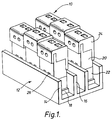
- Figure 1 shows an array of six connector units 10 according to the first embodiment.
- the connectors 10 are supported in a base unit 12 in two rows of three connectors.
- the connectors 10 are generally upright in configuration and are held in the base unit 12 between pairs of opposing walls 14,16. Lateral displacement between the walls 14,16 is prevented by an end stop 18.
- the connectors 10 are constructed from a main body part 20, a head part 22 at one end of the main body part 20, and a cap 24 at the other end.
- the head part 22 is enclosed between the opposed walls 14,16, the main body part 20 projects out from between the walls 14,16 and the cap 24 is presented outermost.
- a pair of channels 26 are formed in the outside surface of the main body 20 and head part 22. These run substantially parallel from approximately the mid portion of the main body 20, along the connector portion 10 to the end of the head part 22, around the end of the head part 22, and then into a small recess (not visible in Figure 1 ) at the rear face of the head 22.
- the channels 26 can be seen more clearly in later figures, but are just visible in Figure 1 above the top of wall 14. Thus, the channels are accessible whilst the connector 10 is installed in the base unit 12.
- Figures 2a and 2b show the connector unit 10 away from the base unit 12.
- the channels 26 are visible insofar as they run along the front face of the connector 10 to the end of the head part 22.
- Figure 3 shows the connector 10 in an exploded form. It can now be seen that the main body part is substantially hollow and that within the connector 10 are a pair of jumper IDC contacts 28 and a pair of exchange IDC contacts 30.
- the exchange contacts 30 are generally elongate and lie within the main body 20 against a rear internal wall thereof. They emanate from the base of the main body 20, have a short dog-leg 32 toward the central axis of the connector 10 and enter the head part 22 through centrally located slots 34.
- the contacts 30 terminate within the head part 22 at an IDC tip 36.
- the length of the IDC tip is sufficient to project a substantial distance into the channel 26b running across the tip of the head part 22, when the head part 22 is snug against the main body part 20.
- the IDC connectors 36 do not so project.
- the jumper connectors 28 are formed in a resilient substantially U-shape with an IDC connector 38 at one tip.
- the U-shaped contacts 28 lie within the internal space of the main body part 20 and their resilience ensures that the side of the U with the IDC tip 38 rests against a front internal wall of the body part 20 (opposed to that against which the exchange contact 30 rests), whilst the other tip of the connector lies resiliently abutting the exchange contact 30.
- the length of the IDC connector 38 is sufficient to project into a slot 40 (not visible in Figure 3) in the cap 24. Intersecting with the slot 40 are a pair of cylindrical recesses 42 into which a jumper pair can be inserted.
- a pair of jumper wires can be inserted into the recesses 42, whereupon downward movement of the cap 24 towards the main body 20 causes the jumper wires to be pressed into the IDC contacts 38, forming a connection.
- a pair of test access openings 44 lie directly above the point of contact between the jumper contacts 28 and the exchange contacts 30. Thus, a probe can be inserted to make electrical contact with one or both of these contacts 28,30, or to separate the contacts 28,30.
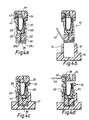
- Figure 4a shows the connector 10 ready for installation.
- the head part 22 is slightly separated from the main body part 20, meaning that the IDC tip 36 of the exchange contact 30 does not project into the recess 26b running beneath the head part 22.
- the channel 26b ends at the rear face of the head 22 in a recess 26c bounded by a relatively thin wall 46.
- the connector unit 10 is shown just prior to installation.
- the tip of an exchange wire 48 has been inserted into the recess 26c and laid along the channel 26b.
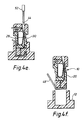
- the connector unit 10 is then positioned over the base unit 12 ready to be placed between the opposed walls 14,16.
- the connector unit 10 is then pressed firmly downward into position between the two walls 14,16.
- the main body part 20 and head part 22 are compressed together, and the IDC tip 36 of the exchange connector 30 is pushed into the channel 26b such that it substantially projects thereinto. Hence, contact is made between the IDC tip 36 and the exchange wire 48.
- the cap 24 is lifted slightly from the body 20, and a jumper wire 50 inserted into the recess 42. Once the jumper wire 50 is fully home, the cap 24 is then pressed downward towards the main body 20, and this causes the IDC tip 38 of the jumper contact 28 to make contact with the jumper wire within the recess 42.
- test probe 52 can be inserted in the test access opening 44, where it can contact the jumper contact 28 and exchange contact 30.
- test probes are known, and include insulating probes which serve to separate the two contacts, solid conducting probes which serve to make electrical contact with both contacts 28,30 simultaneously, and more specialised probes which both separate the contact 28,30, and provide electrical contact with each of the contact 28,30 individually.
- the main body 20 of the connector 10 is gripped and pulled upwards out of the base unit 12. This then allows the exchange wire 48 to be pulled away from the connector unit 10.
- the second embodiment is shown in figures 5 to 8.
- the general construction and operation of the second embodiment bears a close similarity to that of the first, and similar reference numerals have been used to denote this, where possible.
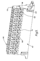
- Figure 5 shows an array of ten connector units 110 according to the second embodiment.
- the connectors 110 are supported in a base unit 112 in a single row of ten connectors. This layout is one commonly used in telephone exchanges.
- the connectors 110 are generally upright in configuration and are held in the base unit 112 between pairs of opposing walls, of which the front wall 114 is visible. Lateral displacement between the walls 114 is prevented by an end stop 118.
- the connector unit 110 is prevented from an accidental removal from the base unit 2, by means of a latch 160.
- This latch 160 is resiliently held by the base unit 112 and engages on a lug 162, visible on figures 6 onwards.
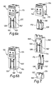
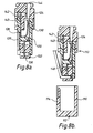
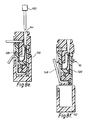
- Figures 6 to 8 shown the connector unit 110 in more detail. It can be seen that it is generally similar to the connector unit 10 shown in figures 2 to 4, but differs most in the interaction between the main body part 120 and the head part 122.
- the body part 120 of the second embodiment shrouds the head part 122 on four sides, with cut-outs 164 at the base of the channels 126 to allow access to wire ports 166 in the head 122.
- the wire ports 126 are blind, and replace the channels 26b of figure 3.
- the body part 120 has a latch 162 for engagement with the catch 160 of the base unit 112. It also has a pair of indents 168 which engage with corresponding protrusions 170 on the cap 124 to hold the cap in either the open (figure 6a) or closed (figure 6b) position.
- the jumper IDC contacts 128 however include a pair of barbs 172 on either side thereof. These engage with internal faces of the body cavity to provide resistance against displacement as the cap 124 is moved from the closed to open position.
- the exchange IDC contacts 130 include a locally raised contact portion 174 which provides the contact portion to the jumper IDC connectors 128. This will usually provide a better electrical contact than a simple plane face as shown in Figure 3.
- the present invention provides a connector unit with a particularly simple construction and few moving parts. At the same time, a versatile connector is provided which should be robust in use.
Landscapes
- Details Of Connecting Devices For Male And Female Coupling (AREA)
- Piezo-Electric Or Mechanical Vibrators, Or Delay Or Filter Circuits (AREA)
- Coupling Device And Connection With Printed Circuit (AREA)
- Brushes (AREA)
- Containers And Packaging Bodies Having A Special Means To Remove Contents (AREA)
- Connector Housings Or Holding Contact Members (AREA)
- Electrotherapy Devices (AREA)
Applications Claiming Priority (4)
| Application Number | Priority Date | Filing Date | Title |
|---|---|---|---|
| GBGB9525128.6A GB9525128D0 (en) | 1995-12-08 | 1995-12-08 | Connector unit |
| GB9525128 | 1995-12-08 | ||
| GB9610396A GB2308020B (en) | 1995-12-08 | 1996-05-17 | Connector unit |
| GB9610396 | 1996-05-17 |
Publications (3)
| Publication Number | Publication Date |
|---|---|
| EP0778637A2 true EP0778637A2 (de) | 1997-06-11 |
| EP0778637A3 EP0778637A3 (de) | 1998-07-01 |
| EP0778637B1 EP0778637B1 (de) | 2006-08-30 |
Family
ID=26308255
Family Applications (1)
| Application Number | Title | Priority Date | Filing Date |
|---|---|---|---|
| EP96308734A Expired - Lifetime EP0778637B1 (de) | 1995-12-08 | 1996-12-03 | Verbindungseinheit |
Country Status (6)
| Country | Link |
|---|---|
| US (1) | US6015312A (de) |
| EP (1) | EP0778637B1 (de) |
| AT (1) | ATE338355T1 (de) |
| AU (1) | AU720657B2 (de) |
| DE (1) | DE69636492T2 (de) |
| GB (1) | GB2345591B (de) |
Cited By (7)
| Publication number | Priority date | Publication date | Assignee | Title |
|---|---|---|---|---|
| WO1999004454A1 (en) * | 1997-07-18 | 1999-01-28 | The Whitaker Corporation | Distribution and interconnection assembly for communications wires |
| WO2001039330A1 (de) * | 1999-11-22 | 2001-05-31 | Krone Gmbh | Stc-modul |
| WO2006036302A1 (en) * | 2004-09-15 | 2006-04-06 | 3M Innovative Properties Company | Connector assembly for housing insulation displacement elements |
| US7101216B2 (en) | 2004-09-15 | 2006-09-05 | 3M Innovative Properties Company | Insulation displacement system for two electrical conductors |
| WO2006125032A3 (en) * | 2005-05-18 | 2007-03-29 | 3M Innovative Properties Co | Electrical connector assembly and method of forming the same |
| US7303446B2 (en) | 2005-05-18 | 2007-12-04 | 3M Innovative Proprties Company | Frame assembly |
| EP3598582A1 (de) * | 2018-07-17 | 2020-01-22 | Schneider Electric Industries SAS | Elektrische verbindungsvorrichtung |
Families Citing this family (23)
| Publication number | Priority date | Publication date | Assignee | Title |
|---|---|---|---|---|
| US6722914B2 (en) * | 2000-01-27 | 2004-04-20 | Ideal Industries, Inc. | Wire connector with extension |
| DE10103107B4 (de) * | 2000-12-20 | 2007-07-12 | Hager Electro Gmbh | Anschlußklemme für elektrische Leiter |
| DE10255674B4 (de) * | 2002-11-28 | 2005-05-04 | Klemsan Elektrik Elektronik San. Ve Tic. A.S. | Reihenklemme mit steckbarem Querbrücker |
| US6672893B1 (en) * | 2002-12-31 | 2004-01-06 | Marconi Communications, Inc. | Modular terminal block assembly |
| JP4100319B2 (ja) * | 2003-10-08 | 2008-06-11 | 住友電装株式会社 | 自動車用のスプライス吸収構造 |
| US7303425B2 (en) * | 2004-03-12 | 2007-12-04 | Channell Commercial Corporation | Electrical connector with filtering device |
| US7018230B2 (en) * | 2004-03-12 | 2006-03-28 | Channell Commercial Corporation | Electrical connector |
| US7303426B2 (en) * | 2004-03-12 | 2007-12-04 | Channell Commercial Corporation | Bridging connector |
| US7458840B2 (en) * | 2004-09-15 | 2008-12-02 | 3M Innovative Properties Company | Cap configured to removably connect to an insulation displacement connector block |
| US7335049B2 (en) * | 2004-09-15 | 2008-02-26 | 3M Innovative Properties Company | Connector assembly for housing insulation displacement elements |
| USD554068S1 (en) | 2004-09-15 | 2007-10-30 | 3M Innovative Properties Company | Cap for an electrical connector |
| US7373719B2 (en) | 2004-11-09 | 2008-05-20 | Channell Commercial Corporation | Method and process for manufacturing a terminal block |
| ITRM20060175A1 (it) * | 2005-04-04 | 2006-10-05 | Mc Technology Gmbh | Elemento di supporto per morsetti di connessione |
| US7331814B2 (en) * | 2005-06-30 | 2008-02-19 | 3M Innovative Properties Company | Apparatus configured to attach to an electrical connector block |
| US7223117B2 (en) * | 2005-06-30 | 2007-05-29 | 3M Innovative Properties Company | Circuit marker apparatus |
| US7165983B1 (en) * | 2005-12-08 | 2007-01-23 | 3M Innovative Properties Company | Access cover configured to receive a testing device |
| DE102006045808B4 (de) * | 2006-09-26 | 2016-02-18 | Erni Production Gmbh & Co. Kg | Steckverbinder mit Zugentlastung |
| US7547226B2 (en) * | 2007-02-22 | 2009-06-16 | Juergen Koessler | Wire connectors for surge protectors and other electrical components |
| US7765695B2 (en) * | 2007-05-29 | 2010-08-03 | Channell Commercial Corporation | Method and process for manufacturing a terminal block |
| GB0910199D0 (en) * | 2009-06-15 | 2009-07-29 | 3M Innovative Properties Co | Symmetrical termination strip for a telecommunications moduel |
| RU2493641C2 (ru) * | 2009-06-15 | 2013-09-20 | 3М Инновейтив Пропертиз Компани | Контактная колодка для телекоммуникационных модулей и способ ее монтажа |
| EP2443703A4 (de) | 2009-06-15 | 2013-05-29 | 3M Innovative Properties Co | Verbindungs- und schaltkontaktelemente für einen anschlussstreifen für ein telekommunikationsmodul |
| US9184515B1 (en) * | 2012-09-28 | 2015-11-10 | Anthony Freakes | Terminal blocks for printed circuit boards |
Citations (1)
| Publication number | Priority date | Publication date | Assignee | Title |
|---|---|---|---|---|
| EP0315345A2 (de) | 1987-11-06 | 1989-05-10 | Nortel Networks Corporation | Elektrische Verbinder |
Family Cites Families (16)
| Publication number | Priority date | Publication date | Assignee | Title |
|---|---|---|---|---|
| CH129741A (de) * | 1926-11-08 | 1928-10-31 | Telefunken Gmbh | Anordnung zur selbsttätigen Herstellung von Verbindungen zwischen Teilnehmern von Niederfrequenz- und Hochfrequenz-Selbstanschlussanlagen. |
| FR646987A (fr) * | 1927-01-12 | 1928-11-19 | Feuille d'étiquettes pour attacher à des marchandises de quantité ou placer près de celles-ci | |
| GB412939A (en) * | 1933-01-03 | 1934-07-03 | Walter Reginald Lambert | Improvements in or relating to holders for electric lamps |
| GB668037A (en) * | 1950-05-22 | 1952-03-12 | Siemens Schuckert Great Britai | Improvements relating to electric switches of the push button type |
| US4688865A (en) * | 1986-04-02 | 1987-08-25 | Teradyne, Inc. | Circuit device for connection to contacts in a row |
| DE3726741C1 (de) * | 1987-08-07 | 1988-09-01 | Krone Ag | Anschlussleiste der Fernmeldetechnik |
| GB8804134D0 (en) * | 1988-02-23 | 1988-03-23 | Raychem Pontoise Sa | Cable connecting module |
| DE3833032A1 (de) * | 1988-09-29 | 1990-04-05 | Quante Fernmeldetechnik Gmbh | Anschlussdose fuer fernsprech-apparate und/oder fernsprech-zusatzgeraete |
| US5181861A (en) * | 1991-02-19 | 1993-01-26 | Lrc Electronics, Inc. | Manually installable coaxial cable connector |
| EP0542164B1 (de) * | 1991-11-14 | 1997-06-04 | Alcatel Components Limited | Elektrischer Verbinderzusammenbau |
| US5302137A (en) * | 1993-04-22 | 1994-04-12 | Reliance Comm/Tec Corporation | Insulation displacement connector terminal block |
| FR2710462B1 (fr) * | 1993-09-20 | 1995-11-10 | Alcatel Cable Interface | Réglette de connexion. |
| FR2710785B1 (fr) * | 1993-09-28 | 1995-11-10 | Alcatel Cable Interface | Dispositif de raccordement fiabilisé. |
| US5451170A (en) * | 1993-09-28 | 1995-09-19 | Reliance Comm/Tec Corporation | Terminal block with protection |
| US5449299A (en) * | 1994-01-24 | 1995-09-12 | Raychem Corporation | Telecommunications terminal |
| FR2718295B1 (fr) * | 1994-03-30 | 1996-04-26 | Alcatel Cable Interface | Poussoir de raccordement et réglette de connexion équipée de tels poussoirs. |
-
1996
- 1996-05-17 GB GB0007044A patent/GB2345591B/en not_active Expired - Fee Related
- 1996-12-03 EP EP96308734A patent/EP0778637B1/de not_active Expired - Lifetime
- 1996-12-03 AT AT96308734T patent/ATE338355T1/de not_active IP Right Cessation
- 1996-12-03 DE DE69636492T patent/DE69636492T2/de not_active Expired - Fee Related
- 1996-12-04 AU AU74126/96A patent/AU720657B2/en not_active Ceased
- 1996-12-06 US US08/761,162 patent/US6015312A/en not_active Expired - Fee Related
Patent Citations (1)
| Publication number | Priority date | Publication date | Assignee | Title |
|---|---|---|---|---|
| EP0315345A2 (de) | 1987-11-06 | 1989-05-10 | Nortel Networks Corporation | Elektrische Verbinder |
Cited By (10)
| Publication number | Priority date | Publication date | Assignee | Title |
|---|---|---|---|---|
| WO1999004454A1 (en) * | 1997-07-18 | 1999-01-28 | The Whitaker Corporation | Distribution and interconnection assembly for communications wires |
| WO2001039330A1 (de) * | 1999-11-22 | 2001-05-31 | Krone Gmbh | Stc-modul |
| WO2006036302A1 (en) * | 2004-09-15 | 2006-04-06 | 3M Innovative Properties Company | Connector assembly for housing insulation displacement elements |
| US7101216B2 (en) | 2004-09-15 | 2006-09-05 | 3M Innovative Properties Company | Insulation displacement system for two electrical conductors |
| WO2006125032A3 (en) * | 2005-05-18 | 2007-03-29 | 3M Innovative Properties Co | Electrical connector assembly and method of forming the same |
| US7303446B2 (en) | 2005-05-18 | 2007-12-04 | 3M Innovative Proprties Company | Frame assembly |
| EP3598582A1 (de) * | 2018-07-17 | 2020-01-22 | Schneider Electric Industries SAS | Elektrische verbindungsvorrichtung |
| FR3084214A1 (fr) * | 2018-07-17 | 2020-01-24 | Schneider Electric Industries Sas | Dispositif de connexion electrique |
| CN110729570A (zh) * | 2018-07-17 | 2020-01-24 | 施耐德电器工业公司 | 电连接装置 |
| CN110729570B (zh) * | 2018-07-17 | 2022-11-04 | 施耐德电器工业公司 | 电连接装置 |
Also Published As
| Publication number | Publication date |
|---|---|
| GB2345591A (en) | 2000-07-12 |
| DE69636492D1 (de) | 2006-10-12 |
| GB0007044D0 (en) | 2000-05-10 |
| AU720657B2 (en) | 2000-06-08 |
| EP0778637A3 (de) | 1998-07-01 |
| DE69636492T2 (de) | 2007-05-24 |
| GB2345591B (en) | 2000-08-23 |
| US6015312A (en) | 2000-01-18 |
| EP0778637B1 (de) | 2006-08-30 |
| ATE338355T1 (de) | 2006-09-15 |
| AU7412696A (en) | 1997-06-12 |
Similar Documents
| Publication | Publication Date | Title |
|---|---|---|
| EP0778637B1 (de) | Verbindungseinheit | |
| KR100238930B1 (ko) | 플러그를 끼울수 있는 모듈 스플라이싱 커넥터 및 브리징 어댑터 | |
| US6368148B1 (en) | Ribbon cable connector with ground bus | |
| CA1098982A (en) | Electrical connector for terminating a plurality of wires and connecting them to other components | |
| US4025141A (en) | Electrical connector block | |
| EP0743707B1 (de) | Verbindermodule | |
| WO1991009436A1 (en) | Modular telephone connector | |
| CA1080314A (en) | Electrical connector for use with multi-conductor cables, and a method of connecting such cables | |
| US6283768B1 (en) | RJ-45 style modular connector | |
| US4315664A (en) | Modular jack | |
| US4221445A (en) | Cross connect distribution system and apparatus | |
| EP0288248B1 (de) | Elektrisches Kontakthalterungssystem, Methode und Werkzeug für sein Entfernen | |
| JPH10504682A (ja) | 分離可能な電線保持具を有したモジュール式コネクタ | |
| EP0775374B1 (de) | Steckverbinder für ein elektrisches kabel | |
| CA1190295A (en) | Electrical termination system and connector member | |
| US6062895A (en) | Patch plug with contact blades | |
| US7097513B2 (en) | Telecommunication connector | |
| EP0615306A2 (de) | Elektrischer Sammelverbinder | |
| US5971792A (en) | Patch plug | |
| US4946406A (en) | Electrical connector which requires no application tool | |
| EP1246317B1 (de) | Anschlussleiste für verknüpfte Leitungen | |
| US6045391A (en) | Multi-pole connecting terminal for electrical conductors | |
| JPH0550108B2 (de) | ||
| AU737992B2 (en) | Connector unit | |
| GB2308020A (en) | connector unit with IDC contact |
Legal Events
| Date | Code | Title | Description |
|---|---|---|---|
| PUAI | Public reference made under article 153(3) epc to a published international application that has entered the european phase |
Free format text: ORIGINAL CODE: 0009012 |
|
| AK | Designated contracting states |
Kind code of ref document: A2 Designated state(s): AT BE CH DE DK ES FI FR GB GR IE IT LI LU MC NL PT SE |
|
| PUAL | Search report despatched |
Free format text: ORIGINAL CODE: 0009013 |
|
| AK | Designated contracting states |
Kind code of ref document: A3 Designated state(s): AT BE CH DE DK ES FI FR GB GR IE IT LI LU MC NL PT SE |
|
| RHK1 | Main classification (correction) |
Ipc: H01R 4/24 |
|
| 17P | Request for examination filed |
Effective date: 19981202 |
|
| 17Q | First examination report despatched |
Effective date: 20020423 |
|
| RAP1 | Party data changed (applicant data changed or rights of an application transferred) |
Owner name: CHANNELL LIMITED |
|
| GRAP | Despatch of communication of intention to grant a patent |
Free format text: ORIGINAL CODE: EPIDOSNIGR1 |
|
| GRAS | Grant fee paid |
Free format text: ORIGINAL CODE: EPIDOSNIGR3 |
|
| GRAA | (expected) grant |
Free format text: ORIGINAL CODE: 0009210 |
|
| AK | Designated contracting states |
Kind code of ref document: B1 Designated state(s): AT BE CH DE DK ES FI FR GB GR IE IT LI LU MC NL PT SE |
|
| PG25 | Lapsed in a contracting state [announced via postgrant information from national office to epo] |
Ref country code: NL Free format text: LAPSE BECAUSE OF FAILURE TO SUBMIT A TRANSLATION OF THE DESCRIPTION OR TO PAY THE FEE WITHIN THE PRESCRIBED TIME-LIMIT Effective date: 20060830 Ref country code: LI Free format text: LAPSE BECAUSE OF FAILURE TO SUBMIT A TRANSLATION OF THE DESCRIPTION OR TO PAY THE FEE WITHIN THE PRESCRIBED TIME-LIMIT Effective date: 20060830 Ref country code: IT Free format text: LAPSE BECAUSE OF FAILURE TO SUBMIT A TRANSLATION OF THE DESCRIPTION OR TO PAY THE FEE WITHIN THE PRESCRIBED TIME-LIMIT;WARNING: LAPSES OF ITALIAN PATENTS WITH EFFECTIVE DATE BEFORE 2007 MAY HAVE OCCURRED AT ANY TIME BEFORE 2007. THE CORRECT EFFECTIVE DATE MAY BE DIFFERENT FROM THE ONE RECORDED. Effective date: 20060830 Ref country code: FI Free format text: LAPSE BECAUSE OF FAILURE TO SUBMIT A TRANSLATION OF THE DESCRIPTION OR TO PAY THE FEE WITHIN THE PRESCRIBED TIME-LIMIT Effective date: 20060830 Ref country code: CH Free format text: LAPSE BECAUSE OF FAILURE TO SUBMIT A TRANSLATION OF THE DESCRIPTION OR TO PAY THE FEE WITHIN THE PRESCRIBED TIME-LIMIT Effective date: 20060830 Ref country code: BE Free format text: LAPSE BECAUSE OF FAILURE TO SUBMIT A TRANSLATION OF THE DESCRIPTION OR TO PAY THE FEE WITHIN THE PRESCRIBED TIME-LIMIT Effective date: 20060830 Ref country code: AT Free format text: LAPSE BECAUSE OF FAILURE TO SUBMIT A TRANSLATION OF THE DESCRIPTION OR TO PAY THE FEE WITHIN THE PRESCRIBED TIME-LIMIT Effective date: 20060830 |
|
| REG | Reference to a national code |
Ref country code: GB Ref legal event code: FG4D |
|
| REG | Reference to a national code |
Ref country code: CH Ref legal event code: EP |
|
| REG | Reference to a national code |
Ref country code: IE Ref legal event code: FG4D |
|
| REF | Corresponds to: |
Ref document number: 69636492 Country of ref document: DE Date of ref document: 20061012 Kind code of ref document: P |
|
| PGFP | Annual fee paid to national office [announced via postgrant information from national office to epo] |
Ref country code: GB Payment date: 20061124 Year of fee payment: 11 |
|
| PG25 | Lapsed in a contracting state [announced via postgrant information from national office to epo] |
Ref country code: SE Free format text: LAPSE BECAUSE OF FAILURE TO SUBMIT A TRANSLATION OF THE DESCRIPTION OR TO PAY THE FEE WITHIN THE PRESCRIBED TIME-LIMIT Effective date: 20061130 Ref country code: DK Free format text: LAPSE BECAUSE OF FAILURE TO SUBMIT A TRANSLATION OF THE DESCRIPTION OR TO PAY THE FEE WITHIN THE PRESCRIBED TIME-LIMIT Effective date: 20061130 |
|
| PG25 | Lapsed in a contracting state [announced via postgrant information from national office to epo] |
Ref country code: IE Free format text: LAPSE BECAUSE OF NON-PAYMENT OF DUE FEES Effective date: 20061204 |
|
| PG25 | Lapsed in a contracting state [announced via postgrant information from national office to epo] |
Ref country code: ES Free format text: LAPSE BECAUSE OF FAILURE TO SUBMIT A TRANSLATION OF THE DESCRIPTION OR TO PAY THE FEE WITHIN THE PRESCRIBED TIME-LIMIT Effective date: 20061211 |
|
| PG25 | Lapsed in a contracting state [announced via postgrant information from national office to epo] |
Ref country code: MC Free format text: LAPSE BECAUSE OF NON-PAYMENT OF DUE FEES Effective date: 20061231 |
|
| PG25 | Lapsed in a contracting state [announced via postgrant information from national office to epo] |
Ref country code: PT Free format text: LAPSE BECAUSE OF FAILURE TO SUBMIT A TRANSLATION OF THE DESCRIPTION OR TO PAY THE FEE WITHIN THE PRESCRIBED TIME-LIMIT Effective date: 20070130 |
|
| PGFP | Annual fee paid to national office [announced via postgrant information from national office to epo] |
Ref country code: DE Payment date: 20070228 Year of fee payment: 11 |
|
| REG | Reference to a national code |
Ref country code: CH Ref legal event code: PL |
|
| NLV1 | Nl: lapsed or annulled due to failure to fulfill the requirements of art. 29p and 29m of the patents act | ||
| ET | Fr: translation filed | ||
| PLBE | No opposition filed within time limit |
Free format text: ORIGINAL CODE: 0009261 |
|
| STAA | Information on the status of an ep patent application or granted ep patent |
Free format text: STATUS: NO OPPOSITION FILED WITHIN TIME LIMIT |
|
| 26N | No opposition filed |
Effective date: 20070531 |
|
| PG25 | Lapsed in a contracting state [announced via postgrant information from national office to epo] |
Ref country code: GR Free format text: LAPSE BECAUSE OF FAILURE TO SUBMIT A TRANSLATION OF THE DESCRIPTION OR TO PAY THE FEE WITHIN THE PRESCRIBED TIME-LIMIT Effective date: 20061201 |
|
| PGFP | Annual fee paid to national office [announced via postgrant information from national office to epo] |
Ref country code: FR Payment date: 20061222 Year of fee payment: 11 |
|
| PG25 | Lapsed in a contracting state [announced via postgrant information from national office to epo] |
Ref country code: LU Free format text: LAPSE BECAUSE OF NON-PAYMENT OF DUE FEES Effective date: 20061203 |
|
| GBPC | Gb: european patent ceased through non-payment of renewal fee |
Effective date: 20071203 |
|
| PG25 | Lapsed in a contracting state [announced via postgrant information from national office to epo] |
Ref country code: DE Free format text: LAPSE BECAUSE OF NON-PAYMENT OF DUE FEES Effective date: 20080701 |
|
| REG | Reference to a national code |
Ref country code: FR Ref legal event code: ST Effective date: 20081020 |
|
| PG25 | Lapsed in a contracting state [announced via postgrant information from national office to epo] |
Ref country code: GB Free format text: LAPSE BECAUSE OF NON-PAYMENT OF DUE FEES Effective date: 20071203 |
|
| PG25 | Lapsed in a contracting state [announced via postgrant information from national office to epo] |
Ref country code: FR Free format text: LAPSE BECAUSE OF NON-PAYMENT OF DUE FEES Effective date: 20071231 |