EP0778196A1 - Control device of a water-jet propulser for a watercraft - Google Patents
Control device of a water-jet propulser for a watercraft Download PDFInfo
- Publication number
- EP0778196A1 EP0778196A1 EP96119265A EP96119265A EP0778196A1 EP 0778196 A1 EP0778196 A1 EP 0778196A1 EP 96119265 A EP96119265 A EP 96119265A EP 96119265 A EP96119265 A EP 96119265A EP 0778196 A1 EP0778196 A1 EP 0778196A1
- Authority
- EP
- European Patent Office
- Prior art keywords
- propulsors
- control
- port
- joystick
- thrust
- Prior art date
- Legal status (The legal status is an assumption and is not a legal conclusion. Google has not performed a legal analysis and makes no representation as to the accuracy of the status listed.)
- Granted
Links
Images


Classifications
-
- B—PERFORMING OPERATIONS; TRANSPORTING
- B63—SHIPS OR OTHER WATERBORNE VESSELS; RELATED EQUIPMENT
- B63H—MARINE PROPULSION OR STEERING
- B63H11/00—Marine propulsion by water jets
- B63H11/02—Marine propulsion by water jets the propulsive medium being ambient water
- B63H11/10—Marine propulsion by water jets the propulsive medium being ambient water having means for deflecting jet or influencing cross-section thereof
-
- B—PERFORMING OPERATIONS; TRANSPORTING
- B63—SHIPS OR OTHER WATERBORNE VESSELS; RELATED EQUIPMENT
- B63H—MARINE PROPULSION OR STEERING
- B63H25/00—Steering; Slowing-down otherwise than by use of propulsive elements; Dynamic anchoring, i.e. positioning vessels by means of main or auxiliary propulsive elements
- B63H25/02—Initiating means for steering, for slowing down, otherwise than by use of propulsive elements, or for dynamic anchoring
-
- B—PERFORMING OPERATIONS; TRANSPORTING
- B63—SHIPS OR OTHER WATERBORNE VESSELS; RELATED EQUIPMENT
- B63H—MARINE PROPULSION OR STEERING
- B63H11/00—Marine propulsion by water jets
- B63H2011/008—Arrangements of two or more jet units
-
- B—PERFORMING OPERATIONS; TRANSPORTING
- B63—SHIPS OR OTHER WATERBORNE VESSELS; RELATED EQUIPMENT
- B63H—MARINE PROPULSION OR STEERING
- B63H25/00—Steering; Slowing-down otherwise than by use of propulsive elements; Dynamic anchoring, i.e. positioning vessels by means of main or auxiliary propulsive elements
- B63H25/02—Initiating means for steering, for slowing down, otherwise than by use of propulsive elements, or for dynamic anchoring
- B63H2025/026—Initiating means for steering, for slowing down, otherwise than by use of propulsive elements, or for dynamic anchoring using multi-axis control levers, or the like, e.g. joysticks, wherein at least one degree of freedom is employed for steering, slowing down, or dynamic anchoring
Definitions
- the present invention relates to a control device of a water-jet propulsor for a watercraft which, in a water-jet propelled watercraft of two propellers, four propellers or more, makes it possible for one person to easily control complicated maneuver operations required when approaching or leaving a pier, by controlling the engine revolution speed (thrust), reverser and deflector angles of the water-jet propulsor by means of a single joystick or the joystick and a heading control dial.
- Japanese Patent Unexamined Publication No. 1-285486 discloses a watercraft control device which, provided with two propulsors capable of freely setting the direction and intensity of thrust, an all-direction controller, such as a single joystick, a selector switch and a steering wheel, controls the direction and intensity of thrust of each propulsor according to the position and the amount of rotating of an operating section of the all-direction controller.
- the all-direction controller and the selector switch are operated to maneuver a vessel for approaching or leaving a pier, that is, to move the vessel transversely or in oblique direction or turn the vessel at a stationary position. But any of these movements requires it to switch the mode which causes discontinuity in the maneuver, reducing the swiftness in maneuver control, and therefore this configuration is not suited for one person carrying out complicated maneuver operations such as in harbor.
- the control device disclosed in Japanese Patent Unexamined Publication No. 6-24388 requires to operate two forward/reverse levers in addition to a steering wheel simultaneously, and therefore has the drawback that maneuver control, such as in harbor, by one-man control is difficult.
- the object of the present invention is to provide a control device for a water-jet propulsor, which enables it to set an appropriate maneuvering force and is suited to complicated maneuver operations which involve many ship maneuvering effectors, such as in harbor.
- a single joystick is installed which is freely movable within a certain control plane with the center of the control plane being designated as a neutral origin, and a plurality of set points being established at operation limit positions in the control plane of the joystick, while a maximum thrust and a maximum deflector angle of each of the main propulsors installed at the port and starboard are set for the plurality of set points, and a command value of thrust and a command value of deflector angle for an intermediate control point in the control plane of the joystick are determined by interpolation between three points, the origin and two set points in a vicinity thereof, so that the forward/reverse thrust and the deflector angles of the port and starboard main propulsors are controlled by means of the single joystick according to the command values.
- auxiliary propulsors each having a reverser mechanism are installed at the port and starboard in the above configuration to constitute a water-jet propelled watercraft of four or a greater number of propellers
- a heading control dial for the pair of auxiliary propulsors is installed near the joystick, while a position of zero rotation angle of the heading control dial is set as a neutral origin and a unit amount of maximum thrust of each auxiliary propulsor are set at laterally symmetrical positions of certain rotation angles, so that forward/reverse thrust of each auxiliary propulsor is controlled independently from the main propulsors by operating the heading control dial.
- a water-jet propelled watercraft of at least four propellers comprising at least a pair of main propulsors, each having a reverser mechanism to control the forward/reverse thrust and a deflector mechanism to control the deflector angle, disposed on the port and starboard sides at the stern and at least a pair of auxiliary propulsors each having a reverser mechanism disposed on the port and starboard sides at the stern, wherein a single joystick is installed which is freely movable within a certain control plane with the center of the control plane being designated as a neutral origin and a plurality of set points being established at operation limit positions in the control plane of the joystick, while a unit amount of maximum thrust of each of the port and starboard main propulsors and auxiliary propulsors and a unit amount of maximum deflector angle of each of the main propulsors are set for the plurality of set points, and
- a heading control dial for each auxiliary propulsor is installed near the joystick, with a position of the zero rotation angle of the heading control dial being set as a neutral origin and a unit amount of maximum thrust of each of the port and starboard auxiliary propulsors being set at laterally symmetrical positions of specified rotation angles, so that forward/reverse thrust of each auxiliary propulsor is controlled by superposing a control command value of the heading control dial and a control command value of the joystick.
- the maneuvering force can be easily increased and therefore water-jet propulsors most suitable for maneuvering large-sized vessels can be obtained.
- the means according to claims 2 through 4 can utilize a turning moment generated by the pair of auxiliary propulsors, maneuvering operations similar to those of the case provided with a bow thruster, namely transverse movement of the vessel and heading about a point near the stern can be done.
- the means according to claim 3, in particular, makes it possible to move the vessel transversely or quickly turning the vessel with a small turning radius by operating the joystick only.
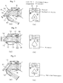
- Figure 1 shows a first embodiment of the invention, with part (a) being a schematic plan view of a 2-propeller water-jet propelled vessel and part (b) being an enlarged perspective view of the stern portion of a vessel provided with two water-jet propulsors.
- Figure 2 shows in part (a) a longitudinal sectional view of the water-jet propulsor in neutral state, and in part (b) a table of command values at this time.
- Figure 3 shows in part (a) is a longitudinal sectional view of the water-jet propulsor in forward state, and in part (b) a table of command values at this time.
- Figure 4 shows in part (a) a longitudinal sectional view of the water-jet propulsor in reverse state, and in part (b) a table of command values at this time.
- Figure 5 is a drawing explaining a combinator control.
- Figure 6 is a drawing showing the operation range of a joystick.
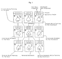
- Figure 7 is a drawing showing command values and cases of maneuver operation in the first embodiment.
- Figure 8 shows a second embodiment of the present invention with part (a) being a schematic drawing of a 4-propeller water-jet propelled watercraft and part (b) being an enlarged perspective view of the stern portion where main propulsors and auxiliary propulsors are installed.
- Figure 9 is a plan view of the stern portion of a 6-propeller water-jet propelled watercraft.
- Figure 10 is a drawing showing command values and cases of a maneuver operation in the second embodiment.
- Figure 11 is a schematic drawing of a 4-propeller water-jet propelled watercraft showing the third embodiment of the invention of the present application.
- Figure 12 is a drawing showing command values and cases of a maneuver operation in the third embodiment.
- the first embodiment of the invention is a case of controlling ship maneuvering effectors by means of only a single joystick in a twin propeller vessel.
- Figure 1 shows a vessel provided with twin engine/twin propeller water-jet propulsors, with (a) being a schematic plan view thereof and (b) being an enlarged perspective view of the stern of a vessel provided with two water-jet propulsors.
- a remote control device including a controller
- a single joystick 1 having all-direction capability is installed thereby to make it easy for one person to maneuver the vessel when approaching or leaving a pier (one-man control).
- the control device 3 is usually installed at each wing out of wheelhouse for the convenience of maneuvering in harbor.
- Each of the two water-jet propulsors (main propulsors) 5, 6 installed at the end of a stern is provided with an engine 4 linked therewith to drive the water-jet propulsor, thereby forming twin engine/twin propeller water-jet propulsion apparatus.
- Revolution speed of each engine 4 and reverser mechanisms R and deflector mechanisms D of the port and starboard main propulsors 5, 6, as shown in Figure 1(b), are controlled by operating the joystick 1. That is, the two water-jet propulsors are constituted as main propulsors having the reverser mechanisms R which control forward/reverse movement and the deflector mechanisms D which control the steering. The two propulsors are disposed symmetrically at port and starboard. Of the two water-jet propulsors, one disposed at the port is also called port unit 5 and one disposed at the starboard is called starboard unit 6.
- Figure 2(a), Figure 3(a) and Figure 4(a) are longitudinal sectional views of the water-jet propulsor, showing the water-jet propulsor in neutral, forward and reverse states, respectively.
- the reverser mechanism R is also called a reverse jet apparatus, and comprises an upper flap 10, a lower flap 11 which are linked to move in coordination by a link mechanism L moved by extending and retracting movements of an actuator (drive cylinder) 9, and a reverse bucket 12.
- the reverse bucket 12 When the vessel moves forward, for example, the reverse bucket 12 is in a horizontal position as shown in Figure 3(a), and the upper and lower flaps 10, 11 are parallel to each other to form maximum discharge aperture 14 therebetween (this is a state of full-forward reverser angle generating the maximum thrust), so that jet stream discharged from a nozzle 18 is spouted straight backward thereby to obtain maximum thrust.
- FIG. 4(a) When moving the vessel backward, the upper and lower flaps 10, 11 are at closing position, as shown in Figure 4(a), and the reverse bucket 12 swings downward to a position where a lower aperture 15 fully opens (this is a state of full-backward reverser angle generating the maximum reverse thrust), so that jet stream hits the upper and lower flaps 10, 11 thereby to be bent downward and is spouted obliquely forward along the reverse bucket 12, 50 that the maximum reverse thrust is obtained.
- Figure 1(h) also shows the state of reverse movement.
- the invention is not limited to the configurations described above, and can be embodied as far as the water-jet propulsor is made in such a configuration that the functions of the reverser mechanism, deflector, etc. similar to those described above can be achieved.
- the deflector mechanism D is also called a horizontal jet angle deflector device, and performs the same function as that of a steering device by pivoting the deflector 13 on a vertical pin 17 on the pump casing 16 side, as shown in Figure 3(a), and horizontally swinging the deflector 13 around the pin 17 by means of another actuator (omitted in the drawing) (the angle of swing is called the deflector angle, while the maximum deflector angle is obtained when the deflector 13 is swung fully to the left or right).
- the actuator is not shown in Figure 2(a) through Figure 3(a) to avoid complication of the drawing.
- Figure 5 shows the relation between the revolution speed RPM of the engine and the reverser angle which are plotted along the ordinate and the thrust which is plotted along the abscissa.
- the reverser angle along the ordinate represents forward motion when it is in the upper half, reverse motion when it is in the lower half, and neutral state when it is 0.
- the neutral state corresponds to the state when the reverser mechanism R is at the position of Figure 2(a).
- intensity of thrust is adjusted by decreasing the engine revolution speed to an idling speed and changing the reverser angle when a low thrust is commanded, and intensity of thrust is adjusted by changing the engine revolution speed with the reverser angle fixed to full-forward or full-reverse state when a high thrust is commanded.
- the joystick 1 is made to be freely movable within the area enclosed in a square in Figure 6, namely within a specified control plane, while the thrust of each main propulsor and the deflector angle are defined by the center (origin) 0 of the control plane, operation limit positions (1), (5) of the joystick in the control plane just above and below the origin, end points (3), (7) to the right and left of the origin and four corners (2), (4), (6), (8) on diagonals between these points, nine set points in all, in the square (not limited to a square, and the control plane may be of circular or other shape).
- the maximum thrust and maximum deflector angle are set to unit amounts (the unit amount means a control command value, and the maximum value is set to 1 in the following embodiments), the thrust being assigned with + sign in the case of forward movement and - sign in the case of reverse movement, and the deflector angle being assigned with + sign in the case of counterclockwise heading and - sign in the case of clockwise heading.
- the unit amount is determined as an intrinsic value for the applied vessel and is usually determined through a simulation. In the above example, the unit amount of maximum thrust of each main propulsor at the eight set points other than the origin is set to 1 (absolute value).
- the deflector angle is set to zero at the origin, set point (1) and set point (5), and the unit amount of maximum deflector angle is set to l (absolute value) at the other set points (2) through (4) and (6) through (8).
- the maneuver control device 3 issues a thrust control value of 1 to a control device (not shown in the drawing) of each main propulsor, thereby controlling the water-jet propulsors to generate maximum thrust (specifically, controlling a hydraulic cylinder 9 of Figure 2).
- the value may be adjusted and changed for the reason of maneuver control.
- the value may be changed from 1 to 0.75 according to the actual state of maneuvering.
- control command values of thrust and deflector angle for each water-jet propulsor are determined instantaneously every time the joystick is operated, by interpolating three points including the origin and the vicinity thereof (the origin and set points (1), (2) in this case).
- thrust and deflector angle at this time are determined by interpolation as follows.
- Values in the upper row are command values of thrust, with the value on the left being a command value for the port propulsor and the value on the right being a command value for the starboard propulsor.
- Values in the lower row are command values of deflector angle.
- the values are expediently set and, in this example, a value 1 means the command value to be given to obtain the maximum thrust or the maximum deflector angle. Therefore, when a command value less than 1 is given, it means that a command value for thrust or deflector angle less than the maximum thrust or the maximum deflector angle is issued from the control device of the maneuver control device 3 to the main propulsors 5, 6.
- the substantially triangular shape schematically represents the water-jet propelled vessel
- black arrow represents the direction (direction of thrust is opposite to this) and intensity of jet stream
- white arrow represents the movement of the vessel.
- the control device at the right above corner indicates the position of the joystick.
- thrust command value of 1 and deflector angle command value of -l are given to both port and starboard propulsors and therefore the port and starboard propulsors produce maximum forward thrust with the deflectors thereof swinging rightward to the maximum deflector angle, thereby to spout the jet obliquely backward and to turn the vessel to the starboard while moving forward.
- thrust command value of 1 and deflector angle command value of 1 are given to the port propulsor while thrust command value of -1 and deflector angle command value of -1 are given to the starboard propulsor. Therefore, the deflector of the port propulsor swings leftward to the maximum deflector angle, and the deflector of the starboard propulsor swings rightward to the maximum deflector angle, thereby to spout the jet obliquely forward to the left. At this time, the vessel moves transversely starboard, but the vessel slowly turns to the port because direction keeping function is not made.
- thrust command value of -l and deflector angle command value of 0 are given to both the port and the starboard propulsors and therefore the jet stream is spouted forward (refer to Figure 4) and maximum reverse thrust is generated so that the vessel moves straight backward.
- thrust command value of -l and deflector angle command value of 1 are given to both the port and the starboard propulsors. Therefore, the deflectors swing to the left and the jet stream is spouted forward obliquely to the right so that the vessel moves backward while turning to the port.
- thrust command value of -l and deflector angle command value of 1 are given to the port propulsor while thrust command value of 1 and deflector angle command value of - l are given to the starboard propulsor. Therefore, the deflector of the port propulsor swings leftward to spout the jet stream obliquely forward to the right and the deflector of the starboard propulsor swings rightward to spout the jet obliquely backward to the right. Therefore, the vessel moves transversely to the port, but the vessel slowly turns to the starboard because direction keeping function is not made.
- thrust command value of 1 and deflector angle command value of 1 are given to both the port and the starboard propulsors. Therefore, the deflectors swing to the left and the jet stream is spouted backward obliquely to the left so that the vessel moves forward while turning to the port.
- thrust command value for the port propulsor is 0.5
- thrust command value for the starboard propulsor is 0.5
- deflector angle of the port propulsor is -0.25
- deflector angle-of the starboard propulsor is -0.25. Therefore, the vessel moves similarly to the state of (2), forward while turning to the starboard, but more slowly (with larger turning radius).
- 4-propeller water-jet propulsors are controlled by means of one joystick and one heading control dial. That is, as shown in Figure 8(a), a remote control device (including a controller) 3 is installed having a joystick of, all-direction capability similar to that described above and a heading control dial 2, to make it easier for one person to control maneuver operations in harbor.
- a remote control device including a controller
- Each of the four water-jet propulsors 5 through 8 installed at the stern end is provided with an engine 4 connected thereto to drive the water-jet propulsor, thereby forming a 4-engine, 4-propeller water-jet propulsion apparatus.
- the propulsor installed inside at the port is called the port main propulsor (inner unit) 5
- the propulsor installed outside at the port is called the port auxiliary propulsor (outer unit) 7
- propulsors disposed symmetrically with these propulsors to form pairs are called starboard main propulsor (inner unit) 6 and starboard auxiliary propulsor (outer unit) 8, respectively.
- two (the pair of inner propulsors 5, 6 in this example) out of the four water-jet propulsors are configured to be main propulsors having reverser mechanisms R for the control of forward/reverse movement and deflector mechanisms D for the control of steering, and the other two propulsors (outer propulsors 7, 8) have reverser mechanisms R only (fixed to be unable to swing horizontally).
- the inner propulsors 5, 6 and the outer propulsors 7, 8 need not necessarily be set to have identical capability, although two propulsors making a pair are preferably set to have identical capability in order to avoid complication of control.
- the joystick 1 is used to control the revolution speeds of the engines 4 of the port and starboard main propulsors 5, 6 and the reverser mechanisms R or the deflector mechanisms D thereof, while the control command values are determined similarly to the case of the first embodiment.
- Installed near the joystick 1 is the heading control dial 2, with the heading control dial 2 being used to control the revolution speeds of the engines 4 of the port and starboard auxiliary propulsors 7, 8 and the reverser mechanisms R.
- the joystick 1 has nothing to do with the control of the auxiliary propulsors 7, 8.
- a position of zero rotation angle of the heading control dial 2 is set as neutral origin of zero thrust and unit amounts of maximum thrusts of the auxiliary propulsors 7, 8 are set at laterally symmetrical positions of certain rotation angle (usually 90 deg.) (refer to Figure 10), so that the forward/reverse thrusts of the auxiliary propulsors 7, 8 can be controlled by operating the heading control dial 2 via the reverser mechanisms of the auxiliary propulsors 7, 8 independently from the main propulsors 7, 8.
- this embodiment is different in that the pair of auxiliary propulsors are added and the heading control dial is installed for the control of the auxiliary propulsors, so that control of the auxiliary propulsors independently from the main propulsors generates only a turning moment.
- FIG 8 shows 4-engine, 4-propeller configuration, while the invention may also be applied to 6-engine, 6-propeller configuration as shown in Figure 9 and 8-engine, 8-propeller configuration not shown in the drawing.
- two or more pairs of main propulsors 5, 6 may be installed.
- Figure 10 shows a part of cases of maneuver control in the above configuration. Only cases of maneuver control not shown in Figure 7 are shown.
- auxiliary propulsors 7, 8 functions similar to that obtained by installing a bow thruster at the bow can be obtained.
- the heading control dial is placed at a position (a)
- thrust is not generated, while rotating the heading control dial by 90 deg. to position (c) causes a command value of -l to be given to the port auxiliary propulsor 7 and command value of +1 to be given to the starboard auxiliary propulsor 8. Signs of these values are inverted when the heading control dial is operated in the opposite direction.
- the heading control dial is placed at an intermediate position (45 deg. rotation) between (a) and (c)
- the command value becomes 0.5. That is, the command value changes linearly according to the rotation angle of the heading control dial.
- the joystick 1 is made free to move in a square control plane, while the center of the control plane is set as neutral origin of zero thrust, unit amounts of thrust of the main propulsors 5, 6 are set at the top and bottom ends of a line segment passing the origin, right and left ends and four corners, eight set points in all, and further the origin and top and bottom ends are set as neutral points of zero deflector angle and unit amounts of deflector angle are set at the right and left ends and the four corners. Also the origin and top and bottom ends are set as neutral points of zero thrust of the auxiliary propulsors 7, 8, and unit amounts of thrusts of the auxiliary propulsors 7, 8 are set at the right and left ends and the four corners, six points in all.
- Command value of thrust and command value of deflector angle for intermediate points in the control plane of the joystick 1 are determined through interpolation of three points including the origin and set points in the vicinity thereof, thereby to control the forward/reverse thrusts and deflector angles of the port and starboard main propulsors 5, 6 and the forward/reverse thrust of the port and starboard auxiliary propulsors 7, 8 by means of one joystick according to the command values.
- Figure 12 shows examples of control command values which are set.
- unit amounts of thrusts given to the main propulsors namely the command values of thrusts
- thrusts of the auxiliary propulsors are zero and deflector angles are zero.
- command value of thrust is 0.5 and deflector angle is -l for the main propulsors
- thrust on the port side is -0.75
- thrust on the starboard is 0.75
- deflector angles on both sides are zero for the auxiliary propulsors.
- Values of 0.5 and 0.75 are not absolute values but related to intrinsic properties of the vessel (center of gravity, maneuvability, etc.
- the cases of maneuver control operations (1) through (8) of Figure 12 are realized by operating one joystick 1.
- Black arrows at the stern in these drawings indicate the direction of jet (direction of thrust is opposite thereto) and the intensity thereof, and white arrows attached to the vessel body indicate the vessel movement similarly to the above. That is, while the cases of maneuver of Figure 7 described previously can be achieved, it is made possible to move the vessel transversely to the port or starboard without turning because direction keeping function is provided at the control points (3) and (7) by installing at least a pair of port and starboard auxiliary propulsors 7, 8. Other operations are similar to those of Figure 7, and description thereof will be omitted.
- the heading control dial of the second embodiment is added to the auxiliary propulsors in the 4-engine, 4-propeller water-jet propulsion apparatus of Figure 11. That is, the heading control dial is installed near the joystick for the pair of port and starboard auxiliary propulsors, while a position of zero rotation angle of the heading control dial is set as neutral origin, and unit amounts of maximum thrusts of the port and starboard auxiliary propulsors are set at laterally symmetrical positions of certain rotation angle (usually 90 deg.). And the forward/reverse thrust is controlled via a reverser mechanism of each auxiliary propulsor by superposing the control command value of the heading control dial and control command value of the joystick. In case the value obtained by superposing both commands exceeds the maximum thrust, the command value is fixed to the maximum thrust.
- the invention can be embodied in such a configuration that the operation direction of the joystick or the heading control dial agrees with the actual movement of the vessel, the control operation agrees with the vessel operator's feeling, making it very easy to operate the vessel. As a result, quick and accurate maneuver control of vessel is made possible, thereby greatly reducing the time required to approach or leave a pier.
- the vessel can be moved transversely and quickly turned with a small radius by operating a single joystick only.
Landscapes
- Chemical & Material Sciences (AREA)
- Engineering & Computer Science (AREA)
- Combustion & Propulsion (AREA)
- Mechanical Engineering (AREA)
- Ocean & Marine Engineering (AREA)
- Mechanical Control Devices (AREA)
- Control Of Vehicle Engines Or Engines For Specific Uses (AREA)
Abstract
Description
- The present invention relates to a control device of a water-jet propulsor for a watercraft which, in a water-jet propelled watercraft of two propellers, four propellers or more, makes it possible for one person to easily control complicated maneuver operations required when approaching or leaving a pier, by controlling the engine revolution speed (thrust), reverser and deflector angles of the water-jet propulsor by means of a single joystick or the joystick and a heading control dial.
- While a water-jet propelled watercraft of a twin engine/twin propeller configuration has been known, in many cases the thrust of each water-jet propulsor (reverser angle and engine revolution speed) and deflector angle are either individually controlled for each propulsor or collectively controlled so that these values of different propulsors are the same in the same direction. In case such a control method is applied to a configuration of the present invention, a 4-engine/4-propeller configuration for example, an individual maneuver control is very difficult because of the great number of ship maneuvering effectors, and a complicated maneuvering, such as in harbor, is impossible with a simple collective control.
- Japanese Patent Unexamined Publication No. 1-285486 discloses a watercraft control device which, provided with two propulsors capable of freely setting the direction and intensity of thrust, an all-direction controller, such as a single joystick, a selector switch and a steering wheel, controls the direction and intensity of thrust of each propulsor according to the position and the amount of rotating of an operating section of the all-direction controller. In the control device of the disclosed configuration, the all-direction controller and the selector switch are operated to maneuver a vessel for approaching or leaving a pier, that is, to move the vessel transversely or in oblique direction or turn the vessel at a stationary position. But any of these movements requires it to switch the mode which causes discontinuity in the maneuver, reducing the swiftness in maneuver control, and therefore this configuration is not suited for one person carrying out complicated maneuver operations such as in harbor.
- The control device disclosed in Japanese Patent Unexamined Publication No. 6-24388 requires to operate two forward/reverse levers in addition to a steering wheel simultaneously, and therefore has the drawback that maneuver control, such as in harbor, by one-man control is difficult.
- The object of the present invention is to provide a control device for a water-jet propulsor, which enables it to set an appropriate maneuvering force and is suited to complicated maneuver operations which involve many ship maneuvering effectors, such as in harbor.
- To achieve the above object, in a control device of a water-jet propulsor for a watercraft according to the invention, a single joystick is installed which is freely movable within a certain control plane with the center of the control plane being designated as a neutral origin, and a plurality of set points being established at operation limit positions in the control plane of the joystick, while a maximum thrust and a maximum deflector angle of each of the main propulsors installed at the port and starboard are set for the plurality of set points, and a command value of thrust and a command value of deflector angle for an intermediate control point in the control plane of the joystick are determined by interpolation between three points, the origin and two set points in a vicinity thereof, so that the forward/reverse thrust and the deflector angles of the port and starboard main propulsors are controlled by means of the single joystick according to the command values.
- In this control device it is preferred that at least a pair of auxiliary propulsors each having a reverser mechanism are installed at the port and starboard in the above configuration to constitute a water-jet propelled watercraft of four or a greater number of propellers, a heading control dial for the pair of auxiliary propulsors is installed near the joystick, while a position of zero rotation angle of the heading control dial is set as a neutral origin and a unit amount of maximum thrust of each auxiliary propulsor are set at laterally symmetrical positions of certain rotation angles, so that forward/reverse thrust of each auxiliary propulsor is controlled independently from the main propulsors by operating the heading control dial.
- In another control device of a water-jet propulsor for a watercraft according to the invention, in a water-jet propelled watercraft of at least four propellers comprising at least a pair of main propulsors, each having a reverser mechanism to control the forward/reverse thrust and a deflector mechanism to control the deflector angle, disposed on the port and starboard sides at the stern and at least a pair of auxiliary propulsors each having a reverser mechanism disposed on the port and starboard sides at the stern, wherein a single joystick is installed which is freely movable within a certain control plane with the center of the control plane being designated as a neutral origin and a plurality of set points being established at operation limit positions in the control plane of the joystick, while a unit amount of maximum thrust of each of the port and starboard main propulsors and auxiliary propulsors and a unit amount of maximum deflector angle of each of the main propulsors are set for the plurality of set points, and a command value of thrust and a command value of deflector angle for an intermediate control point in the control plane of the joystick are determined by interpolation between three points, the origin and two set points in a vicinity thereof, so that the forward/reverse thrusts and the deflector angles of the port and starboard main propulsors and the forward/reverse thrusts of the port and starboard auxiliary propulsors are controlled by means of the single joystick according to the command values.
- In this control device it is preferred that a heading control dial for each auxiliary propulsor is installed near the joystick, with a position of the zero rotation angle of the heading control dial being set as a neutral origin and a unit amount of maximum thrust of each of the port and starboard auxiliary propulsors being set at laterally symmetrical positions of specified rotation angles, so that forward/reverse thrust of each auxiliary propulsor is controlled by superposing a control command value of the heading control dial and a control command value of the joystick.
- With these control devices all maneuver operations in harbor which involve the largest number of ship maneuvering effectors can be carried out by means of only the joystick or by simply operating the heading control dial together with the joystick. Also because such a configuration can be made that the operation direction of the joystick or the heading control dial coincides with the actual direction of the vessel movement, the operation agrees with the vessel operator's feeling so that the maneuvering becomes very easy. As a result, quick and accurate maneuvering is made possible, and the time taken to approach or leave a pier is greatly reduced.
- Because a plurality of water-jet propulsors are provided, the maneuvering force can be easily increased and therefore water-jet propulsors most suitable for maneuvering large-sized vessels can be obtained.
- Also because the means according to
claims 2 through 4 can utilize a turning moment generated by the pair of auxiliary propulsors, maneuvering operations similar to those of the case provided with a bow thruster, namely transverse movement of the vessel and heading about a point near the stern can be done. - The means according to
claim 3, in particular, makes it possible to move the vessel transversely or quickly turning the vessel with a small turning radius by operating the joystick only. - Now preferred embodiments of the present invention will be described below with reference to the accompanying drawings.
- Figure 1 shows a first embodiment of the invention, with part (a) being a schematic plan view of a 2-propeller water-jet propelled vessel and part (b) being an enlarged perspective view of the stern portion of a vessel provided with two water-jet propulsors.
- Figure 2 shows in part (a) a longitudinal sectional view of the water-jet propulsor in neutral state, and in part (b) a table of command values at this time.
- Figure 3 shows in part (a) is a longitudinal sectional view of the water-jet propulsor in forward state, and in part (b) a table of command values at this time.
- Figure 4 shows in part (a) a longitudinal sectional view of the water-jet propulsor in reverse state, and in part (b) a table of command values at this time.
- Figure 5 is a drawing explaining a combinator control.
- Figure 6 is a drawing showing the operation range of a joystick.
- Figure 7 is a drawing showing command values and cases of maneuver operation in the first embodiment.
- Figure 8 shows a second embodiment of the present invention with part (a) being a schematic drawing of a 4-propeller water-jet propelled watercraft and part (b) being an enlarged perspective view of the stern portion where main propulsors and auxiliary propulsors are installed.
- Figure 9 is a plan view of the stern portion of a 6-propeller water-jet propelled watercraft.
- Figure 10 is a drawing showing command values and cases of a maneuver operation in the second embodiment.
- Figure 11 is a schematic drawing of a 4-propeller water-jet propelled watercraft showing the third embodiment of the invention of the present application.
- Figure 12 is a drawing showing command values and cases of a maneuver operation in the third embodiment.
- The first embodiment of the invention is a case of controlling ship maneuvering effectors by means of only a single joystick in a twin propeller vessel. Figure 1 shows a vessel provided with twin engine/twin propeller water-jet propulsors, with (a) being a schematic plan view thereof and (b) being an enlarged perspective view of the stern of a vessel provided with two water-jet propulsors.
- As shown in Figure 1(a), a remote control device (including a controller) 3 provided with a
single joystick 1 having all-direction capability is installed thereby to make it easy for one person to maneuver the vessel when approaching or leaving a pier (one-man control). Thecontrol device 3 is usually installed at each wing out of wheelhouse for the convenience of maneuvering in harbor. Each of the two water-jet propulsors (main propulsors) 5, 6 installed at the end of a stern is provided with anengine 4 linked therewith to drive the water-jet propulsor, thereby forming twin engine/twin propeller water-jet propulsion apparatus. Revolution speed of eachengine 4 and reverser mechanisms R and deflector mechanisms D of the port and starboardmain propulsors joystick 1. That is, the two water-jet propulsors are constituted as main propulsors having the reverser mechanisms R which control forward/reverse movement and the deflector mechanisms D which control the steering. The two propulsors are disposed symmetrically at port and starboard. Of the two water-jet propulsors, one disposed at the port is also calledport unit 5 and one disposed at the starboard is calledstarboard unit 6. - Figure 2(a), Figure 3(a) and Figure 4(a) are longitudinal sectional views of the water-jet propulsor, showing the water-jet propulsor in neutral, forward and reverse states, respectively. In the drawing, the reverser mechanism R is also called a reverse jet apparatus, and comprises an
upper flap 10, alower flap 11 which are linked to move in coordination by a link mechanism L moved by extending and retracting movements of an actuator (drive cylinder) 9, and areverse bucket 12. When the vessel moves forward, for example, thereverse bucket 12 is in a horizontal position as shown in Figure 3(a), and the upper andlower flaps maximum discharge aperture 14 therebetween (this is a state of full-forward reverser angle generating the maximum thrust), so that jet stream discharged from anozzle 18 is spouted straight backward thereby to obtain maximum thrust. When moving the vessel backward, the upper andlower flaps reverse bucket 12 swings downward to a position where alower aperture 15 fully opens (this is a state of full-backward reverser angle generating the maximum reverse thrust), so that jet stream hits the upper andlower flaps reverse bucket 12, 50 that the maximum reverse thrust is obtained. Figure 1(h) also shows the state of reverse movement. The invention is not limited to the configurations described above, and can be embodied as far as the water-jet propulsor is made in such a configuration that the functions of the reverser mechanism, deflector, etc. similar to those described above can be achieved. - The deflector mechanism D is also called a horizontal jet angle deflector device, and performs the same function as that of a steering device by pivoting the
deflector 13 on avertical pin 17 on thepump casing 16 side, as shown in Figure 3(a), and horizontally swinging thedeflector 13 around thepin 17 by means of another actuator (omitted in the drawing) (the angle of swing is called the deflector angle, while the maximum deflector angle is obtained when thedeflector 13 is swung fully to the left or right). The actuator is not shown in Figure 2(a) through Figure 3(a) to avoid complication of the drawing. - As shown in Figure 5, the thrusts of the port and starboard main propulsors are controlled by the combination of the reverser angle and the revolution speed of the main engine, in the so-called combinator control method (the same applies also to the auxiliary propulsors to be described later). Figure 5 shows the relation between the revolution speed RPM of the engine and the reverser angle which are plotted along the ordinate and the thrust which is plotted along the abscissa. The reverser angle along the ordinate represents forward motion when it is in the upper half, reverse motion when it is in the lower half, and neutral state when it is 0. The neutral state corresponds to the state when the reverser mechanism R is at the position of Figure 2(a). The right half of the abscissa represents forward thrust and the left half of the abscissa represents reverse thrust. As will be understood from this drawing, in the combinator control method, intensity of thrust is adjusted by decreasing the engine revolution speed to an idling speed and changing the reverser angle when a low thrust is commanded, and intensity of thrust is adjusted by changing the engine revolution speed with the reverser angle fixed to full-forward or full-reverse state when a high thrust is commanded.
- The
joystick 1 is made to be freely movable within the area enclosed in a square in Figure 6, namely within a specified control plane, while the thrust of each main propulsor and the deflector angle are defined by the center (origin) 0 of the control plane, operation limit positions (1), (5) of the joystick in the control plane just above and below the origin, end points (3), (7) to the right and left of the origin and four corners (2), (4), (6), (8) on diagonals between these points, nine set points in all, in the square (not limited to a square, and the control plane may be of circular or other shape). Usually, the maximum thrust and maximum deflector angle are set to unit amounts (the unit amount means a control command value, and the maximum value is set to 1 in the following embodiments), the thrust being assigned with + sign in the case of forward movement and - sign in the case of reverse movement, and the deflector angle being assigned with + sign in the case of counterclockwise heading and - sign in the case of clockwise heading. The unit amount is determined as an intrinsic value for the applied vessel and is usually determined through a simulation. In the above example, the unit amount of maximum thrust of each main propulsor at the eight set points other than the origin is set to 1 (absolute value). The deflector angle is set to zero at the origin, set point (1) and set point (5), and the unit amount of maximum deflector angle is set to l (absolute value) at the other set points (2) through (4) and (6) through (8). When thejoystick 1 is positioned at set point (1), for example, themaneuver control device 3 issues a thrust control value of 1 to a control device (not shown in the drawing) of each main propulsor, thereby controlling the water-jet propulsors to generate maximum thrust (specifically, controlling ahydraulic cylinder 9 of Figure 2). - At a certain set point, the value may be adjusted and changed for the reason of maneuver control. For example, the value may be changed from 1 to 0.75 according to the actual state of maneuvering.
- When the
joystick 1 is at an intermediate operation point, for example at point A in Figure 6, control command values of thrust and deflector angle for each water-jet propulsor are determined instantaneously every time the joystick is operated, by interpolating three points including the origin and the vicinity thereof (the origin and set points (1), (2) in this case). When thejoystick 1 is turned frompoint 0 by 1/2 forward and 1/4 to the right thereby to be positioned at point A, for example, thrust and deflector angle at this time are determined by interpolation as follows.
- Nine cases of maneuvering a vessel shown in Figure 7 are realized with the configuration described above. Values in the upper row are command values of thrust, with the value on the left being a command value for the port propulsor and the value on the right being a command value for the starboard propulsor. Values in the lower row are command values of deflector angle. As described previously, the values are expediently set and, in this example, a
value 1 means the command value to be given to obtain the maximum thrust or the maximum deflector angle. Therefore, when a command value less than 1 is given, it means that a command value for thrust or deflector angle less than the maximum thrust or the maximum deflector angle is issued from the control device of themaneuver control device 3 to themain propulsors - In the drawing, the substantially triangular shape schematically represents the water-jet propelled vessel, black arrow represents the direction (direction of thrust is opposite to this) and intensity of jet stream and white arrow represents the movement of the vessel. The control device at the right above corner indicates the position of the joystick.
- Among the diagrams showing nine cases of maneuver of Figure 7, the diagram at the center shows the state of neutral because the joystick is positioned at the
origin 0, while the water-jet propulsor at this time is in a state shown in Figure 2(a). Numbers in ( ) in Figure 7 correspond to the positions where the joystick is placed in Figure 6. The same applies to the description that follows. - When the joystick is placed in position (1) of Figure 6, both the port and starboard propulsors are in the state shown in Figure 3(a), with the jet stream spouted backward thereby to obtain forward thrust. In this case, because the command value is 1, maximum forward thrust is generated, and the vessel moves in the direction of the white arrow.
- When the joystick is placed in position (2) of Figure 6 (top right corner), thrust command value of 1 and deflector angle command value of -l are given to both port and starboard propulsors and therefore the port and starboard propulsors produce maximum forward thrust with the deflectors thereof swinging rightward to the maximum deflector angle, thereby to spout the jet obliquely backward and to turn the vessel to the starboard while moving forward.
- When the joystick is placed in position (3) of Figure 6 (right of origin), thrust command value of 1 and deflector angle command value of 1 are given to the port propulsor while thrust command value of -1 and deflector angle command value of -1 are given to the starboard propulsor. Therefore, the deflector of the port propulsor swings leftward to the maximum deflector angle, and the deflector of the starboard propulsor swings rightward to the maximum deflector angle, thereby to spout the jet obliquely forward to the left. At this time, the vessel moves transversely starboard, but the vessel slowly turns to the port because direction keeping function is not made.
- When the joystick is placed in position (4) of Figure 6 (right bottom corner), thrust command value of -1 and deflector angle command value of -l are given to both the port and starboard propulsors. Therefore the deflectors of both the port and the starboard propulsors swing rightward to the maximum deflector angle, thereby to spout the jet obliquely upward to the left to turn the vessel to the starboard while moving backward.
- When the joystick is placed in position (5) of Figure 6, thrust command value of -l and deflector angle command value of 0 are given to both the port and the starboard propulsors and therefore the jet stream is spouted forward (refer to Figure 4) and maximum reverse thrust is generated so that the vessel moves straight backward.
- When the joystick is placed in position (6) of Figure 6, thrust command value of -l and deflector angle command value of 1 are given to both the port and the starboard propulsors. Therefore, the deflectors swing to the left and the jet stream is spouted forward obliquely to the right so that the vessel moves backward while turning to the port.
- When the joystick is placed in position (7) of Figure 6, thrust command value of -l and deflector angle command value of 1 are given to the port propulsor while thrust command value of 1 and deflector angle command value of - l are given to the starboard propulsor. Therefore, the deflector of the port propulsor swings leftward to spout the jet stream obliquely forward to the right and the deflector of the starboard propulsor swings rightward to spout the jet obliquely backward to the right. Therefore, the vessel moves transversely to the port, but the vessel slowly turns to the starboard because direction keeping function is not made.
- When the joystick is placed in position (8) of Figure 6, thrust command value of 1 and deflector angle command value of 1 are given to both the port and the starboard propulsors. Therefore, the deflectors swing to the left and the jet stream is spouted backward obliquely to the left so that the vessel moves forward while turning to the port.
- When the joystick is placed in the point A (intermediate position) of Figure 6, thrust command value for the port propulsor is 0.5, thrust command value for the starboard propulsor is 0.5, deflector angle of the port propulsor is -0.25 and deflector angle-of the starboard propulsor is -0.25. Therefore, the vessel moves similarly to the state of (2), forward while turning to the starboard, but more slowly (with larger turning radius).
- In the second embodiment of the invention, 4-propeller water-jet propulsors are controlled by means of one joystick and one heading control dial. That is, as shown in Figure 8(a), a remote control device (including a controller) 3 is installed having a joystick of, all-direction capability similar to that described above and a heading
control dial 2, to make it easier for one person to control maneuver operations in harbor. Each of the four water-jet propulsors 5 through 8 installed at the stern end is provided with anengine 4 connected thereto to drive the water-jet propulsor, thereby forming a 4-engine, 4-propeller water-jet propulsion apparatus. The propulsor installed inside at the port (near to the center of vessel) is called the port main propulsor (inner unit) 5, the propulsor installed outside at the port is called the port auxiliary propulsor (outer unit) 7, while propulsors disposed symmetrically with these propulsors to form pairs are called starboard main propulsor (inner unit) 6 and starboard auxiliary propulsor (outer unit) 8, respectively. - As shown in Figure 8(b), two (the pair of
inner propulsors outer propulsors 7, 8) have reverser mechanisms R only (fixed to be unable to swing horizontally). Theinner propulsors outer propulsors - The
joystick 1 is used to control the revolution speeds of theengines 4 of the port and starboardmain propulsors joystick 1 is the headingcontrol dial 2, with the headingcontrol dial 2 being used to control the revolution speeds of theengines 4 of the port and starboardauxiliary propulsors joystick 1 has nothing to do with the control of theauxiliary propulsors control dial 2 is set as neutral origin of zero thrust and unit amounts of maximum thrusts of theauxiliary propulsors auxiliary propulsors control dial 2 via the reverser mechanisms of theauxiliary propulsors main propulsors - When compared to the first embodiment, this embodiment is different in that the pair of auxiliary propulsors are added and the heading control dial is installed for the control of the auxiliary propulsors, so that control of the auxiliary propulsors independently from the main propulsors generates only a turning moment.
- Figure 8 shows 4-engine, 4-propeller configuration, while the invention may also be applied to 6-engine, 6-propeller configuration as shown in Figure 9 and 8-engine, 8-propeller configuration not shown in the drawing. In case it is necessary to enhance the capability of the main propulsors, two or more pairs of
main propulsors - Figure 10 shows a part of cases of maneuver control in the above configuration. Only cases of maneuver control not shown in Figure 7 are shown. By installing the
auxiliary propulsors auxiliary propulsor 7 and command value of +1 to be given to the starboardauxiliary propulsor 8. Signs of these values are inverted when the heading control dial is operated in the opposite direction. When the heading control dial is placed at an intermediate position (45 deg. rotation) between (a) and (c), the command value becomes 0.5. That is, the command value changes linearly according to the rotation angle of the heading control dial. - As shown in Figure 10, in case the joystick is held at the neutral position and the heading control dial is placed at position (c), directions of the jet streams from the port and starboard auxiliary propulsors are reversed (reverse thrust for the port and forward thrust for the starboard), so that the vessel turns to the port at the place. When the heading control dial is placed at position (d) which is symmetrical with (c), the vessel turns to the starboard.
- On the other hand, when the
joystick 1 is turned to the righthand side and the heading control dial is placed at point (b) direction keeping function is added to the case of maneuver control (7) of Figure 7, so that the vessel moves transversely right to the port. Similarly, when the joystick and the heading control dial are placed at positions symmetrical to the above, direction keeping function is added to the case of maneuver control (3) of Figure 7, so that the vessel moves transversely right to the starboard. Thus a function similar to that obtained by installing a bow thruster at the bow can be obtained by installing theauxiliary propulsors - In this embodiment, although 4-engine, 4-propeller configuration is employed similarly to the second embodiment as shown in Figure 11, the heading control dial is not provided and the
main propulsors auxiliary propulsors - The
joystick 1 is made free to move in a square control plane, while the center of the control plane is set as neutral origin of zero thrust, unit amounts of thrust of themain propulsors auxiliary propulsors auxiliary propulsors joystick 1 are determined through interpolation of three points including the origin and set points in the vicinity thereof, thereby to control the forward/reverse thrusts and deflector angles of the port and starboardmain propulsors auxiliary propulsors - Figure 12 shows examples of control command values which are set. When the joystick is placed at control point (1) or (2), for example, unit amounts of thrusts given to the main propulsors, namely the command values of thrusts, are maximum values of 1 or -1, while thrusts of the auxiliary propulsors are zero and deflector angles are zero. At the control point of (2), command value of thrust is 0.5 and deflector angle is -l for the main propulsors, while thrust on the port side is -0.75 and thrust on the starboard is 0.75 and deflector angles on both sides are zero for the auxiliary propulsors. Values of 0.5 and 0.75 are not absolute values but related to intrinsic properties of the vessel (center of gravity, maneuvability, etc. determined by vessel type, vessel model, width, length and other elements). Because the command values of Figure 12 are determined through a simulation under general conditions, and therefore the value 0.75, for example, may be changed to 1 by the captain onboard in case the vessel movement does not conform to the requirements. In this case, only little changes in the vessel movement is caused (for example, the radius of turning of the vessel changes).
- In the control device having the control functions described above, the cases of maneuver control operations (1) through (8) of Figure 12 are realized by operating one
joystick 1. Black arrows at the stern in these drawings indicate the direction of jet (direction of thrust is opposite thereto) and the intensity thereof, and white arrows attached to the vessel body indicate the vessel movement similarly to the above. That is, while the cases of maneuver of Figure 7 described previously can be achieved, it is made possible to move the vessel transversely to the port or starboard without turning because direction keeping function is provided at the control points (3) and (7) by installing at least a pair of port and starboardauxiliary propulsors - In this embodiment, although not shown in the drawing, similarly to the third embodiment, the heading control dial of the second embodiment (Figure 8) is added to the auxiliary propulsors in the 4-engine, 4-propeller water-jet propulsion apparatus of Figure 11. That is, the heading control dial is installed near the joystick for the pair of port and starboard auxiliary propulsors, while a position of zero rotation angle of the heading control dial is set as neutral origin, and unit amounts of maximum thrusts of the port and starboard auxiliary propulsors are set at laterally symmetrical positions of certain rotation angle (usually 90 deg.). And the forward/reverse thrust is controlled via a reverser mechanism of each auxiliary propulsor by superposing the control command value of the heading control dial and control command value of the joystick. In case the value obtained by superposing both commands exceeds the maximum thrust, the command value is fixed to the maximum thrust.
- According to the invention of
claims 1 through 4, because all maneuver operations in harbor involving the greatest number of ship maneuvering effectors can be carried out by operating only the joystick or the joystick and the heading control dial to control a plurality of water-jet propulsors, a control device of water-jet propulsion apparatus most suitable for one-man control can be realized. - Also because the invention can be embodied in such a configuration that the operation direction of the joystick or the heading control dial agrees with the actual movement of the vessel, the control operation agrees with the vessel operator's feeling, making it very easy to operate the vessel. As a result, quick and accurate maneuver control of vessel is made possible, thereby greatly reducing the time required to approach or leave a pier.
- Because a plurality of water-jet propulsors are provided, maneuvering force can be easily increased and a water-jet propulsion apparatus suited to maneuvering large-sized vessels can be obtained.
- According to the invention of
claims 2 through 4, in particular, because turning moment generated by a pair of auxiliary propulsors can be utilized, it is made possible to carry out maneuver operations similar to those in the case of installing a bow thruster, namely moving the vessel transversely or turning the vessel around a stationary point near the stern. - According to the invention of
claim 3, in particular, the vessel can be moved transversely and quickly turned with a small radius by operating a single joystick only.
Claims (4)
- A control device of a water-jet propulsor for a watercraft which is used in a water-jet propelled watercraft comprising at least a pair of main propulsors each having a reverser mechanism to control the forward/reverse thrust and a deflector mechanism to control the deflector angle, disposed on the port and starboard sides at the stern, wherein a single joystick is installed which is freely movable within a certain control plane with the center of the control plane being designated as a neutral origin and a plurality of set points being established at operation limit positions in the control plane of the joystick, while a unit amount of a maximum thrust and a maximum deflector angle of each of the main propulsors installed at the port and starboard sides are set for the plurality of set points, and a command value of thrust and a command value of deflector angle are determined by interpolation between three points, namely the origin and two points in a vicinity thereof, for any intermediate set point in the control plane of the joystick, so that the forward/reverse thrust and the deflector angle of the port and starboard main propulsors are controlled by means of the single joystick according to the command values.
- A control device according to claim 1, wherein at least a pair of auxiliary propulsors, each having a reverser mechanism, are disposed on the port and starboard sides are further added to the configuration of claim 1 thereby to constitute water-jet propelled watercraft of four or more propellers, while a heading control dial for the pair of auxiliary propulsors is installed near the joystick with a position of zero rotation angle of the heading control dial being set as a neutral origin and unit amount of maximum thrust of each of the auxiliary propulsors being set at laterally symmetrical positions of specified rotation angles, so that forward/reverse thrust of each auxiliary propulsor is controlled independently from the main propulsors by operating the heading control dial.
- A control device of a water-jet propulsor for a watercraft which, in a water-jet propelled watercraft of four or more propellers comprising at least a pair of port and starboard main propulsors, each having a reverser mechanism to control the forward/reverse thrust and a deflector mechanism to control the deflector angle, and at least a pair of port and starboard auxiliary propulsors each having a reverser mechanism, both pairs being disposed at the stern, wherein a single joystick is installed which is freely movable within a certain control plane with the center of the control plane being designated as a neutral origin and a plurality of set points being established at operation limit positions in the control plane of the joystick, while unit amount of maximum thrust of each of the main propulsors and the auxiliary propulsors installed at the port and starboard and unit amount of maximum deflector angle of each of the main propulsors are set for the plurality of set points, and command value of thrust and command value of deflector angle for any intermediate set point in the control plane of the joystick are determined by interpolation between three points, the origin and two points in a vicinity thereof, so that the forward/reverse thrusts and the deflector angles of the port and starboard main propulsors and the forward/reverse thrusts of the port and starboard auxiliary propulsors are controlled by means of the single joystick according to the command values.
- The control device according to claim 3, wherein a heading control dial for each auxiliary propulsor is installed near the joystick with a position of zero rotation angle of the heading control dial being set as a neutral origin and unit amount of maximum thrust of each of the port and starboard auxiliary propulsors being set at laterally symmetrical positions of specified rotation angles, so that forward/reverse thrust of each auxiliary propulsor is controlled by superposing a control command value of the heading control dial and a control command value of the joystick.
Applications Claiming Priority (3)
| Application Number | Priority Date | Filing Date | Title |
|---|---|---|---|
| JP320078/95 | 1995-12-08 | ||
| JP32007895 | 1995-12-08 | ||
| JP7320078A JP2788216B2 (en) | 1995-12-08 | 1995-12-08 | Control device for marine water jet propulsion |
Publications (2)
| Publication Number | Publication Date |
|---|---|
| EP0778196A1 true EP0778196A1 (en) | 1997-06-11 |
| EP0778196B1 EP0778196B1 (en) | 2000-04-05 |
Family
ID=18117479
Family Applications (1)
| Application Number | Title | Priority Date | Filing Date |
|---|---|---|---|
| EP19960119265 Expired - Lifetime EP0778196B1 (en) | 1995-12-08 | 1996-12-02 | Control device of a water-jet propulser for a watercraft |
Country Status (3)
| Country | Link |
|---|---|
| EP (1) | EP0778196B1 (en) |
| JP (1) | JP2788216B2 (en) |
| DE (1) | DE69607573T2 (en) |
Cited By (25)
| Publication number | Priority date | Publication date | Assignee | Title |
|---|---|---|---|---|
| DE19804661A1 (en) * | 1998-02-06 | 1999-08-19 | Schoenwaelder | Side wall air cushion water craft |
| DE19856305A1 (en) * | 1998-12-07 | 2000-06-08 | Dirk Buechler | Ship propulsion |
| DE19963476A1 (en) * | 1999-12-28 | 2001-07-19 | Peter Mueller | Hand lever control for motor and sports boats |
| WO2001034463A3 (en) * | 1999-11-09 | 2001-10-04 | Cwf Hamilton & Co Ltd | Improvements relating to waterjet control systems |
| EP1208040A1 (en) * | 1999-08-19 | 2002-05-29 | The Talaria Company, LLC | Autopilot-based steering and maneuvering system for boats |
| WO2003026955A3 (en) * | 2001-09-28 | 2003-09-18 | Vector Controls Inc | Method and apparatus for controlling a waterjet-driven marine vessel |
| EP1364870A1 (en) * | 2002-05-20 | 2003-11-26 | Kawasaki Jukogyo Kabushiki Kaisha | Method and device for allocating thrust to air or water craft |
| DE10357309A1 (en) * | 2003-12-05 | 2005-07-07 | Schönwälder, Joachim, Dipl.-Ing. | Ship or boat propulsion pipe for driving a vessel using a reaction force has a pressurized water jet for accelerating water in the pipe and creating a reaction force for propelling the vessel |
| US7052338B2 (en) | 2001-08-06 | 2006-05-30 | Morvillo Robert A | Integral reversing and trim deflector and control mechanism |
| WO2006062416A1 (en) * | 2004-12-07 | 2006-06-15 | Cwf Hamilton & Co Limited | Propulsion and control system for a marine vessel |
| US7222577B2 (en) | 2001-09-28 | 2007-05-29 | Robert A. Morvillo | Method and apparatus for controlling a waterjet-driven marine vessel |
| WO2007067599A1 (en) * | 2005-12-05 | 2007-06-14 | Morvillo Robert A | Method and apparatus for controlling a marine vessel |
| WO2007129918A1 (en) * | 2006-05-05 | 2007-11-15 | Cwf Hamilton & Co Limited | Steering system for a marine vessel |
| US7641525B2 (en) | 2004-11-24 | 2010-01-05 | Morvillo Robert A | System and method for controlling a waterjet driven vessel |
| WO2010039952A1 (en) * | 2008-10-02 | 2010-04-08 | Zf Friedrichshafen Ag | Joystick controlled marine maneuvering system |
| GB2467364A (en) * | 2009-01-31 | 2010-08-04 | Enigma Res & Design Ltd | A personal water craft or water scooter |
| US8126602B2 (en) | 2006-12-19 | 2012-02-28 | Morvillo Robert A | Method and apparatus for controlling a water-jet driven marine vessel |
| WO2013122515A1 (en) * | 2012-02-14 | 2013-08-22 | Cpac Systems Ab | Rotation and translation control system for vessels |
| US8589004B1 (en) | 2012-10-02 | 2013-11-19 | Yamaha Hatsudoki Kabushiki Kaisha | Boat propulsion system and method for controlling boat propulsion system |
| US8631753B2 (en) | 2010-02-18 | 2014-01-21 | Robert A. Morvillo | Variable trim deflector system and method for controlling a marine vessel |
| US9233740B2 (en) | 2013-02-08 | 2016-01-12 | Robert A. Morvillo | Variable trim deflector system with protruding foil and method for controlling a marine vessel |
| CN112339968A (en) * | 2019-08-09 | 2021-02-09 | 川崎重工业株式会社 | Ship with a detachable cover |
| SE2051296A1 (en) * | 2020-11-06 | 2022-05-07 | Kongsberg Maritime Sweden Ab | A method for controlling a water jet propulsion device |
| US11472531B2 (en) | 2003-07-15 | 2022-10-18 | Robert A. Morvillo | Method and apparatus for controlling a waterjet-driven marine vessel |
| EP4201802A1 (en) * | 2021-12-24 | 2023-06-28 | Yamaha Hatsudoki Kabushiki Kaisha | Marine propulsion system and marine vessel with a marine propulsion system |
Families Citing this family (1)
| Publication number | Priority date | Publication date | Assignee | Title |
|---|---|---|---|---|
| JP4295645B2 (en) * | 2004-03-11 | 2009-07-15 | 三井造船株式会社 | Automatic fixed point holding device for water jet propulsion ship |
Citations (6)
| Publication number | Priority date | Publication date | Assignee | Title |
|---|---|---|---|---|
| FR2273708A1 (en) * | 1974-06-10 | 1976-01-02 | Boeing Co | ACCELERATION REVERSAL CONTROL SYSTEM FOR A WATER EJECTING VESSEL |
| US4176616A (en) * | 1977-07-08 | 1979-12-04 | Robins Thomas L | Variable thrust controller for water jet propulsion system |
| EP0085035A2 (en) * | 1982-01-27 | 1983-08-03 | Kamewa Ab | A reversing means in water-jet propulsion units |
| JPH01285486A (en) | 1988-05-12 | 1989-11-16 | Yanmar Diesel Engine Co Ltd | Maneuvering device for ship |
| DE4033674A1 (en) * | 1989-12-22 | 1991-07-04 | Merz Josef | METHOD FOR OPERATING A WATER JET DRIVE FOR WATER VEHICLES AND ARRANGEMENT FOR IMPLEMENTING THE METHOD |
| JPH0624388A (en) | 1992-02-17 | 1994-02-01 | Kawasaki Heavy Ind Ltd | Operating method of ship and device therefor |
Family Cites Families (2)
| Publication number | Priority date | Publication date | Assignee | Title |
|---|---|---|---|---|
| ES2036761T3 (en) * | 1988-07-25 | 1993-06-01 | Gunter Abel | VESSEL GOVERNMENT. |
| JPH06301435A (en) * | 1993-04-13 | 1994-10-28 | Fuji Photo Optical Co Ltd | Operation controller using joy stick |
-
1995
- 1995-12-08 JP JP7320078A patent/JP2788216B2/en not_active Expired - Fee Related
-
1996
- 1996-12-02 DE DE1996607573 patent/DE69607573T2/en not_active Expired - Fee Related
- 1996-12-02 EP EP19960119265 patent/EP0778196B1/en not_active Expired - Lifetime
Patent Citations (6)
| Publication number | Priority date | Publication date | Assignee | Title |
|---|---|---|---|---|
| FR2273708A1 (en) * | 1974-06-10 | 1976-01-02 | Boeing Co | ACCELERATION REVERSAL CONTROL SYSTEM FOR A WATER EJECTING VESSEL |
| US4176616A (en) * | 1977-07-08 | 1979-12-04 | Robins Thomas L | Variable thrust controller for water jet propulsion system |
| EP0085035A2 (en) * | 1982-01-27 | 1983-08-03 | Kamewa Ab | A reversing means in water-jet propulsion units |
| JPH01285486A (en) | 1988-05-12 | 1989-11-16 | Yanmar Diesel Engine Co Ltd | Maneuvering device for ship |
| DE4033674A1 (en) * | 1989-12-22 | 1991-07-04 | Merz Josef | METHOD FOR OPERATING A WATER JET DRIVE FOR WATER VEHICLES AND ARRANGEMENT FOR IMPLEMENTING THE METHOD |
| JPH0624388A (en) | 1992-02-17 | 1994-02-01 | Kawasaki Heavy Ind Ltd | Operating method of ship and device therefor |
Non-Patent Citations (1)
| Title |
|---|
| "Jetting Ahead", THE MOTOR SHIP, August 1995 (1995-08-01), SUTTON,SURREY,GB, pages 15 - 18, XP000519404 * |
Cited By (55)
| Publication number | Priority date | Publication date | Assignee | Title |
|---|---|---|---|---|
| DE19804661A1 (en) * | 1998-02-06 | 1999-08-19 | Schoenwaelder | Side wall air cushion water craft |
| DE19856305A1 (en) * | 1998-12-07 | 2000-06-08 | Dirk Buechler | Ship propulsion |
| EP1208040A1 (en) * | 1999-08-19 | 2002-05-29 | The Talaria Company, LLC | Autopilot-based steering and maneuvering system for boats |
| EP1208040A4 (en) * | 1999-08-19 | 2006-01-11 | Talaria Company Llc | Autopilot-based steering and maneuvering system for boats |
| US6865996B2 (en) | 1999-11-09 | 2005-03-15 | Cwf Hamilton & Co. Limited | Waterjet control system |
| WO2001034463A3 (en) * | 1999-11-09 | 2001-10-04 | Cwf Hamilton & Co Ltd | Improvements relating to waterjet control systems |
| DE19963476A1 (en) * | 1999-12-28 | 2001-07-19 | Peter Mueller | Hand lever control for motor and sports boats |
| US6443083B2 (en) | 1999-12-28 | 2002-09-03 | Nasyc Holding S. A. | Hand-lever control for motor and sport boats |
| US8858278B2 (en) | 2001-08-06 | 2014-10-14 | Robert A. Morvillo | Marine vessel control apparatus |
| US7972187B2 (en) | 2001-08-06 | 2011-07-05 | Robert A. Morvillo | Method and apparatus for controlling a water-jet driven marine vessel |
| US7500890B2 (en) | 2001-08-06 | 2009-03-10 | Morvillo Robert A | Method and apparatus for controlling a waterjet-driven marine vessel |
| US7216599B2 (en) | 2001-08-06 | 2007-05-15 | Robert A. Morvillo | Method and apparatus for controlling a waterjet-driven marine vessel |
| US7347752B2 (en) | 2001-08-06 | 2008-03-25 | Morvillo Robert A | Integral reversing and trim deflector and control mechanism |
| US7052338B2 (en) | 2001-08-06 | 2006-05-30 | Morvillo Robert A | Integral reversing and trim deflector and control mechanism |
| US7993172B2 (en) | 2001-09-28 | 2011-08-09 | Morvillo Robert A | Method and apparatus for controlling a waterjet-driven marine vessel |
| US9290257B2 (en) | 2001-09-28 | 2016-03-22 | Robert A. Morvillo | Method and apparatus for controlling a waterjet-driven marine vessel |
| US7222577B2 (en) | 2001-09-28 | 2007-05-29 | Robert A. Morvillo | Method and apparatus for controlling a waterjet-driven marine vessel |
| EP1792825A3 (en) * | 2001-09-28 | 2011-11-16 | Robert A. Morvillo | Method and apparatus for controlling a waterjet-driven marine vessel |
| US10435131B2 (en) | 2001-09-28 | 2019-10-08 | Robert A. Morvillo | Method and apparatus for controlling a waterjet-driven marine vessel |
| US7037150B2 (en) | 2001-09-28 | 2006-05-02 | Morvillo Robert A | Method and apparatus for controlling a waterjet-driven marine vessel |
| US8678869B2 (en) | 2001-09-28 | 2014-03-25 | Robert A. Morvillo | Method and apparatus for controlling a waterjet-driven marine vessel |
| US8435087B2 (en) | 2001-09-28 | 2013-05-07 | Robert A. Morvillo | Method and apparatus for controlling a waterjet-driven marine vessel |
| WO2003026955A3 (en) * | 2001-09-28 | 2003-09-18 | Vector Controls Inc | Method and apparatus for controlling a waterjet-driven marine vessel |
| US6941195B2 (en) | 2002-05-20 | 2005-09-06 | Kawasaki Jukogyo Kabushiki Kaisha | Method and device for allocating thrust |
| EP1364870A1 (en) * | 2002-05-20 | 2003-11-26 | Kawasaki Jukogyo Kabushiki Kaisha | Method and device for allocating thrust to air or water craft |
| US11472531B2 (en) | 2003-07-15 | 2022-10-18 | Robert A. Morvillo | Method and apparatus for controlling a waterjet-driven marine vessel |
| DE10357309A1 (en) * | 2003-12-05 | 2005-07-07 | Schönwälder, Joachim, Dipl.-Ing. | Ship or boat propulsion pipe for driving a vessel using a reaction force has a pressurized water jet for accelerating water in the pipe and creating a reaction force for propelling the vessel |
| US7641525B2 (en) | 2004-11-24 | 2010-01-05 | Morvillo Robert A | System and method for controlling a waterjet driven vessel |
| US8480445B2 (en) | 2004-11-24 | 2013-07-09 | Robert A. Morvillo | System and method for controlling a marine vessel |
| WO2006062416A1 (en) * | 2004-12-07 | 2006-06-15 | Cwf Hamilton & Co Limited | Propulsion and control system for a marine vessel |
| US8613634B2 (en) | 2005-12-05 | 2013-12-24 | Robert A. Morvillo | Method and apparatus for controlling a marine vessel |
| US9096300B2 (en) | 2005-12-05 | 2015-08-04 | Robert A. Morvillo | Method and apparatus for controlling a marine vessel |
| US9937994B2 (en) | 2005-12-05 | 2018-04-10 | Robert A. Morvillo | Method and apparatus for controlling a marine vessel |
| WO2007067599A1 (en) * | 2005-12-05 | 2007-06-14 | Morvillo Robert A | Method and apparatus for controlling a marine vessel |
| US7601040B2 (en) | 2005-12-05 | 2009-10-13 | Morvillo Robert A | Method and apparatus for controlling a marine vessel |
| US8069802B2 (en) | 2005-12-05 | 2011-12-06 | Morvillo Robert A | Method and apparatus for controlling a marine vessel |
| WO2007129918A1 (en) * | 2006-05-05 | 2007-11-15 | Cwf Hamilton & Co Limited | Steering system for a marine vessel |
| US8849484B2 (en) | 2006-12-19 | 2014-09-30 | Robert A. Morvillo | Method and apparatus for controlling water-jet driven marine vessel |
| US8126602B2 (en) | 2006-12-19 | 2012-02-28 | Morvillo Robert A | Method and apparatus for controlling a water-jet driven marine vessel |
| US8392040B2 (en) | 2006-12-19 | 2013-03-05 | Robert A. Morvillo | Method and apparatus for controlling water-jet driven marine vessel |
| WO2010039952A1 (en) * | 2008-10-02 | 2010-04-08 | Zf Friedrichshafen Ag | Joystick controlled marine maneuvering system |
| GB2467364A (en) * | 2009-01-31 | 2010-08-04 | Enigma Res & Design Ltd | A personal water craft or water scooter |
| US8631753B2 (en) | 2010-02-18 | 2014-01-21 | Robert A. Morvillo | Variable trim deflector system and method for controlling a marine vessel |
| US9481441B2 (en) | 2010-02-18 | 2016-11-01 | Robert A. Morvillo | Variable trim deflector system and method for controlling a marine vessel |
| US9272765B2 (en) | 2012-02-14 | 2016-03-01 | Cpac Systems Ab | Rotation and translation control system for vessels |
| EP2814727A4 (en) * | 2012-02-14 | 2016-01-13 | Cpac Systems Ab | Rotation and translation control system for vessels |
| WO2013122515A1 (en) * | 2012-02-14 | 2013-08-22 | Cpac Systems Ab | Rotation and translation control system for vessels |
| US8589004B1 (en) | 2012-10-02 | 2013-11-19 | Yamaha Hatsudoki Kabushiki Kaisha | Boat propulsion system and method for controlling boat propulsion system |
| US9233740B2 (en) | 2013-02-08 | 2016-01-12 | Robert A. Morvillo | Variable trim deflector system with protruding foil and method for controlling a marine vessel |
| CN112339968A (en) * | 2019-08-09 | 2021-02-09 | 川崎重工业株式会社 | Ship with a detachable cover |
| SE2051296A1 (en) * | 2020-11-06 | 2022-05-07 | Kongsberg Maritime Sweden Ab | A method for controlling a water jet propulsion device |
| EP4011758A1 (en) * | 2020-11-06 | 2022-06-15 | Kongsberg Maritime Sweden AB | A method for controlling a water jet propulsion device |
| SE545035C2 (en) * | 2020-11-06 | 2023-03-07 | Kongsberg Maritime Sweden Ab | A method for controlling a water jet propulsion device |
| US11904994B2 (en) | 2020-11-06 | 2024-02-20 | Kongsberg Maritime Sweden Ab | Method for controlling a water jet propulsion device |
| EP4201802A1 (en) * | 2021-12-24 | 2023-06-28 | Yamaha Hatsudoki Kabushiki Kaisha | Marine propulsion system and marine vessel with a marine propulsion system |
Also Published As
| Publication number | Publication date |
|---|---|
| JPH09156596A (en) | 1997-06-17 |
| DE69607573D1 (en) | 2000-05-11 |
| DE69607573T2 (en) | 2000-10-19 |
| EP0778196B1 (en) | 2000-04-05 |
| JP2788216B2 (en) | 1998-08-20 |
Similar Documents
| Publication | Publication Date | Title |
|---|---|---|
| EP0778196B1 (en) | Control device of a water-jet propulser for a watercraft | |
| JP5351785B2 (en) | Ship propulsion system and ship equipped with the same | |
| USRE39032E1 (en) | Multipurpose control mechanism for a marine vessel | |
| US9079651B2 (en) | Marine vessel propulsion system and marine vessel including the same | |
| US7037150B2 (en) | Method and apparatus for controlling a waterjet-driven marine vessel | |
| EP1963175B1 (en) | Method and apparatus for controlling a marine vessel | |
| US7222577B2 (en) | Method and apparatus for controlling a waterjet-driven marine vessel | |
| JP2810087B2 (en) | Ship control equipment | |
| EP1827969A1 (en) | Propulsion and control system for a marine vessel | |
| US10661871B2 (en) | Watercraft | |
| JP2882930B2 (en) | Ship control equipment | |
| US4073258A (en) | Lateral maneuvering control for water-jet propulsion systems | |
| JP3437158B2 (en) | Pod type propeller control device | |
| JP2780966B2 (en) | Operating method and apparatus for marine water jet propulsion | |
| WO2007055605A1 (en) | Propulsion and control system for a marine vessel | |
| JP2883005B2 (en) | Marine water jet propulsion system | |
| EP1648763B1 (en) | Method and apparatus for controlling a waterjet-driven marine vessel | |
| JP2023131896A (en) | Navigation assistance device and vessel | |
| JPH06270891A (en) | Ship steering method and steering control device | |
| JPH0230920B2 (en) | HAKUYOPUROPERASOCHI | |
| JP3368800B2 (en) | Steering control method for jet propulsion device | |
| US20090301375A1 (en) | Steering System for a Marine Vessel | |
| JP2023142434A (en) | Ocean windmill access vessel and maneuvering method for ocean windmill access vessel | |
| JPH02136392A (en) | Laterally moving method for ship | |
| AU2011224125B9 (en) | Method and apparatus for controlling a waterjet-driven marine vessel |
Legal Events
| Date | Code | Title | Description |
|---|---|---|---|
| PUAI | Public reference made under article 153(3) epc to a published international application that has entered the european phase |
Free format text: ORIGINAL CODE: 0009012 |
|
| AK | Designated contracting states |
Kind code of ref document: A1 Designated state(s): DE SE |
|
| 17P | Request for examination filed |
Effective date: 19970507 |
|
| GRAG | Despatch of communication of intention to grant |
Free format text: ORIGINAL CODE: EPIDOS AGRA |
|
| 17Q | First examination report despatched |
Effective date: 19990315 |
|
| GRAG | Despatch of communication of intention to grant |
Free format text: ORIGINAL CODE: EPIDOS AGRA |
|
| GRAG | Despatch of communication of intention to grant |
Free format text: ORIGINAL CODE: EPIDOS AGRA |
|
| GRAH | Despatch of communication of intention to grant a patent |
Free format text: ORIGINAL CODE: EPIDOS IGRA |
|
| GRAH | Despatch of communication of intention to grant a patent |
Free format text: ORIGINAL CODE: EPIDOS IGRA |
|
| GRAA | (expected) grant |
Free format text: ORIGINAL CODE: 0009210 |
|
| AK | Designated contracting states |
Kind code of ref document: B1 Designated state(s): DE SE |
|
| REF | Corresponds to: |
Ref document number: 69607573 Country of ref document: DE Date of ref document: 20000511 |
|
| EN | Fr: translation not filed | ||
| PLBE | No opposition filed within time limit |
Free format text: ORIGINAL CODE: 0009261 |
|
| STAA | Information on the status of an ep patent application or granted ep patent |
Free format text: STATUS: NO OPPOSITION FILED WITHIN TIME LIMIT |
|
| 26N | No opposition filed | ||
| PGFP | Annual fee paid to national office [announced via postgrant information from national office to epo] |
Ref country code: SE Payment date: 20071220 Year of fee payment: 12 |
|
| PGFP | Annual fee paid to national office [announced via postgrant information from national office to epo] |
Ref country code: DE Payment date: 20071217 Year of fee payment: 12 |
|
| EUG | Se: european patent has lapsed | ||
| PG25 | Lapsed in a contracting state [announced via postgrant information from national office to epo] |
Ref country code: DE Free format text: LAPSE BECAUSE OF NON-PAYMENT OF DUE FEES Effective date: 20090701 |
|
| PG25 | Lapsed in a contracting state [announced via postgrant information from national office to epo] |
Ref country code: SE Free format text: LAPSE BECAUSE OF NON-PAYMENT OF DUE FEES Effective date: 20081203 |