JP4295645B2 - Automatic fixed point holding device for water jet propulsion ship - Google Patents
Automatic fixed point holding device for water jet propulsion ship Download PDFInfo
- Publication number
- JP4295645B2 JP4295645B2 JP2004068657A JP2004068657A JP4295645B2 JP 4295645 B2 JP4295645 B2 JP 4295645B2 JP 2004068657 A JP2004068657 A JP 2004068657A JP 2004068657 A JP2004068657 A JP 2004068657A JP 4295645 B2 JP4295645 B2 JP 4295645B2
- Authority
- JP
- Japan
- Prior art keywords
- water jet
- jet propulsion
- ship
- fixed point
- sensor
- Prior art date
- Legal status (The legal status is an assumption and is not a legal conclusion. Google has not performed a legal analysis and makes no representation as to the accuracy of the status listed.)
- Expired - Lifetime
Links
- XLYOFNOQVPJJNP-UHFFFAOYSA-N water Substances O XLYOFNOQVPJJNP-UHFFFAOYSA-N 0.000 title claims description 74
- 238000012423 maintenance Methods 0.000 claims description 13
- 238000010586 diagram Methods 0.000 description 6
- 230000007935 neutral effect Effects 0.000 description 2
- 238000012986 modification Methods 0.000 description 1
- 230000004048 modification Effects 0.000 description 1
- 230000001141 propulsive effect Effects 0.000 description 1
Images


Description
本発明は、特に低速の操船性に優れたウォータジェット推進船の自動定点保持装置に関する。 The present invention relates to an automatic fixed point holding device for a water jet propulsion ship that is particularly excellent in low-speed ship maneuverability.
例えば、海洋観測船等においては自動船位保持装置が設けられ、この自動船位保持装置により、船体が所定位置に保持される。この自動船位保持装置としては、可変ピッチプロペラと大角度舵とを備えたもの(例えば、特許文献1参照)、前後方向推力を独自に調整可能にしたプロペラを備えたもの(例えば、特許文献2参照)、そして船体にプロペラ、船首にバウスラスタ、船尾にスタンスラスタを装備したもの(例えば、特許文献3参照)等がある。 For example, in an ocean observation ship or the like, an automatic ship position holding device is provided, and the hull is held at a predetermined position by the automatic ship position holding device. As this automatic ship position holding device, a device provided with a variable pitch propeller and a large angle rudder (see, for example, Patent Document 1), and a propeller capable of independently adjusting the longitudinal thrust (for example, Patent Document 2). And a propeller on the hull, a bow thruster on the bow, and a stance thruster on the stern (for example, see Patent Document 3).
また、船体にスクリュ、船首にバウスラスタ、船尾にスタンスラスタを装備したものにおいて、この自動船位保持装置の操作性をさらに向上させるために、ジョイスティックレバー及び回頭ダイヤルを用いて、船体の移動、回頭、船首方位の変更を可能にしたものがある(特許文献4参照)。 In addition, in order to further improve the operability of this automatic ship position holding device with a screw on the hull, a bow thruster on the bow, and a stance thruster on the stern, using the joystick lever and turning dial, Some have made it possible to change the heading (see Patent Document 4).
この一方、近年、船舶の高速化に伴い、それ以前のプロペラ(スクリュー)に代わり、ウォータジェット推進を利用したウォータジェット推進船が増加しつつある。このウォータジェット推進船は、従来、主に高速操船を目的に利用されていたが、海洋観測船等、ウォータジェット推進船の用途の多様化に伴い、特に低速における操船性を高めるために、バウスラスタ等のサイドスラスタが装備される。
上述のように、従来のウォータジェット推進船においては、特に低速における操船性を高めるために、バウスラスタ等のサイドスラスタが装備されている。しかしながら、このバウスラスタ等を装備したウォータジェット推進船については、上述した従来のプロペラ推進船のように、バウスラスタ等のサイドスラスタとウォータジェット推進とを統合した形での自動定点保持装置を装備するものがなく、低速、例えば、離着桟操船や海洋調査観測時における操船が極めて難しいものになっているという問題がある。 As described above, the conventional water jet propulsion ship is equipped with a side thruster such as a bow thruster in order to enhance the maneuverability at a low speed. However, the water jet propulsion ship equipped with this bow thruster, etc., is equipped with an automatic fixed point holding device in the form of integrating the side thruster such as the bow thruster and the water jet propulsion like the conventional propeller propulsion ship described above. However, there is a problem that maneuvering at low speed, for example, taking off and landing piers and marine survey observations is extremely difficult.
本発明はこのような問題を解決するためになされたもので、バウスラスタ等のサイドスラスタを装備したウォータジェット推進船において、ウォータジェット推進器とサイドスラスタとを統合した形での自動定点保持を可能とし、特に低速での操船性を著しく高めることができ、これにより、ウォータジェット推進船の利用範囲を格段に広げることができる、ウォータジェット推進船の自動定点保持装置を提供することを課題とする。 The present invention has been made to solve such problems, and in a water jet propulsion ship equipped with a side thruster such as a bow thruster, it is possible to maintain an automatic fixed point in a form in which a water jet propulsion device and a side thruster are integrated. In particular, it is an object of the present invention to provide an automatic fixed point holding device for a water jet propulsion ship that can remarkably increase the maneuverability at a low speed, and thereby can greatly expand the range of use of the water jet propulsion ship. .
上述の課題を解決するために、本発明が採用する手段は、船首尾方向の推力を方向可変に発生させるウォータジェット推進器と舷方向の推力を発生させるサイドスラスタとを備えたウォータジェット推進船の自動定点保持装置であって、この自動定点保持装置は、方位を検出する方位センサと、風向風速を検出する風向風速センサと、船位を検出する船位センサと、ウォータジェット推進器及びサイドスラスタの作動制御を行なう推進制御装置と、推進制御装置への制御指示を行なう制御盤とを備え、この推進制御装置は、制御盤からの制御指示と方位センサが検出した方位と風向風速センサが検出した風向風速とに基づいて、ウォータジェット推進器及びサイドスラスタを作動させて自動的に方位保持を行なうと共に、制御盤からの制御指示と方位センサが検出した方位と風向風速センサが検出した風向風速と船位センサが検出した船位とに基づいて、ウォータジェット推進器及びサイドスラスタを作動させて自動的に船位保持を行なうことにある。 In order to solve the above-mentioned problems, the means employed by the present invention is a water jet propulsion ship provided with a water jet propulsion device that generates a thrust in a tail direction in a variable direction and a side thruster that generates a thrust in a dredging direction. This automatic fixed point holding device includes an azimuth sensor that detects a azimuth, a wind direction and wind speed sensor that detects a wind direction and a wind speed, a ship position sensor that detects a ship position, a water jet propulsion device, and a side thruster. A propulsion control device that performs operation control and a control panel that issues a control instruction to the propulsion control device are provided. This propulsion control device detects the control instruction from the control panel, the direction detected by the direction sensor, and the wind direction and wind speed sensor. based on the wind speed and direction, with performing automatic heading maintenance by actuating the water jet propulsor and side thruster control finger from the control panel And based on the wind speed and direction and the ship positioning ship positioning the sensor detects the azimuth and wind speed and direction sensor orientation sensor detects detects, in performing the automatic ship position held by actuating the water jet propulsion unit and the side thrusters.
本手段において、推進制御装置がウォータジェット推進器の推力及びノズル角と、サイドスラスタの推力とを、方位と風向風速とに応じて適切に変化させることにより、ウォータジェット推進船の方位保持を自動的に行うことができるようになり、また、推進制御装置がウォータジェット推進器の推力及びノズル角とサイドスラスタの推力とを、方位と風向風速と船位とに応じて適切に変化させることにより、ウォータジェット推進船の船位保持を自動的に行うことができるようになる。方位保持及び船位保持が自動的に行われることにより、ウォータジェット推進器とサイドスラスタとを統合した形での自動定点保持が可能となり、特に低速における操船性が著しく高められる。 In this means, the propulsion control device automatically changes the water jet thruster thrust and nozzle angle, and the thrust of the side thruster according to the heading and wind direction, thereby automatically maintaining the direction of the water jet propulsion ship. The propulsion control device appropriately changes the thrust of the water jet thruster and the thrust of the nozzle angle and the side thruster according to the direction, wind direction, wind speed, and ship position, The position of the water jet propulsion ship can be automatically maintained. By automatically performing the azimuth maintenance and the ship position maintenance, it becomes possible to maintain an automatic fixed point in a form in which the water jet propulsion device and the side thruster are integrated, and the maneuverability at a low speed is remarkably improved.
ウォータジェット推進器は、2基以上から成り、サイドスラスタは、1基以上から成ることが望ましい。ウォータジェット推進器が2基以上から成り、サイドスラスタが1基以上から成ることにより、ウォータジェット推進船の自動定点保持が力学的な面からも容易になる。 The water jet propulsion device is preferably composed of two or more units, and the side thruster is desirably composed of one or more units. Since the water jet propulsion device is composed of two or more units and the side thruster is composed of one or more units, the automatic fixed point holding of the water jet propulsion vessel is facilitated from the mechanical aspect.
例えば、サイドスラスタは、船首舷方向の推力を発生させるバウスラスタである。 For example, the side thruster is a bow thruster that generates thrust in the bow direction.
制御盤は、遠隔操作箱から成ることが望ましい。このように、自動定点保持の操船を遠隔操作箱からできるようにすることにより、ウォータジェット推進船の低速での操船性がより高められる。 The control panel preferably comprises a remote control box . In this manner, by enabling the automatic fixed point holding of the vessel from the remote control box , the water jet propulsion vessel can be operated at a low speed.
制御盤は、船体の移動方向及び推力の設定が可能なジョイスティックレバーと、船体の回頭角速度の設定が可能な回頭ダイアルとを備えることが望ましい。このようなジョイスティックレバーと回頭ダイアルとを備えることにより、ウォータジェット推進船の低速での操船性が一段と高められる。 The control panel preferably includes a joystick lever capable of setting the moving direction and thrust of the hull and a turning dial capable of setting the turning angular velocity of the hull. By providing such a joystick lever and a turning dial, the maneuverability at a low speed of the water jet propulsion ship is further enhanced.
以上詳細に説明したように、本発明のウォータジェット推進船の自動定点保持装置は、船首尾方向の推力を方向可変に発生させるウォータジェット推進器と舷方向の推力を発生させるサイドスラスタとを備えたウォータジェット推進船の自動定点保持装置であって、この自動定点保持装置は、方位を検出する方位センサと、風向風速を検出する風向風速センサと、船位を検出する船位センサと、ウォータジェット推進器及びサイドスラスタの作動制御を行なう推進制御装置と、推進制御装置への制御指示を行なう制御盤とを備え、この推進制御装置は、制御盤からの制御指示と方位センサが検出した方位と風向風速センサが検出した風向風速とに基づいて、ウォータジェット推進器及びサイドスラスタを作動させて自動的に方位保持を行なうと共に、制御盤からの制御指示と方位センサが検出した方位と風向風速センサが検出した風向風速と船位センサが検出した船位とに基づいて、ウォータジェット推進器及びサイドスラスタを作動させて自動的に船位保持を行なう。 As described above in detail, the automatic fixed point holding device for a water jet propulsion ship according to the present invention includes a water jet propulsion device that generates thrust in the bow-tail direction in a variable direction and a side thruster that generates thrust in the dredging direction. An automatic fixed point holding device for a water jet propulsion ship, wherein the automatic fixed point holding device detects an azimuth sensor, a wind direction wind speed sensor that detects a wind direction and a wind speed, a ship position sensor that detects a ship position, and a water jet propulsion device. A propulsion control device for controlling the operation of the vessel and the side thruster , and a control panel for instructing control to the propulsion control device. The propulsion control device includes a control instruction from the control panel and the direction and wind direction detected by the direction sensor. based on the wind speed and direction in which the wind speed sensor detects performs automatic heading maintenance by actuating the water jet propulsor and side thrusters Both based on the ship positioning the Wind and ship positioning sensor azimuth and wind speed and direction sensor control instruction for azimuth sensor detects from the control panel has detected is detected, automatically actuate the water jet propulsor and side thrusters Hold the ship's position.
したがって、本発明のウォータジェット推進船の自動定点保持装置は、バウスラスタ等のサイドスラスタを装備したウォータジェット推進船において、ウォータジェット推進器とサイドスラスタとを統合した形での自動定点保持を可能とし、特に低速での操船性を著しく高めることができ、これにより、ウォータジェット推進船の利用範囲を格段に広げることができる、という優れた効果を奏する。 Therefore, the water jet propulsion ship automatic fixed point holding device of the present invention enables automatic fixed point holding in a form in which the water jet propulsion device and the side thruster are integrated in a water jet propulsion ship equipped with a side thruster such as a bow thruster. In particular, the ship maneuverability at a low speed can be remarkably enhanced, and thereby the excellent use of the water jet propulsion ship can be greatly expanded.
本発明に係るウォータジェット推進船の自動定点保持装置を実施するための最良の形態を、図1ないし図6を参照して詳細に説明する。 A best mode for carrying out an automatic fixed point holding apparatus for a water jet propulsion ship according to the present invention will be described in detail with reference to FIGS.
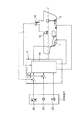
図1は、本発明に係るウォータジェット推進船の自動定点保持装置を示す構成図、図2は、図1のウォータジェット推進船を示す平面図、図3は、図1の自動定点保持装置の方位保持モードを示すブロック図、図4は、図3の自動定点保持装置の方位保持モードを示すフローチャート、図5は、図1の自動定点保持装置の位置保持モードを示すブロック図、図6は、図5の自動定点保持装置の位置保持モードを示すフローチャートである。 1 is a block diagram showing an automatic fixed point holding device for a water jet propulsion ship according to the present invention, FIG. 2 is a plan view showing the water jet propulsion ship of FIG. 1, and FIG. 3 is a block diagram of the automatic fixed point holding device of FIG. FIG. 4 is a flowchart showing the orientation holding mode of the automatic fixed point holding device of FIG. 3, FIG. 5 is a block diagram showing the position holding mode of the automatic fixed point holding device of FIG. 1, and FIG. FIG. 6 is a flowchart showing a position holding mode of the automatic fixed point holding apparatus of FIG. 5.
図1に示すように、本ウォータジェット推進船の自動定点保持装置は、ウォータジェット推進船の通常操船時の移動、回頭等を制御する自動操船装置の一部をなすものであり、符号1は、船体の船首尾方向の推力を、そのノズル角を変更させることにより方向可変に発生させることができるウォータジェット推進器であり、ウォータジェット推進器1は主機2を動力として推進力を発生させる。ウォータジェット推進器1及び主機2は、推進制御装置3からの制御指示により、機関制御装置4を介して、ウォータジェット推進器1のノズル角、主機2の回転数等が制御される。
As shown in FIG. 1, the automatic fixed point holding device of the water jet propulsion ship forms part of an automatic maneuvering apparatus that controls movement, turning, etc. of the water jet propulsion ship during normal maneuvering. This is a water jet propulsion device that can generate thrust in the stern direction of the hull in a variable direction by changing its nozzle angle. The water
一方、船首部には、サイドスラスタの一種であるバウスラスタ5が配設される。バウスラスタ5は、推進制御装置3からの制御指示により、スラスタ制御盤6を介してその回転数、翼角等が制御される。なお、サイドスラスタは、必ずしもバウスラスタ5に限定されるものではなく、スタンスラスタ等のサイドスラスタを備えるものでもよい。また、図2に示すように、ウォータジェット推進器1は、例えば2基から成り、バウスラスタ5は、例えば1基から成る。ウォータジェット推進器1は、横移動の場合等の力学的な面から、2基以上から成ることが望ましい。
On the other hand, a
図1に示すように、推進制御装置3には、ジャイロコンパス等の方位を検出する方位センサ10、電磁ログ,ドップラーログ等の船速を検出する船速センサ11、風向風速を検出する風向風速センサ12、GPS,DGPS等の船位を検出する船位センサ13等が接続される。また、推進制御装置3には、推進制御装置3への制御指示を行なうマスターコントローラ(制御盤)20、及び可搬式の遠隔操作箱(制御盤)21が接続される。このように、マスターコントローラ20のほか、可搬式の遠隔操作箱21を装備することにより、後述のウォータジェット推進船の方位保持、船位保持等を含む操船全体が、より容易になる。
As shown in FIG. 1, the
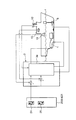
図3に示すように、マスターコントローラ20及び遠隔操作箱21には、船体の移動方向及び推力の設定が可能なジョイスティックレバー22、船体の回頭角速度の設定が可能な回頭ダイアル23、方位の設定が可能な方位設定ボタン24がそれぞれ配設され、図5に示すように、船位の設定が可能な船位設定ボタン25がそれぞれ配設される。
As shown in FIG. 3, the
船体の移動方向は、ジョイスティックレバー22の傾倒方向で与えられ、船体の移動速度は、ジョイスティックレバー22の傾倒角度に比例して与えられる。また、ジョイスティックレパー22を中立にしたまま回頭ダイヤル23を回動させることによって、設定された回頭角速度を保持しながら、その場回頭を行うことができる。回頭ダイヤル23の回動方向は、船の回頭方向に相当し、回頭ダイヤル23の回動の大きさは、回頭角速度に比例する。このように、ジョイスティックレバー22及び回頭ダイアル23を備えることにより、ウォータジェット推進船の、高速での操船性のみならず、特に低速での操船性が一段と高められる。
The moving direction of the hull is given by the tilting direction of the
推進制御装置3は、ジョイスティックレバー22の傾倒方向や傾倒角度、及び回頭ダイヤル23の回動方向や回動角度に応じて、舶舶の移動、回頭、方位の変更等に必要な制御値を演算する。この演算された制御値に基づいて、ウォータジェット推進器1の推力及びノズル角と、バウスラスタ5の推力とが、図1に示す機関制御装置4及びスラスタ制御盤6に指示される。
The
船体の方位保持モードについて、図3及び図4を参照して説明する。図3に示すように、方位保持モードにおいては、ジャイロコンパス等の方位センサ10が検出した方位と、風向風速センサ12が検出した風向風速が、推進制御装置3へそれぞれ入力される。図4の方位保持モードルーチンに示すように、図3に示す制御盤20又は遠隔操作箱21のジョイスティックレバー22及び回頭ダイヤル23を中立位置にする(ステップS2)。図3に示す方位設定ボタン24により、保持したい方位を設定する(ステップS4)。推進制御装置3の制御演算部3aが、方位センサ10が検出した方位と、風向風速センサ12が検出した風向風速を読み込む(ステップS6)。
The orientation holding mode of the hull will be described with reference to FIGS. As shown in FIG. 3, in the azimuth maintaining mode, the azimuth detected by the
推進制御装置3の制御演算部3aは、設定方位と、検出方位と、風向風速とに基づいて、図1に示す機関制御装置4に対し、ウォータジェット推進器1の推力及びノズル角を指示すると共に、図1に示すスラスタ制御盤6に対し、バウスラスタ5のスラスタ回転数を指示する(ステップS8)。検出方位及び回頭角速度のフィードバックをそれぞれ行なうと共に、検出方位が設定方位になっているか否かを判定する(ステップS10)。ステップS10の判定結果が否定(No)の場合、すなわち、検出方位が設定方位になっていない場合には、上述のステップS6〜S10を繰り返す。ステップS10の判定結果が肯定(Yes)の場合、すなわち、検出方位が設定方位になっている場合には、本方位保持モードルーチンを終了する。
The
船体の位置保持モードについて、図5及び図6を参照して説明する。図5に示すように、位置保持モードにおいては、ジャイロコンパス等の方位センサ10が検出した方位と、風向風速センサ12が検出した風向風速と、GPS,DGPS等の船位センサ13が検出した船位が、推進制御装置3へそれぞれ入力される。図5の位置保持モードルーチンに示すように、図5に示すマスターコントローラ20又は遠隔操作箱21の方位設定ボタン24により方位を設定し、船位設定ボタン25により船位を設定する(ステップS20)。方位センサ10が検出した方位と、風向風速センサ12が検出した風向風速と、船位センサ13が検出した船位を読み込む(ステップS22)。
The hull position holding mode will be described with reference to FIGS. As shown in FIG. 5, in the position holding mode, the azimuth detected by the
推進制御装置3の制御演算部3aは、設定方位と、検出方位と、設定船位と、検出船位と、風向風速とに基づいて、図1に示す機関制御装置4に対し、ウォータジェット推進器1の推力及びノズル角を指示すると共に、図1に示すスラスタ制御盤6に対し、バウスラスタ5のスラスタ回転数を指示する(ステップS24)。検出方位と検出船位のフィードバックを行うと共に、検出方位及び検出船位がそれぞれ設定方位及び設定船位になっているか否かを判定する(ステップS26)。ステップS26の判定結果が否定の場合、すなわち、検出方位及び検出船位がそれぞれ設定方位及び設定船位になっていない場合には、上述のステップS22〜S26を繰り返す。ステップS26の判定結果が肯定の場合、すなわち、検出方位及び検出船位がそれぞれ設定方位及び設定船位になっている場合には、本位置保持モードルーチンを終了する。
The
このように、本ウォータジェット推進船の自動定点保持装置によれば、推進制御装置3がウォータジェット推進器1の推力及びノズル角と、バウスラスタ5の推力とを、検出した方位と船位と風向風速に応じて適切に変化させることにより、ウォータジェット推進船の方位保持及び船位保持を自動的に行うことができ、これにより、従来は主に高速操船に適していたウォータジェット推進船を、離着桟操船や海洋調査観測時の低速操船にも適したものとすることができ、ウォータジェット推進船の利用範囲を格段に広げることができる。
As described above, according to the automatic fixed point holding device of the water jet propulsion ship, the
なお、上述のウォータジェット推進船の自動定点保持装置は、一例にすぎず、本発明の趣旨に基づいて種々の変形が可能であり、それらを本発明の範囲から排除するものではない。 The above-mentioned automatic fixed point holding device for a water jet propulsion ship is merely an example, and various modifications can be made based on the gist of the present invention, and they are not excluded from the scope of the present invention.
1 ウォータジェット推進器
2 主機
3 推進制御装置
3a 制御演算部
4 機関制御装置
5 バウスラスタ
6 スラスタ制御盤
10 方位センサ
11 船速センサ
12 風向風速センサ
13 船位センサ
20 マスターコントローラ
21 遠隔操作箱
22 ジョイスティックレバー
23 回頭ダイアル
24 方位設定ボタン
25 船位設定ボタン
DESCRIPTION OF
Claims (5)
Priority Applications (1)
| Application Number | Priority Date | Filing Date | Title |
|---|---|---|---|
| JP2004068657A JP4295645B2 (en) | 2004-03-11 | 2004-03-11 | Automatic fixed point holding device for water jet propulsion ship |
Applications Claiming Priority (1)
| Application Number | Priority Date | Filing Date | Title |
|---|---|---|---|
| JP2004068657A JP4295645B2 (en) | 2004-03-11 | 2004-03-11 | Automatic fixed point holding device for water jet propulsion ship |
Publications (3)
| Publication Number | Publication Date |
|---|---|
| JP2005254956A JP2005254956A (en) | 2005-09-22 |
| JP2005254956A5 JP2005254956A5 (en) | 2006-05-25 |
| JP4295645B2 true JP4295645B2 (en) | 2009-07-15 |
Family
ID=35081119
Family Applications (1)
| Application Number | Title | Priority Date | Filing Date |
|---|---|---|---|
| JP2004068657A Expired - Lifetime JP4295645B2 (en) | 2004-03-11 | 2004-03-11 | Automatic fixed point holding device for water jet propulsion ship |
Country Status (1)
| Country | Link |
|---|---|
| JP (1) | JP4295645B2 (en) |
Families Citing this family (9)
| Publication number | Priority date | Publication date | Assignee | Title |
|---|---|---|---|---|
| KR100702171B1 (en) | 2006-03-16 | 2007-03-30 | 주식회사 삼원기업 | Auto pilot method for a water jet propulsion system and it's system |
| JP5200010B2 (en) * | 2006-06-02 | 2013-05-15 | シーダブリューエフ ハミルトン アンド カンパニー リミテッド | Improvements in marine vessel control |
| JP5481059B2 (en) * | 2008-11-28 | 2014-04-23 | ヤマハ発動機株式会社 | Maneuvering support apparatus and ship equipped with the same |
| KR101210919B1 (en) | 2010-09-06 | 2012-12-11 | 대우조선해양 주식회사 | Position Holding System and Method for floating Structure with Lock Part |
| JP5970363B2 (en) * | 2011-12-15 | 2016-08-17 | 川崎重工業株式会社 | Crane ship and arithmetic control device for controlling crane ship |
| JP5956233B2 (en) * | 2012-04-25 | 2016-07-27 | Jmuディフェンスシステムズ株式会社 | Route holding control device and ship |
| JP6421111B2 (en) * | 2015-12-11 | 2018-11-07 | ヤンマー株式会社 | Maneuvering equipment |
| ES2655485B1 (en) * | 2016-08-19 | 2018-12-11 | Enrico MAIOZZI | Electronic anchoring system with geostationary control |
| KR102416756B1 (en) * | 2020-12-01 | 2022-07-06 | 김윤철 | Ship's hull stabilization device |
Family Cites Families (9)
| Publication number | Priority date | Publication date | Assignee | Title |
|---|---|---|---|---|
| JPH0684160B2 (en) * | 1988-11-04 | 1994-10-26 | 川崎重工業株式会社 | Ship handling equipment |
| JP2882930B2 (en) * | 1992-02-17 | 1999-04-19 | 川崎重工業株式会社 | Ship control equipment |
| JP2926531B2 (en) * | 1993-12-15 | 1999-07-28 | 三井造船株式会社 | Automatic position holding device |
| JPH0858696A (en) * | 1994-08-18 | 1996-03-05 | Mitsui Eng & Shipbuild Co Ltd | Automatic ship position holding system for twin-screw ship |
| JP2961594B2 (en) * | 1995-01-18 | 1999-10-12 | 三井造船株式会社 | Ship route control method and apparatus |
| JP3057413B2 (en) * | 1995-02-13 | 2000-06-26 | 三井造船株式会社 | Automatic ship maneuvering equipment |
| JP2808531B2 (en) * | 1995-04-17 | 1998-10-08 | 三菱重工業株式会社 | Aircraft control thrust distribution device |
| JP2788216B2 (en) * | 1995-12-08 | 1998-08-20 | 川崎重工業株式会社 | Control device for marine water jet propulsion |
| JPH10226395A (en) * | 1997-02-17 | 1998-08-25 | Nissan Motor Co Ltd | Position control device for ship |
-
2004
- 2004-03-11 JP JP2004068657A patent/JP4295645B2/en not_active Expired - Lifetime
Also Published As
| Publication number | Publication date |
|---|---|
| JP2005254956A (en) | 2005-09-22 |
Similar Documents
| Publication | Publication Date | Title |
|---|---|---|
| US7305928B2 (en) | Method for positioning a marine vessel | |
| US7267068B2 (en) | Method for maneuvering a marine vessel in response to a manually operable control device | |
| KR101409627B1 (en) | Improvements relating to control of marine vessels | |
| EP1981757B1 (en) | A method and arrangement for controlling a drive arrangement in a watercraft | |
| TWI443046B (en) | Ship, in particular a cargo ship having a magnus rotor | |
| EP3170735B1 (en) | Boat maneuvering control method for boat and boat maneuvering control system for boat | |
| US11597488B2 (en) | Ship maneuvering system, ship, and ship maneuvering method | |
| JP2017052297A (en) | Vessel maneuvering gear | |
| US10331137B2 (en) | Thruster system for marine vessels | |
| WO2018008589A1 (en) | Ship maneuvering system, ship, and ship maneuvering method | |
| JP4295645B2 (en) | Automatic fixed point holding device for water jet propulsion ship | |
| JP6421111B2 (en) | Maneuvering equipment | |
| JP2022179145A (en) | Ship propulsion control system and ship | |
| US20080269968A1 (en) | Watercraft position management system & method | |
| JP6521527B2 (en) | Ship steering apparatus and ship equipped with the same | |
| JPH08192794A (en) | Sea route holding control method and device of ship | |
| WO2019069382A1 (en) | Manoeuvring assistance device | |
| KR20130125252A (en) | Autonomous navigation system of floating marine structure having thruster and method thereof | |
| US20220382281A1 (en) | Marine vessel propulsion control system and marine vessel | |
| JP2002234494A (en) | Automatic ship steering device | |
| JP2926531B2 (en) | Automatic position holding device | |
| JP2001334995A (en) | Steering device | |
| WO2023171658A1 (en) | Ship, ship control device, ship control method, and program | |
| JP7145542B1 (en) | Steering system with steering angle correction function for single shaft and two rudder ships | |
| JP2001334996A (en) | Steering device |
Legal Events
| Date | Code | Title | Description |
|---|---|---|---|
| A621 | Written request for application examination |
Free format text: JAPANESE INTERMEDIATE CODE: A621 Effective date: 20060322 |
|
| A521 | Written amendment |
Free format text: JAPANESE INTERMEDIATE CODE: A523 Effective date: 20060331 |
|
| A977 | Report on retrieval |
Free format text: JAPANESE INTERMEDIATE CODE: A971007 Effective date: 20080821 |
|
| A131 | Notification of reasons for refusal |
Free format text: JAPANESE INTERMEDIATE CODE: A131 Effective date: 20080930 |
|
| A521 | Written amendment |
Free format text: JAPANESE INTERMEDIATE CODE: A523 Effective date: 20081126 |
|
| A131 | Notification of reasons for refusal |
Free format text: JAPANESE INTERMEDIATE CODE: A131 Effective date: 20090120 |
|
| A521 | Written amendment |
Free format text: JAPANESE INTERMEDIATE CODE: A523 Effective date: 20090217 |
|
| TRDD | Decision of grant or rejection written | ||
| A01 | Written decision to grant a patent or to grant a registration (utility model) |
Free format text: JAPANESE INTERMEDIATE CODE: A01 Effective date: 20090324 |
|
| A01 | Written decision to grant a patent or to grant a registration (utility model) |
Free format text: JAPANESE INTERMEDIATE CODE: A01 |
|
| A61 | First payment of annual fees (during grant procedure) |
Free format text: JAPANESE INTERMEDIATE CODE: A61 Effective date: 20090410 |
|
| FPAY | Renewal fee payment (event date is renewal date of database) |
Free format text: PAYMENT UNTIL: 20120417 Year of fee payment: 3 |
|
| R150 | Certificate of patent or registration of utility model |
Ref document number: 4295645 Country of ref document: JP Free format text: JAPANESE INTERMEDIATE CODE: R150 Free format text: JAPANESE INTERMEDIATE CODE: R150 |
|
| FPAY | Renewal fee payment (event date is renewal date of database) |
Free format text: PAYMENT UNTIL: 20130417 Year of fee payment: 4 |
|
| FPAY | Renewal fee payment (event date is renewal date of database) |
Free format text: PAYMENT UNTIL: 20140417 Year of fee payment: 5 |
|
| S111 | Request for change of ownership or part of ownership |
Free format text: JAPANESE INTERMEDIATE CODE: R313111 |
|
| S533 | Written request for registration of change of name |
Free format text: JAPANESE INTERMEDIATE CODE: R313533 |
|
| R350 | Written notification of registration of transfer |
Free format text: JAPANESE INTERMEDIATE CODE: R350 |
|
| R250 | Receipt of annual fees |
Free format text: JAPANESE INTERMEDIATE CODE: R250 |