EP0777632B1 - Kombinierter propeller für wasser aufbereitende vorrichtungen - Google Patents
Kombinierter propeller für wasser aufbereitende vorrichtungen Download PDFInfo
- Publication number
- EP0777632B1 EP0777632B1 EP95928906A EP95928906A EP0777632B1 EP 0777632 B1 EP0777632 B1 EP 0777632B1 EP 95928906 A EP95928906 A EP 95928906A EP 95928906 A EP95928906 A EP 95928906A EP 0777632 B1 EP0777632 B1 EP 0777632B1
- Authority
- EP
- European Patent Office
- Prior art keywords
- screw
- end part
- blade
- shaft
- screw blade
- Prior art date
- Legal status (The legal status is an assumption and is not a legal conclusion. Google has not performed a legal analysis and makes no representation as to the accuracy of the status listed.)
- Expired - Lifetime
Links
- XLYOFNOQVPJJNP-UHFFFAOYSA-N water Substances O XLYOFNOQVPJJNP-UHFFFAOYSA-N 0.000 title claims abstract description 21
- 238000005276 aerator Methods 0.000 claims description 9
- 230000000694 effects Effects 0.000 description 4
- 238000009434 installation Methods 0.000 description 1
- 239000007788 liquid Substances 0.000 description 1
- 238000000746 purification Methods 0.000 description 1
Images


Classifications
-
- C—CHEMISTRY; METALLURGY
- C02—TREATMENT OF WATER, WASTE WATER, SEWAGE, OR SLUDGE
- C02F—TREATMENT OF WATER, WASTE WATER, SEWAGE, OR SLUDGE
- C02F3/00—Biological treatment of water, waste water, or sewage
- C02F3/02—Aerobic processes
- C02F3/12—Activated sludge processes
- C02F3/14—Activated sludge processes using surface aeration
- C02F3/16—Activated sludge processes using surface aeration the aerator having a vertical axis
- C02F3/165—Activated sludge processes using surface aeration the aerator having a vertical axis using vertical aeration channels
-
- B—PERFORMING OPERATIONS; TRANSPORTING
- B01—PHYSICAL OR CHEMICAL PROCESSES OR APPARATUS IN GENERAL
- B01F—MIXING, e.g. DISSOLVING, EMULSIFYING OR DISPERSING
- B01F27/00—Mixers with rotary stirring devices in fixed receptacles; Kneaders
- B01F27/05—Stirrers
- B01F27/11—Stirrers characterised by the configuration of the stirrers
- B01F27/114—Helically shaped stirrers, i.e. stirrers comprising a helically shaped band or helically shaped band sections
- B01F27/1143—Helically shaped stirrers, i.e. stirrers comprising a helically shaped band or helically shaped band sections screw-shaped, e.g. worms
-
- B—PERFORMING OPERATIONS; TRANSPORTING
- B01—PHYSICAL OR CHEMICAL PROCESSES OR APPARATUS IN GENERAL
- B01F—MIXING, e.g. DISSOLVING, EMULSIFYING OR DISPERSING
- B01F23/00—Mixing according to the phases to be mixed, e.g. dispersing or emulsifying
- B01F23/20—Mixing gases with liquids
- B01F23/23—Mixing gases with liquids by introducing gases into liquid media, e.g. for producing aerated liquids
- B01F23/234—Surface aerating
- B01F23/2342—Surface aerating with stirrers near to the liquid surface, e.g. partially immersed, for spraying the liquid in the gas or for sucking gas into the liquid, e.g. using stirrers rotating around a horizontal axis or using centrifugal force
- B01F23/23421—Surface aerating with stirrers near to the liquid surface, e.g. partially immersed, for spraying the liquid in the gas or for sucking gas into the liquid, e.g. using stirrers rotating around a horizontal axis or using centrifugal force the stirrers rotating about a vertical axis
- B01F23/234211—Stirrers thereof
-
- Y—GENERAL TAGGING OF NEW TECHNOLOGICAL DEVELOPMENTS; GENERAL TAGGING OF CROSS-SECTIONAL TECHNOLOGIES SPANNING OVER SEVERAL SECTIONS OF THE IPC; TECHNICAL SUBJECTS COVERED BY FORMER USPC CROSS-REFERENCE ART COLLECTIONS [XRACs] AND DIGESTS
- Y02—TECHNOLOGIES OR APPLICATIONS FOR MITIGATION OR ADAPTATION AGAINST CLIMATE CHANGE
- Y02W—CLIMATE CHANGE MITIGATION TECHNOLOGIES RELATED TO WASTEWATER TREATMENT OR WASTE MANAGEMENT
- Y02W10/00—Technologies for wastewater treatment
- Y02W10/10—Biological treatment of water, waste water, or sewage
Definitions
- This invention concerns a screw for apparatuses used for water purification installations, such as aerators or mixers, and more particularly for apparatuses of the type in which a source of power, which may or may not be mounted on a float, drives a shaft on which a screw (impeller device) is fitted.
- a source of power which may or may not be mounted on a float
- a screw impeller device
- aerators the water is sucked up, deflected and spread more or less horizontally over the surface of the water.
- mixers the water is sucked in and impelled down under the surface of the liquid.
- the state of the art impeller device (Belgian patent 884.216) consists of two parts, namely a lower part formed by a screw and an upper part formed by a paddle wheel.
- This embodiment was improved by the Belgian patent 893.687 by converting the screw and the paddle wheel to a single body in which the screw is gradually curved in the form of a spiral and merges into the paddles of the paddle wheel.
- a screw pump is formed, consisting of one single body in the form of a centrifugal screw propeller.
- This screw pump can serve either as an aerator or as a mixer, and can even be combined as a mixer/aerator as described in European patent 366.644.
- Such a screw pump can be single-stage (with one helicoidal, spiral-shaped screw blade) but can also be multistage (with several helicoidal, spiral-shaped screw blades. It is clear that a multistage screw involves more frictional losses and causes more turbulence in the flow of water sucked up or sucked in. A multistage pump also demands a greater capactity on the part of the power source. If a single-stage pump is used, the frictional losses and turbulence are reduced, and a power source with lower capacity is sufficient, but the water flow rate is also reduced.
- the aim of this invention is to offer a screw that combines the advantages of both the multistage and the single-stage pump, while avoiding the disadvantages of the multistage and single-stage pump.
- the screw has an upper end part and a lower end part, fitted round at least part of the shaft, driven by the power source.
- the screw comprises at least one continuous screw blade starting at said upper end part and continuing interruptedly until said lower end part and at least one discontinuous screw blade covering only part of the screw near at least one end part of the screw.
- the screw has two blades at the bottom, with one blade continuing through to the upper end part.
- the screw has two blades below, with one blade continuing to near the top end part, which in turn has two blades.
- the screw consists of a cylinder-shaped shaft driven by a motor, said shaft having on the motor side a more or less trumpet-shaped deflector body curving towards the outside.
- a screw with a helicoidal, spiral-shaped motion is mounted at least partly round this shaft.
- a good pump effect or impeller force is obtained when the outside diameter of said screw starts from zero near the lower end of the shaft and gradually increases.
- the screw can consist of one screw blade (single-stage) or of several screw blades (multistage), with the speed and the diameter in each case being either constant or variable.
- the form of the screw blades can be lightly curved upwards on the outside, thus increasing the pump effect.
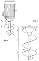
- Fig. 1 shows a surface aerator which can also be used as a mixer, consisting of a motor 1 which drives a shaft 2.
- Said shaft 2 broadens on the upper side, forming a deflecting body 6 which curves outward.
- Round the shaft 2 is mounted a screw 3.
- Said screw consists of a blade 4 which starts from the bottom of the shaft and, following a helicoidal, spiral-shaped motion, terminates in the deflecting body 6.
- a second screw blade 5 is also mounted at the bottom of the shaft; said second screw blade 5 however terminates after a spiral-shaped motion of approximately 180°.
- the screw therefore consists of two blades below, so achieving a good pump effect, but with one blade being very limited, so that little frictional losses and turbulence occur.
- Figs. 2 and 5 only show the screw around the shaft 2, where in Fig. 2 an upper end part A, a middle part B and a lower end part C can be distinguished.
- one screw blade 11 starts in the lower end part with a diameter varying from the shaft diameter to the full diameter, and continues with constant diameter into the deflecting body 6.
- An extra screw blade 12 is mounted in the lower end part C, also starting from the bottom of the shaft 2, but terminates after a spiral-shaped motion of 270° or so.
- Fig. 3 shows a variant of Fig. 2 with a continuous screw blade 11 and an extra screw blade 13 in the upper end part A.
- Fig. 4 shows a combination of Figs. 2 and 3, with a continuous screw blade 11 and an extra screw blade 12 in end part C and another extra screw blade 13 in end part A.
- the screws 11 and 13 terminate underneath the deflecting body 6, so that the upper end part A is situated lower.
- Fig. 5 shows a variant of Fig. 4, in which a continuous screw blade 21 has a constant diameter and starts below the shaft 2.
- a continuous screw blade 21 has a constant diameter and starts below the shaft 2.
- the discontinuous screw blades terminate after about 90°, 180°, 270° or 360°, but it is clear that there is no restriction on the execution of these screw blades, and that it can also terminate after one quarter of a revolution or can make any other fraction of a revolution or any number of revolutions. It is up to the person skilled in the art to determine which length a screw blade should have.
Landscapes
- Chemical & Material Sciences (AREA)
- Chemical Kinetics & Catalysis (AREA)
- Life Sciences & Earth Sciences (AREA)
- Biodiversity & Conservation Biology (AREA)
- Microbiology (AREA)
- Hydrology & Water Resources (AREA)
- Engineering & Computer Science (AREA)
- Environmental & Geological Engineering (AREA)
- Water Supply & Treatment (AREA)
- Organic Chemistry (AREA)
- Aeration Devices For Treatment Of Activated Polluted Sludge (AREA)
- Water Treatment By Electricity Or Magnetism (AREA)
- Mixers Of The Rotary Stirring Type (AREA)
- Excavating Of Shafts Or Tunnels (AREA)
- Extraction Or Liquid Replacement (AREA)
Claims (7)
- Vorrichtung zum Behandeln von Wasser, wie ein Durchlüfter oder Mixer, die eine Kraftquelle (1) umfaßt, die eine Welle (2) antreibt, die einen schraubenartigen, spiralförmigen Propeller (3) trägt, der einen oberen Endabschnitt und einen unteren Endabschnitt aufweist, und zumindest um einen Teil der Welle (2) herum befestigt ist, so daß Wasser nach oben gesaugt oder nach unten getrieben wird, dadurch gekennzeichnet, daß der Propeller zumindest ein durchgehendes Propellerblatt (4), das an dem oberen Endabschnitt beginnt und ohne Unterbrechung bis zu dem unteren Endabschnitt fortläuft, und zumindest ein unterbrochenes Propellerblatt (5) umfaßt, das nur einen Teil des Propellers in der Nähe von zumindest einem Endabschnitt des Propellers abdeckt.
- Vorrichtung zum Behandeln von Wasser nach Anspruch 1, dadurch gekennzeichnet, daß der Propeller ein durchgehendes Propellerblatt (11) und zumindest ein unterbrochenes Propellerblatt (12) an dem unteren Endabschnitt (C) umfaßt.
- Vorrichtung zum Behandeln von Wasser nach Anspruch 2, dadurch gekennzeichnet, daß der Propeller auch zumindest ein unterbrochenes Propellerblatt (13) an dem oberen Endabschnitt (A) umfaßt.
- Vorrichtung zum Behandeln von Wasser nach Anspruch 1, dadurch gekennzeichnet, daß der Propeller ein durchgehendes Propellerblatt (11) und zumindest ein unterbrochenes Propellerblatt (13) an dem oberen Endabschnitt (A) umfaßt.
- Vorrichtung zum Behandeln von Wasser nach Anspruch 1, dadurch gekennzeichnet, daß die Form der Propellerblätter an der Außenseite leicht nach oben gekrümmt ist.
- Oberflächenbelüfter, dadurch gekennzeichnet, daß er einen Propeller nach Anspruch 1 umfaßt.
- Wassermixer, dadurch gekennzeichnet, daß er einen Propeller nach Anspruch 1 umfaßt.
Applications Claiming Priority (3)
| Application Number | Priority Date | Filing Date | Title |
|---|---|---|---|
| BE9400765 | 1994-08-24 | ||
| BE9400765A BE1008654A3 (nl) | 1994-08-24 | 1994-08-24 | Gecombineerde schroef voor waterbehandelingsapparaten. |
| PCT/BE1995/000077 WO1996006050A1 (en) | 1994-08-24 | 1995-08-23 | Combined screw for water processing apparatuses |
Publications (2)
| Publication Number | Publication Date |
|---|---|
| EP0777632A1 EP0777632A1 (de) | 1997-06-11 |
| EP0777632B1 true EP0777632B1 (de) | 1999-03-31 |
Family
ID=3888315
Family Applications (1)
| Application Number | Title | Priority Date | Filing Date |
|---|---|---|---|
| EP95928906A Expired - Lifetime EP0777632B1 (de) | 1994-08-24 | 1995-08-23 | Kombinierter propeller für wasser aufbereitende vorrichtungen |
Country Status (7)
| Country | Link |
|---|---|
| US (1) | US5961212A (de) |
| EP (1) | EP0777632B1 (de) |
| AT (1) | ATE178290T1 (de) |
| AU (1) | AU3248795A (de) |
| BE (1) | BE1008654A3 (de) |
| DE (1) | DE69508768D1 (de) |
| WO (1) | WO1996006050A1 (de) |
Cited By (1)
| Publication number | Priority date | Publication date | Assignee | Title |
|---|---|---|---|---|
| CN108339452A (zh) * | 2018-03-08 | 2018-07-31 | 广州泰若智能化科技有限公司 | 一种改进型饮用水有机物的高级催化装置 |
Families Citing this family (9)
| Publication number | Priority date | Publication date | Assignee | Title |
|---|---|---|---|---|
| US6527520B2 (en) | 1999-07-29 | 2003-03-04 | Jonathan B. Rosefsky | Ribbon drive pumping with centrifugal contaminant removal |
| US6431926B1 (en) | 1999-07-29 | 2002-08-13 | Jonathan B. Rosefsky | Ribbon drive propulsion system and method |
| US7018170B2 (en) * | 1999-07-29 | 2006-03-28 | Rosefsky Jonathan B | Ribbon drive pumping apparatus and method with added fluid |
| KR100436206B1 (ko) * | 2000-11-06 | 2004-06-16 | 백 기 김 | 저수지 수질 개선 방법 |
| MXPA06003903A (es) * | 2003-10-10 | 2006-12-15 | Senju Metal Industry Co | Tanque de soldadura por onda. |
| DE102004033089A1 (de) * | 2004-07-08 | 2006-03-02 | Maschinenfabrik Kemper Gmbh & Co. Kg | Querförderschnecke für einen Erntevorsatz |
| JP4093586B1 (ja) * | 2007-02-23 | 2008-06-04 | 株式会社プラントコンストラクトアンドエンジニアリング | 物質移送装置 |
| CN102765823B (zh) * | 2012-07-20 | 2013-09-18 | 西安建筑科技大学 | 一种风力直驱循环充氧设备 |
| CN104499232A (zh) * | 2013-04-17 | 2015-04-08 | 勾昌羽 | 槽轮式匀水分配装置 |
Family Cites Families (18)
| Publication number | Priority date | Publication date | Assignee | Title |
|---|---|---|---|---|
| US1696994A (en) * | 1923-05-08 | 1929-01-01 | Grellet Collins | Mixing tank |
| US1524605A (en) * | 1923-11-15 | 1925-01-27 | Grellet Collins | Apparatus for treating paper stock |
| US3076637A (en) * | 1959-01-30 | 1963-02-05 | Monsanto Chemicals | Continuous blender for thermoplastic materials |
| US3323570A (en) * | 1964-05-27 | 1967-06-06 | Tullock Nigral Ray | Plastic ingredients mixing and grinding attachment |
| US3421740A (en) * | 1966-10-31 | 1969-01-14 | Norman A Behrens | Material mixer |
| US3856272A (en) * | 1972-06-08 | 1974-12-24 | Richards Of Rockford Inc | Floating mixer |
| SU424724A1 (ru) * | 1972-06-14 | 1974-04-25 | горноснасательного дела | Устройство для приготовления суспензий |
| US4123226A (en) * | 1977-01-26 | 1978-10-31 | Phillips Petroleum Company | Method employing a mixing device with internal recycle |
| US4202636A (en) * | 1977-01-26 | 1980-05-13 | Phillips Petroleum Company | Mixing device with internal recycle |
| AT352986B (de) * | 1977-03-09 | 1979-10-25 | Mathis Fertigputz | Vorrichtung zur herstellung von angemachtem moertel od.dgl. |
| AU520034B2 (en) * | 1977-05-26 | 1982-01-14 | Globe Roof Tile Machines Pty. Ltd. | Mixing apparatus |
| IT1113348B (it) * | 1979-05-09 | 1986-01-20 | Giza Spa | Fermentatore per liquani zootecnici |
| SU909315A2 (ru) * | 1980-01-28 | 1982-02-28 | Всесоюзный Научно-Исследовательский Конструкторско-Технологический Институт По Машинам Для Комплексной Механизации И Автоматизации Животноводческих Ферм | Вертикальный насос |
| FR2489293A1 (fr) * | 1980-09-04 | 1982-03-05 | Bruneau Noel | Utilisation d'une helice double sur les appareils de traitement des eaux |
| FR2491158A1 (fr) * | 1980-09-30 | 1982-04-02 | Minerva Oil | Pompe de transvasement d'un produit visqueux tel que de la graisse |
| GB8416863D0 (en) * | 1984-07-03 | 1984-08-08 | Witcombe J D | Cement mixer |
| IT1175874B (it) * | 1984-10-19 | 1987-07-15 | Caple & Montanari Spa | Autoclave per il trattamento di liquore di cacao |
| BE1002575A5 (nl) * | 1988-10-26 | 1991-03-26 | Haegeman J H | Menger en/of beluchter voor afvalwater. |
-
1994
- 1994-08-24 BE BE9400765A patent/BE1008654A3/nl not_active IP Right Cessation
-
1995
- 1995-08-23 EP EP95928906A patent/EP0777632B1/de not_active Expired - Lifetime
- 1995-08-23 DE DE69508768T patent/DE69508768D1/de not_active Expired - Lifetime
- 1995-08-23 WO PCT/BE1995/000077 patent/WO1996006050A1/en not_active Ceased
- 1995-08-23 US US08/793,366 patent/US5961212A/en not_active Expired - Fee Related
- 1995-08-23 AT AT95928906T patent/ATE178290T1/de active
- 1995-08-23 AU AU32487/95A patent/AU3248795A/en not_active Abandoned
Cited By (1)
| Publication number | Priority date | Publication date | Assignee | Title |
|---|---|---|---|---|
| CN108339452A (zh) * | 2018-03-08 | 2018-07-31 | 广州泰若智能化科技有限公司 | 一种改进型饮用水有机物的高级催化装置 |
Also Published As
| Publication number | Publication date |
|---|---|
| DE69508768D1 (de) | 1999-05-06 |
| BE1008654A3 (nl) | 1996-07-02 |
| WO1996006050A1 (en) | 1996-02-29 |
| ATE178290T1 (de) | 1999-04-15 |
| US5961212A (en) | 1999-10-05 |
| EP0777632A1 (de) | 1997-06-11 |
| AU3248795A (en) | 1996-03-14 |
Similar Documents
| Publication | Publication Date | Title |
|---|---|---|
| US4468358A (en) | Apparatus for mixing air and liquid | |
| EP0777632B1 (de) | Kombinierter propeller für wasser aufbereitende vorrichtungen | |
| US4540528A (en) | Apparatus for mixing gas and liquid | |
| EP0026493B1 (de) | Apparat zum in Kontakt Bringen einer Flüssigkeit mit einem Gas | |
| EP1023220A1 (de) | Belüftungsverfahren und -gerät mit verwendung eines impellers mit flexiblen flügeln | |
| US4917577A (en) | High speed centrifugal oxygenator | |
| US2072944A (en) | Aerator | |
| JP2001501702A (ja) | 養魚場用の低ヘッドポンプ装置 | |
| US2063301A (en) | Aerator | |
| EP2395245A3 (de) | Wasserpumpe mit variablem Durchfluss | |
| JP2947087B2 (ja) | 先行待機形ポンプの振動防止装置 | |
| WO1996015706A1 (en) | Food processor | |
| JP2002239587A (ja) | 深水の溶存酸素増強装置 | |
| JPS60101B2 (ja) | 水中に気泡を拡散させるポンプ装置 | |
| EP0612696B1 (de) | Verfahren und Vorrichtung zur kontrollierten Bewegung von Wasser in Wasserbecken | |
| ES2006285A6 (es) | Bomba centrifuga. | |
| US4145289A (en) | Aeration and filtration pump for aquariums | |
| WO1996009989A1 (en) | Aerator with improved efficiency | |
| JP2000000594A (ja) | 遠心通気装置 | |
| CN1442047A (zh) | 旋转扬水曝气机 | |
| JPH07217600A (ja) | ポンプ装置 | |
| JP3348226B2 (ja) | ドレン排水ポンプ | |
| JPH047274B2 (de) | ||
| JP3239172B2 (ja) | 攪拌曝気装置における軸流インペラおよび攪拌曝気装置の運転方法 | |
| KR100298007B1 (ko) | 미세기포 발생장치 |
Legal Events
| Date | Code | Title | Description |
|---|---|---|---|
| PUAI | Public reference made under article 153(3) epc to a published international application that has entered the european phase |
Free format text: ORIGINAL CODE: 0009012 |
|
| 17P | Request for examination filed |
Effective date: 19970324 |
|
| AK | Designated contracting states |
Kind code of ref document: A1 Designated state(s): AT DE DK ES FR GB IE IT NL PT SE |
|
| 17Q | First examination report despatched |
Effective date: 19971215 |
|
| GRAG | Despatch of communication of intention to grant |
Free format text: ORIGINAL CODE: EPIDOS AGRA |
|
| RAP1 | Party data changed (applicant data changed or rights of an application transferred) |
Owner name: AQUASYSTEMS INTERNATIONAL N.V. |
|
| GRAG | Despatch of communication of intention to grant |
Free format text: ORIGINAL CODE: EPIDOS AGRA |
|
| GRAH | Despatch of communication of intention to grant a patent |
Free format text: ORIGINAL CODE: EPIDOS IGRA |
|
| GRAH | Despatch of communication of intention to grant a patent |
Free format text: ORIGINAL CODE: EPIDOS IGRA |
|
| GRAA | (expected) grant |
Free format text: ORIGINAL CODE: 0009210 |
|
| AK | Designated contracting states |
Kind code of ref document: B1 Designated state(s): AT DE DK ES FR GB IE IT NL PT SE |
|
| PG25 | Lapsed in a contracting state [announced via postgrant information from national office to epo] |
Ref country code: SE Free format text: THE PATENT HAS BEEN ANNULLED BY A DECISION OF A NATIONAL AUTHORITY Effective date: 19990331 Ref country code: NL Free format text: LAPSE BECAUSE OF FAILURE TO SUBMIT A TRANSLATION OF THE DESCRIPTION OR TO PAY THE FEE WITHIN THE PRESCRIBED TIME-LIMIT Effective date: 19990331 Ref country code: IT Free format text: LAPSE BECAUSE OF FAILURE TO SUBMIT A TRANSLATION OF THE DESCRIPTION OR TO PAY THE FEE WITHIN THE PRESCRIBED TIME-LIMIT;WARNING: LAPSES OF ITALIAN PATENTS WITH EFFECTIVE DATE BEFORE 2007 MAY HAVE OCCURRED AT ANY TIME BEFORE 2007. THE CORRECT EFFECTIVE DATE MAY BE DIFFERENT FROM THE ONE RECORDED. Effective date: 19990331 Ref country code: FR Free format text: LAPSE BECAUSE OF FAILURE TO SUBMIT A TRANSLATION OF THE DESCRIPTION OR TO PAY THE FEE WITHIN THE PRESCRIBED TIME-LIMIT Effective date: 19990331 Ref country code: ES Free format text: THE PATENT HAS BEEN ANNULLED BY A DECISION OF A NATIONAL AUTHORITY Effective date: 19990331 Ref country code: AT Free format text: LAPSE BECAUSE OF FAILURE TO SUBMIT A TRANSLATION OF THE DESCRIPTION OR TO PAY THE FEE WITHIN THE PRESCRIBED TIME-LIMIT Effective date: 19990331 |
|
| REF | Corresponds to: |
Ref document number: 178290 Country of ref document: AT Date of ref document: 19990415 Kind code of ref document: T |
|
| REG | Reference to a national code |
Ref country code: IE Ref legal event code: FG4D |
|
| REF | Corresponds to: |
Ref document number: 69508768 Country of ref document: DE Date of ref document: 19990506 |
|
| PG25 | Lapsed in a contracting state [announced via postgrant information from national office to epo] |
Ref country code: PT Free format text: LAPSE BECAUSE OF FAILURE TO SUBMIT A TRANSLATION OF THE DESCRIPTION OR TO PAY THE FEE WITHIN THE PRESCRIBED TIME-LIMIT Effective date: 19990630 Ref country code: DK Free format text: LAPSE BECAUSE OF FAILURE TO SUBMIT A TRANSLATION OF THE DESCRIPTION OR TO PAY THE FEE WITHIN THE PRESCRIBED TIME-LIMIT Effective date: 19990630 |
|
| PG25 | Lapsed in a contracting state [announced via postgrant information from national office to epo] |
Ref country code: DE Free format text: LAPSE BECAUSE OF FAILURE TO SUBMIT A TRANSLATION OF THE DESCRIPTION OR TO PAY THE FEE WITHIN THE PRESCRIBED TIME-LIMIT Effective date: 19990701 |
|
| PG25 | Lapsed in a contracting state [announced via postgrant information from national office to epo] |
Ref country code: IE Free format text: LAPSE BECAUSE OF NON-PAYMENT OF DUE FEES Effective date: 19990823 Ref country code: GB Free format text: LAPSE BECAUSE OF NON-PAYMENT OF DUE FEES Effective date: 19990823 |
|
| EN | Fr: translation not filed | ||
| NLV1 | Nl: lapsed or annulled due to failure to fulfill the requirements of art. 29p and 29m of the patents act | ||
| PLBE | No opposition filed within time limit |
Free format text: ORIGINAL CODE: 0009261 |
|
| STAA | Information on the status of an ep patent application or granted ep patent |
Free format text: STATUS: NO OPPOSITION FILED WITHIN TIME LIMIT |
|
| 26N | No opposition filed | ||
| GBPC | Gb: european patent ceased through non-payment of renewal fee |
Effective date: 19990823 |
|
| REG | Reference to a national code |
Ref country code: IE Ref legal event code: MM4A |