EP0777028A1 - An operator with at least two linkage mechanisms for opening and closing pivotal windows - Google Patents
An operator with at least two linkage mechanisms for opening and closing pivotal windows Download PDFInfo
- Publication number
- EP0777028A1 EP0777028A1 EP96610045A EP96610045A EP0777028A1 EP 0777028 A1 EP0777028 A1 EP 0777028A1 EP 96610045 A EP96610045 A EP 96610045A EP 96610045 A EP96610045 A EP 96610045A EP 0777028 A1 EP0777028 A1 EP 0777028A1
- Authority
- EP
- European Patent Office
- Prior art keywords
- linkage mechanisms
- operator
- housing
- common
- operator according
- Prior art date
- Legal status (The legal status is an assumption and is not a legal conclusion. Google has not performed a legal analysis and makes no representation as to the accuracy of the status listed.)
- Granted
Links
Images


Classifications
-
- E—FIXED CONSTRUCTIONS
- E05—LOCKS; KEYS; WINDOW OR DOOR FITTINGS; SAFES
- E05F—DEVICES FOR MOVING WINGS INTO OPEN OR CLOSED POSITION; CHECKS FOR WINGS; WING FITTINGS NOT OTHERWISE PROVIDED FOR, CONCERNED WITH THE FUNCTIONING OF THE WING
- E05F11/00—Man-operated mechanisms for operating wings, including those which also operate the fastening
- E05F11/02—Man-operated mechanisms for operating wings, including those which also operate the fastening for wings in general, e.g. fanlights
- E05F11/04—Man-operated mechanisms for operating wings, including those which also operate the fastening for wings in general, e.g. fanlights with cords, chains or cables
- E05F11/06—Man-operated mechanisms for operating wings, including those which also operate the fastening for wings in general, e.g. fanlights with cords, chains or cables in guide-channels
-
- E—FIXED CONSTRUCTIONS
- E05—LOCKS; KEYS; WINDOW OR DOOR FITTINGS; SAFES
- E05F—DEVICES FOR MOVING WINGS INTO OPEN OR CLOSED POSITION; CHECKS FOR WINGS; WING FITTINGS NOT OTHERWISE PROVIDED FOR, CONCERNED WITH THE FUNCTIONING OF THE WING
- E05F15/00—Power-operated mechanisms for wings
- E05F15/60—Power-operated mechanisms for wings using electrical actuators
- E05F15/603—Power-operated mechanisms for wings using electrical actuators using rotary electromotors
- E05F15/611—Power-operated mechanisms for wings using electrical actuators using rotary electromotors for swinging wings
- E05F15/616—Power-operated mechanisms for wings using electrical actuators using rotary electromotors for swinging wings operated by push-pull mechanisms
- E05F15/619—Power-operated mechanisms for wings using electrical actuators using rotary electromotors for swinging wings operated by push-pull mechanisms using flexible or rigid rack-and-pinion arrangements
-
- E—FIXED CONSTRUCTIONS
- E05—LOCKS; KEYS; WINDOW OR DOOR FITTINGS; SAFES
- E05Y—INDEXING SCHEME RELATING TO HINGES OR OTHER SUSPENSION DEVICES FOR DOORS, WINDOWS OR WINGS AND DEVICES FOR MOVING WINGS INTO OPEN OR CLOSED POSITION, CHECKS FOR WINGS AND WING FITTINGS NOT OTHERWISE PROVIDED FOR, CONCERNED WITH THE FUNCTIONING OF THE WING
- E05Y2201/00—Constructional elements; Accessories therefore
- E05Y2201/10—Covers; Housings
- E05Y2201/11—Covers
-
- E—FIXED CONSTRUCTIONS
- E05—LOCKS; KEYS; WINDOW OR DOOR FITTINGS; SAFES
- E05Y—INDEXING SCHEME RELATING TO HINGES OR OTHER SUSPENSION DEVICES FOR DOORS, WINDOWS OR WINGS AND DEVICES FOR MOVING WINGS INTO OPEN OR CLOSED POSITION, CHECKS FOR WINGS AND WING FITTINGS NOT OTHERWISE PROVIDED FOR, CONCERNED WITH THE FUNCTIONING OF THE WING
- E05Y2201/00—Constructional elements; Accessories therefore
- E05Y2201/60—Suspension or transmission members; Accessories therefore
- E05Y2201/622—Suspension or transmission members elements
- E05Y2201/644—Flexible elongated pulling elements; Members cooperating with flexible elongated pulling elements
- E05Y2201/656—Chains
-
- E—FIXED CONSTRUCTIONS
- E05—LOCKS; KEYS; WINDOW OR DOOR FITTINGS; SAFES
- E05Y—INDEXING SCHEME RELATING TO HINGES OR OTHER SUSPENSION DEVICES FOR DOORS, WINDOWS OR WINGS AND DEVICES FOR MOVING WINGS INTO OPEN OR CLOSED POSITION, CHECKS FOR WINGS AND WING FITTINGS NOT OTHERWISE PROVIDED FOR, CONCERNED WITH THE FUNCTIONING OF THE WING
- E05Y2201/00—Constructional elements; Accessories therefore
- E05Y2201/60—Suspension or transmission members; Accessories therefore
- E05Y2201/622—Suspension or transmission members elements
- E05Y2201/71—Toothed gearing
- E05Y2201/722—Racks
- E05Y2201/724—Flexible
-
- E—FIXED CONSTRUCTIONS
- E05—LOCKS; KEYS; WINDOW OR DOOR FITTINGS; SAFES
- E05Y—INDEXING SCHEME RELATING TO HINGES OR OTHER SUSPENSION DEVICES FOR DOORS, WINDOWS OR WINGS AND DEVICES FOR MOVING WINGS INTO OPEN OR CLOSED POSITION, CHECKS FOR WINGS AND WING FITTINGS NOT OTHERWISE PROVIDED FOR, CONCERNED WITH THE FUNCTIONING OF THE WING
- E05Y2600/00—Mounting or coupling arrangements for elements provided for in this subclass
- E05Y2600/40—Mounting location; Visibility of the elements
-
- E—FIXED CONSTRUCTIONS
- E05—LOCKS; KEYS; WINDOW OR DOOR FITTINGS; SAFES
- E05Y—INDEXING SCHEME RELATING TO HINGES OR OTHER SUSPENSION DEVICES FOR DOORS, WINDOWS OR WINGS AND DEVICES FOR MOVING WINGS INTO OPEN OR CLOSED POSITION, CHECKS FOR WINGS AND WING FITTINGS NOT OTHERWISE PROVIDED FOR, CONCERNED WITH THE FUNCTIONING OF THE WING
- E05Y2800/00—Details, accessories and auxiliary operations not otherwise provided for
- E05Y2800/20—Combinations of elements
- E05Y2800/21—Combinations of elements of identical elements, e.g. of identical compression springs
-
- E—FIXED CONSTRUCTIONS
- E05—LOCKS; KEYS; WINDOW OR DOOR FITTINGS; SAFES
- E05Y—INDEXING SCHEME RELATING TO HINGES OR OTHER SUSPENSION DEVICES FOR DOORS, WINDOWS OR WINGS AND DEVICES FOR MOVING WINGS INTO OPEN OR CLOSED POSITION, CHECKS FOR WINGS AND WING FITTINGS NOT OTHERWISE PROVIDED FOR, CONCERNED WITH THE FUNCTIONING OF THE WING
- E05Y2800/00—Details, accessories and auxiliary operations not otherwise provided for
- E05Y2800/72—Sets of mutually exchangeable elements
-
- E—FIXED CONSTRUCTIONS
- E05—LOCKS; KEYS; WINDOW OR DOOR FITTINGS; SAFES
- E05Y—INDEXING SCHEME RELATING TO HINGES OR OTHER SUSPENSION DEVICES FOR DOORS, WINDOWS OR WINGS AND DEVICES FOR MOVING WINGS INTO OPEN OR CLOSED POSITION, CHECKS FOR WINGS AND WING FITTINGS NOT OTHERWISE PROVIDED FOR, CONCERNED WITH THE FUNCTIONING OF THE WING
- E05Y2900/00—Application of doors, windows, wings or fittings thereof
- E05Y2900/10—Application of doors, windows, wings or fittings thereof for buildings or parts thereof
- E05Y2900/13—Application of doors, windows, wings or fittings thereof for buildings or parts thereof characterised by the type of wing
- E05Y2900/148—Windows
Definitions
- the present invention relates to an operator for opening and closing pivotal windows between a closed position and a ventilation position and of the type comprising at least two pull and pressure transferring, flexible linkage mechanisms, which each at one end is connected with a fixture mounted on a frame or main frame member which is in parallel with the pivotal axis of the window and which at the opposite end comprises a part which is in engagement with a driving device mounted on the opposite main frame or frame member, said driving device being common to the linkage mechanisms, which are arranged mutually spaced in the longitudinal direction of said main frame or frame member.
- Window operators of this type typically comprise chain operators with a single operator chain, like for instance known from DK patent application No. 4104/89 and US Patent No. 4,532,993.
- This known arrangement is as to its mechanical construction comparatively complicated, which makes installation troublesome, and on account of the wall brackets extending below the windows in question, it is less appealing from an aesthetic point of view.
- the object of the invention is to provide an operator of the type in question for use in connection with bigger single windows of considerable weight or for preventing influence from wind on windows having a big pane area and for operating windows positioned side by side, said operator having a simple, compact construction with a design acceptable from an aesthetic point of view and being easy to mount, also when installed on existing windows.
- an operator of the type in question is according to the invention characteristic in that the driving device and the parts of the linkage mechanisms in engagement therewith are mounted in a common, substantially closed housing for accommodating the total length of the linkage mechanisms and provided with guide means, and, in a common side wall of the housing, lead-in openings for the linkage mechanisms, a carrier member positioned in connection with said guide means via transmission elements in the housing being connected with a common driving unit.
- the linkage mechanisms of the operator according to the invention will typically be chains, for instance of the same type as described in the above US Patent No. 1,333,595, but may also be other kinds of flexible linkage mechanisms, for instance profiled steel spring belts of the type described in DE published specification No. 4407276.
- a double chain operator according to the invention is shown, said chain operator being mounted between a bottom frame member 1 and a bottom main frame member 2, the free ends of the two operator chains 3 and 4 being fastened, possibly detachably, to the frame bottom member 1 by means of mounting fixtures 5,6, whereas the chains as such are received in a common housing 7 which is mounted on the bottom main frame member 2.
- the housing 7 is provided with guide means in form of stationary grooves 8 and 9 for receiving the parts of the operator chains 3 and 4 positioned in the housing.
- a carrier element is provided, in the embodiment shown sprocket wheels 10 and 11, which each via a worm transmission 12, 13 and a drive shaft half 14, 15 is connected with a gear transmission 16, which is connected to an electric drive motor 17.
- the grooves 8 and 9 lead to lead-in openings 8a and 9a in a side wall 7a of the housing 7.
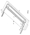
- the operator chains 3 and 4 are in a conventional way composed by chain links 18 which are connected by means of rivets or pins 19.
- the chains 3 and 4 are, as is known per se from US Patent No. 1,333,595, designed such that they are substantially only flexible in a plane perpendicular to the axis of rotation of the chain joints, i.e. in parallel with the frame members and the main frame members 1, 2, but they show considerable rigidity against bending forces perpendicular to this plane.
- the active parts of the operator chains 3 and 4 will, as shown in Fig. 1, thus take up a pronounced rectilinear course.
- the housing 7 is preferably connected in such a way to the bottom main frame member 2 that relative thereto it is pivotal around an axis parallel with the longitudinal direction of the housing, such that it may follow the linkage movement of the operator chains 3 and 4.
- the grooves 8 and 9 are separate for each theirs of the operator chains 3 and 4, and the carrier elements 10, 11 in form of sprocket wheels are placed in connection with each theirs of the grooves 8 and 9.
- the operator may be designed such that, with a view to producing an auxiliary force for the opening movement of the window, an energy storing takes place during the closing movement, where the closing force is produced by the weight of the window, until the pressure therefrom is surmounted by sealing pressure from the sealing positioned between the frame and the main frame.
- Such an energy storing may be produced by tightening a suitable spring load, in the embodiment shown for instance in form of torsion springs 14a and 15a surrounding the shaft half 14 and 15 and being connected to a shaft half and the housing 7 or to roller springs arranged around the shafts of the sprocket wheels 10 and 11, respectively.
- a suitable spring load in the embodiment shown for instance in form of torsion springs 14a and 15a surrounding the shaft half 14 and 15 and being connected to a shaft half and the housing 7 or to roller springs arranged around the shafts of the sprocket wheels 10 and 11, respectively.
- the two operator chains 20 and 21 may on a part of their length, counted from the end opposite the mounting fixtures, be mutually connected and led in a common groove 22, such that the two chains 20 and 21 may be driven by means of a single carrier element in form of a sprocket wheel 23.
- the operator chains 20 and 21 are led in each their separate groove 24 and 25, respectively, to lead-in openings 24a and 25a.
- the driving mechanism as shown in Fig. 5 may be simplified, the sprocket wheel 23 being directly connectable with the drive motor 26 with accompanying gear transmission.
- the driving device may also as shown in Fig. 7 be designed in another way, for instance by comprising a nut member 51 connected with the coupled lengths of the operator chains 20a and 21a in connection with a screw spindle 52 extending in parallel with the common groove 22a and being via a transmission 53 connected with the drive motor 54.
- the operator may be designed for energy storing during the closing movement as described above, for instance by mounting, along the common groove 22, for instance below it, a tension spring, one end of which is fastened to the ends of the coupled parts of the chains 20 and 21 and the other end being fastened in the housing, for instance at the transition between the common groove 22 and the separate grooves 24 and 25.
- the housing 28 in two parts with connectable housing parts 28a and 28b with a common dividing plane 29 perpendicular to the longitudinal direction of the grooves, advantageously to vary the total length of the operator housing 28 by coupling between the two housing parts 28a and 28b, as shown in Fig. 5, a separate insertion piece 30 which may be of variable length, simultaneously with a corresponding increase of the length of the chains 20 and 21.
- the housing parts 28a and 28b may be provided with engagement means in form of guide pins 31, 32 or the like.
- the operator chains 33 and 34 are received in compartments 35 which are mutually connected through a rail 36 and each holds not shown guide means and carrier elements in form of sprocket wheels and via the drive shaft halves 37 and 38 are in integral connection with a gear transmission 39 coupled with an electric drive motor 40 in such a way that these parts constitute a complete operator unit 41.
- This integrated operator unit 41 is floatingly mounted in a housing 42 with a predetermined clear, preferably 3-4 mm relative to the inside faces of its walls.
- the operator unit 41 with the full length of the chains 33 and 34 received in the compartments 35 may be introduced into the housing 42 from one end after the fastening of the housing on a frame or main frame member, the end walls 43 and 44 of the housing being detachable.
- the floating mounting of the operator unit 41 in the housing 2 makes it possible to compensate for irregularities, if any, at the mounting of the housing 42 and to advantageously reduce the risk of skew pulling the window.
- Such a risk of skew pulling may, in embodiments where the driving device and the guide means and carrier elements for the chains are stationary relative to the housing, arise due to the fact that the frame and main frame construction of the window work, for instance as a consequence of varying moist absorption. Thereby skewness may result between frame and main frame, following which the two operator chains at the closing of the window pull the frame askew towards the main frame, which may partly result in leaks between the frame and the main frame, and partly result, in part of the construction, in an overloading of a sealing positioned between the frame and the main frame.
- the weight of the window frame will in its open position cause the operator unit 41 into abutment against the side wall 45 (facing away from the window frame) of the housing 42.
- the operator unit 41 acts in this phase in practice solely as collector of the chains 33 and 34.
- a springy element in connection with the operator unit 41 may be mounted between the operator unit 41 and the side wall 46, for instance as shown a compound spring 47, which is designed for abutment against the side wall 46 and comprises an activating part for a switch for the motor current.
- the compound spring 47 may, as shown, at one end part be provided with a curved portion 47a for abutment against the side wall 46 and at its free end be fastened to the connection rail 36 of the operator unit 41.
- the second end portion of the compound spring 47 is designed as a substantially rectilinear portion 47b, which by compressive stress of the curved portion 47a is displaced in the longitudinal direction of the rail 36, whereby its free end 47c may actuate a micro switch 48 mounted on the rail 36 and serving as a switch for the motor current.
- the curved portion 47a of the compound spring 47 which is in abutment against the housing wall 46, will be exposed to compressive stress and become deformed, when the operator unit 41, when the sealing pressure has started to exceed the pressure from the weight of the frame, moves in a direction towards the wall 46.
- the operator unit 41 will then turn around a rotational axis 49 determined by the point of contact between the curved portion 47a of the compound spring and the wall 46 as indicated by the double arrow 50, whereby any skewness will be equalized.
- the compound spring 47 is dimensioned with such a length and spring characteristic that the micro switch 48 will not be activated until the skewness, if any, has been equalized and the desired sealing pressure established.
- micro switch 48 is mounted in such a way on the operator unit 41 that its contact element in itself forms a point of contact between the operator unit 41 and the housing wall 46, the switch having to be subjected to a spring bias which may resist the forces during the equalization of skewness, if any, but still disconnecting the motor current when the desired sealing pressure has been established in the whole sealing between frame and main frame.
Abstract
Description
- The present invention relates to an operator for opening and closing pivotal windows between a closed position and a ventilation position and of the type comprising at least two pull and pressure transferring, flexible linkage mechanisms, which each at one end is connected with a fixture mounted on a frame or main frame member which is in parallel with the pivotal axis of the window and which at the opposite end comprises a part which is in engagement with a driving device mounted on the opposite main frame or frame member, said driving device being common to the linkage mechanisms, which are arranged mutually spaced in the longitudinal direction of said main frame or frame member.
- Window operators of this type typically comprise chain operators with a single operator chain, like for instance known from DK patent application No. 4104/89 and US Patent No. 4,532,993.
- From US Patent No. 1,333,595 it is for simultaneous opening and closing of several windows positioned side by side known to provide a chain operator of the type in question with a corresponding number of operator chains which each at one end is fastened to a common operation rod which is movable forwards and backwards with a channel-shaped cross-section which constitutes a guide groove for the chain lengths running at any time along the rod. The operation rod may be manually operated or motor driven, and its movement is controlled by comparatively space demanding guide rollers journalled in wall-mounted brackets below the windows to be operated by means of the operator mechanism.
- This known arrangement is as to its mechanical construction comparatively complicated, which makes installation troublesome, and on account of the wall brackets extending below the windows in question, it is less appealing from an aesthetic point of view.
- In view of this prior art the object of the invention is to provide an operator of the type in question for use in connection with bigger single windows of considerable weight or for preventing influence from wind on windows having a big pane area and for operating windows positioned side by side, said operator having a simple, compact construction with a design acceptable from an aesthetic point of view and being easy to mount, also when installed on existing windows.
- To meet this object an operator of the type in question is according to the invention characteristic in that the driving device and the parts of the linkage mechanisms in engagement therewith are mounted in a common, substantially closed housing for accommodating the total length of the linkage mechanisms and provided with guide means, and, in a common side wall of the housing, lead-in openings for the linkage mechanisms, a carrier member positioned in connection with said guide means via transmission elements in the housing being connected with a common driving unit.
- The linkage mechanisms of the operator according to the invention will typically be chains, for instance of the same type as described in the above US Patent No. 1,333,595, but may also be other kinds of flexible linkage mechanisms, for instance profiled steel spring belts of the type described in DE published specification No. 4407276.
- By mounting both the driving device and the parts of the linkage mechanisms in engagement therewith in a common housing, which is substantially closed, i.e. which is substantially only in a common side wall provided with openings for the linkage mechanisms at the mouth of the grooves, in which they are received, a design which is appealing from an aesthetic point of view is obtained together with a substantially reduced risk of soiling the mechanism.
- Accomodation of the linkage mechanisms in grooves provided for that purpose in the housing and without the linkage mechanisms being anchored therein entails a precise guiding of the linkage mechanisms contrary to the embodiment known from US Patent No. 1,333,595, which embodiment requires a very high degree of precision when placing the chain fastenings along the common operation rod.
- Advantageous embodiments of the invention and further developed embodiments thereof appear from the dependent claims.
- The invention will be described in detail in the following with reference to the schematic drawing, in which
- Fig. 1 shows a part of a top-hung window provided with an embodiment of a chain operator according to the invention,
- Fig. 2 shows the operator housing with chain grooves and driving device according to the embodiment of Fig. 1,
- Fig. 3 shows the mechanic transmission between a driving device and the operator chains according to the embodiment of Figs. 1 and 2,
- Fig. 4 shows the chain groove according to another embodiment of the operator housing,
- Fig. 5 shows a further developed embodiment of the embodiment shown in Fig. 4,
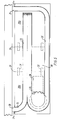
- Fig. 6 shows a further embodiment designed to prevent a skew pull when closing a window, and
- Fig. 7 is a modification of the embodiments shown in Figs. 4 and 5.
- In Fig. 1, and in respect of a top-hung window, an embodiment of a double chain operator according to the invention is shown, said chain operator being mounted between a bottom frame member 1 and a bottom
main frame member 2, the free ends of the twooperator chains fixtures common housing 7 which is mounted on the bottommain frame member 2. - As shown in Figs. 2 and 3, the
housing 7 is provided with guide means in form of stationary grooves 8 and 9 for receiving the parts of theoperator chains grooves 8 and 9 a carrier element is provided, in the embodiment shownsprocket wheels 10 and 11, which each via aworm transmission drive shaft half gear transmission 16, which is connected to an electric drive motor 17. The grooves 8 and 9 lead to lead-inopenings 8a and 9a in a side wall 7a of thehousing 7. - The
operator chains chain links 18 which are connected by means of rivets orpins 19. In the embodiment shown thechains main frame members 1, 2, but they show considerable rigidity against bending forces perpendicular to this plane. - Contrary to the operator chains in conventional chains operators of the type disclosed in US Patent No. 4,521,993, the active parts of the
operator chains operator housing 7 thereto, thehousing 7 is preferably connected in such a way to the bottommain frame member 2 that relative thereto it is pivotal around an axis parallel with the longitudinal direction of the housing, such that it may follow the linkage movement of theoperator chains - According to the embodiments of Figs. 1-3 the grooves 8 and 9 are separate for each theirs of the
operator chains carrier elements 10, 11 in form of sprocket wheels are placed in connection with each theirs of the grooves 8 and 9. - Particularly for use in connection with a sloping roof window the biggest energy requirement will occur during the opening movement, where the weight of the window frame is to be overcome solely by the pressure from the
chains - To reduce this energy requirement the operator may be designed such that, with a view to producing an auxiliary force for the opening movement of the window, an energy storing takes place during the closing movement, where the closing force is produced by the weight of the window, until the pressure therefrom is surmounted by sealing pressure from the sealing positioned between the frame and the main frame.
- Such an energy storing may be produced by tightening a suitable spring load, in the embodiment shown for instance in form of
torsion springs shaft half housing 7 or to roller springs arranged around the shafts of thesprocket wheels 10 and 11, respectively. - According to another embodiment shown in Fig. 4 the two
operator chains common groove 22, such that the twochains sprocket wheel 23. In extension of thecommon groove 22, theoperator chains separate groove openings - By this embodiment the driving mechanism as shown in Fig. 5 may be simplified, the
sprocket wheel 23 being directly connectable with thedrive motor 26 with accompanying gear transmission. - By this embodiment the driving device may also as shown in Fig. 7 be designed in another way, for instance by comprising a
nut member 51 connected with the coupled lengths of the operator chains 20a and 21a in connection with ascrew spindle 52 extending in parallel with the common groove 22a and being via atransmission 53 connected with thedrive motor 54. - Also in accordance with the embodiments in Figs. 4, 5, and 7 the operator may be designed for energy storing during the closing movement as described above, for instance by mounting, along the
common groove 22, for instance below it, a tension spring, one end of which is fastened to the ends of the coupled parts of thechains common groove 22 and theseparate grooves - By designing the embodiment shown in such a way that the common groove is rectilinear substantially through its entire length, and such that the
separate groove 25 for one of theoperator chains 21 likewise is rectilinear and in parallel with saidcommon groove 22, it becomes possible, by designing thehousing 28 in two parts withconnectable housing parts plane 29 perpendicular to the longitudinal direction of the grooves, advantageously to vary the total length of theoperator housing 28 by coupling between the twohousing parts chains - In view of a mutually secured positioning, the
housing parts guide pins - In the embodiment according to Fig. 6 the
operator chains compartments 35 which are mutually connected through arail 36 and each holds not shown guide means and carrier elements in form of sprocket wheels and via thedrive shaft halves gear transmission 39 coupled with anelectric drive motor 40 in such a way that these parts constitute acomplete operator unit 41. - This integrated
operator unit 41 is floatingly mounted in ahousing 42 with a predetermined clear, preferably 3-4 mm relative to the inside faces of its walls. - In this embodiment the
operator unit 41 with the full length of thechains compartments 35 may be introduced into thehousing 42 from one end after the fastening of the housing on a frame or main frame member, theend walls - In addition to simplifying the mounting work the floating mounting of the
operator unit 41 in thehousing 2 makes it possible to compensate for irregularities, if any, at the mounting of thehousing 42 and to advantageously reduce the risk of skew pulling the window. - Such a risk of skew pulling may, in embodiments where the driving device and the guide means and carrier elements for the chains are stationary relative to the housing, arise due to the fact that the frame and main frame construction of the window work, for instance as a consequence of varying moist absorption. Thereby skewness may result between frame and main frame, following which the two operator chains at the closing of the window pull the frame askew towards the main frame, which may partly result in leaks between the frame and the main frame, and partly result, in part of the construction, in an overloading of a sealing positioned between the frame and the main frame.
- By use of the embodiment according to Fig. 6 in connection with an inclined roof window, the weight of the window frame will in its open position cause the
operator unit 41 into abutment against the side wall 45 (facing away from the window frame) of thehousing 42. When closing the window it will alone be the weight of the frame which brings the frame towards the main frame. Theoperator unit 41 acts in this phase in practice solely as collector of thechains - Not until the frame has been brought into abutment against the sealing mounted on the main frame construction and the pressure therefrom exceeds the weight of the frame, will the
chains operator unit 41 tightens the frame towards the main frame, until the desired sealing pressure has been established, theoperator unit 41 moving on account of the floating mounting into abutment against the inner surface of theside wall 46 facing the frame of thehousing 42. - In order to control this displacement of the operator unit and to simultaneously ensure that the motor current to the
drive motor 40 is disconnected, as soon as the desired sealing pressure has been established, a springy element in connection with theoperator unit 41 may be mounted between theoperator unit 41 and theside wall 46, for instance as shown acompound spring 47, which is designed for abutment against theside wall 46 and comprises an activating part for a switch for the motor current. - The
compound spring 47 may, as shown, at one end part be provided with a curved portion 47a for abutment against theside wall 46 and at its free end be fastened to theconnection rail 36 of theoperator unit 41. The second end portion of thecompound spring 47 is designed as a substantially rectilinear portion 47b, which by compressive stress of the curved portion 47a is displaced in the longitudinal direction of therail 36, whereby its free end 47c may actuate amicro switch 48 mounted on therail 36 and serving as a switch for the motor current. - During closing of the window the curved portion 47a of the
compound spring 47, which is in abutment against thehousing wall 46, will be exposed to compressive stress and become deformed, when theoperator unit 41, when the sealing pressure has started to exceed the pressure from the weight of the frame, moves in a direction towards thewall 46. Theoperator unit 41 will then turn around arotational axis 49 determined by the point of contact between the curved portion 47a of the compound spring and thewall 46 as indicated by thedouble arrow 50, whereby any skewness will be equalized. - The
compound spring 47 is dimensioned with such a length and spring characteristic that themicro switch 48 will not be activated until the skewness, if any, has been equalized and the desired sealing pressure established. - Another possibility is to mount the
micro switch 48 in such a way on theoperator unit 41 that its contact element in itself forms a point of contact between theoperator unit 41 and thehousing wall 46, the switch having to be subjected to a spring bias which may resist the forces during the equalization of skewness, if any, but still disconnecting the motor current when the desired sealing pressure has been established in the whole sealing between frame and main frame.
Claims (16)
- An operator for opening and closing pivotal windows between a closed position and a ventilation position and of the type comprising at least two pull and pressure transferring, flexible linkage mechanisms (3,4; 20,21; 20a,21a; 33,34) which each at one end is connected with a fixture (5,6) mounted on a frame or main frame member which is in parallel with the pivotal axis of the window and which at the opposite end comprises a part which is in engagement with a driving device (12-17; 37-40; 52-54) mounted on the opposite main frame or frame member (2), said driving device being common to the linkage mechanisms, which are arranged mutually spaced in the longitudinal direction of said main frame or frame member (1,2), characterized in that the driving device (12-17; 26; 37-40; 52-54) and the parts of the linkage mechanisms (3,4; 20,21; 20a,21a; 33,34) in engagement therewith are mounted in a common, substantially closed housing (7; 28; 42) for accommodating the total length of the linkage mechanisms (3,4; 20,21; 20a,21a; 33,34) and provided with guide means (8,9; 22,22a,24,25), and, in a common side wall (7a; 46) of the housing, lead-in openings (8a,9a; 24a,25a) for the linkage mechanisms (3,4; 20,21; 20a,21a), a carrier member (10,11; 23; 51) positioned in connection with said guide means via transmission elements (12-16; 37-39; 52,57) in the housing (7,28; 42) being connected with a common driving unit (17,26,40,54).
- An operator according to claim 1, characterized in that the mounting fixtures (5,6) for the linkage mechanisms are placed on the same or each their frame member (1) for a single window or two neighbouring windows, respectively, and in that said housing (7,28,42) is mounted in connection with the main frame member/members (2) positioned oppositely.
- An operator according to claim 2, characterized in that the linkage mechanisms (3,4; 20,21; 33,34) are constructed such that they are flexible solely in a plane parallel with said frame and main frame members (1,2), but show considerable rigidity against bending forces perpendicularly to this plane, and that the housing (7,28,42) is connected with said main frame member (2) such that it is pivotable around an axis parallel with the longitudinal axis of the main frame member (2).
- An operator according to claim 2 or 3, characterized in that said guide means comprise grooves (8,9) leading to said lead-in openings (8a,9a), said grooves being separate for each theirs of the two linkage mechanisms (3,4), and that said carrier element (10,11) is positioned in connection with each of the grooves (8,9) for engagement with each of the linkage mechanisms (3,4) and connected via separate transmission elements (12,14; 13,15) with the common driving unit.
- An operator according to claim 2 or 3, characterized in that the two linkage mechanisms (20,21; 20a,21a) on a part of their length counted from the end opposite the mounting fixtures are mutually coupled and led in a common groove (22,22a), in connection with which a single carrier element (23, 51) acting on the coupled lengths of the linkage mechanisms (20,21; 20a,21a) is positioned.
- An operator according to claim 5, characterized in that said carrier element (23) is a drive wheel in engagement with one of the coupled linkage mechanisms (20,21) and connected with said transmission elements.
- An operator according to claim 5, characterized in that said carrier element (51) is a nut member connected with the coupled lengths of the linkage mechanisms (20a,21a) in connection with a screw spindle (52) extending in parallel with a rectilinear part of said common groove (22a).
- An operator according to claims 5, 6 or 7, characterized in that the entire length of the common groove (22,22a) is rectilinear, and that in parallel with said common groove (22,22a) in the housing (28) a likewise rectilinear section of a separate groove (25) for one of the linkage mechanisms (21) is provided, the housing (28) being designed in two parts by to a dividing plane (29) perpendicular to the longitudinal direction of said groove (22,25).
- An operator according to claim 8, characterized in that the two parts (28a,28b) of the housing (28) at said dividing plane (29) are provided with engagement means (31,32) for securing the mutual positioning of the two parts of the housing (28a,28b) in extension of each other.
- An operator according to claim 9, characterized in comprising an insertion piece (30) to be positioned between the two house parts for increasing the entire length of the housing.
- An operator according to any of the preceding claims, in particular for use in connection with an inclined roof window, characterized in comprising, with a view to producing an auxiliary force for the opening movement of the window, an element in the form of a spring member (14a,15a), which during the closing movement is energy-collecting, said element being mounted between the linkage mechanisms or a transmission element (14,15) and the common housing (7).
- An operator according to any of the preceding claims, characterized in that the driving device (40) together with said transmission elements (37-39) is designed as an operator unit (41) in integral connection with carrier elements in compartments (35) for receiving the linkage mechanisms, said operator unit (41) being floatingly mounted in the housing (42) with a predetermined clear relative to the inside faces of its walls.
- An operator according to claim 12, characterized in that a switch (48) for the motor current is connected with said operator unit (41) such that it switches off when, by displacement of the operator unit (41) in the housing in the direction towards said common side wall (46), a desired sealing pressure has been established, the switch (48) being affected by a springy member which allows equalization of misalignments, if any, before said switching off.
- An operator according to claim 13, characterized in that said springy member is constituted by a compound spring (47) which in an end part is provided with a curved portion (47a) for abutment against said shared side wall (46), the free end of said part being fastened to the operator unit (41), and the other end part being provided with a substantially rectilinear portion (47b), which is longitudinally displaceable by compressive stress on the curved portion (47a), and the free end of which forms an actuator for said switch (48).
- An operator according to any of the preceding claims, characterized in that the linkage mechanisms (3,4; 20,21; 20a,21a; 33,34) are chains.
- An operator according to claims 4 or 6 and 15, characterized in that said carrier element (10,11; 23) comprises sprocket wheels in engagement with one or both operator chains (3,4; 20,21).
Applications Claiming Priority (3)
| Application Number | Priority Date | Filing Date | Title |
|---|---|---|---|
| DK135995A DK135995A (en) | 1995-12-01 | 1995-12-01 | Operator with at least two display elements for opening and closing swivel windows |
| DK135995 | 1995-12-01 | ||
| DK1359/95 | 1995-12-01 |
Publications (2)
| Publication Number | Publication Date |
|---|---|
| EP0777028A1 true EP0777028A1 (en) | 1997-06-04 |
| EP0777028B1 EP0777028B1 (en) | 2001-05-30 |
Family
ID=8104000
Family Applications (1)
| Application Number | Title | Priority Date | Filing Date |
|---|---|---|---|
| EP96610045A Expired - Lifetime EP0777028B1 (en) | 1995-12-01 | 1996-11-25 | An operator with at least two linkage mechanisms for opening and closing pivotal windows |
Country Status (5)
| Country | Link |
|---|---|
| US (1) | US5896702A (en) |
| EP (1) | EP0777028B1 (en) |
| AT (1) | ATE201739T1 (en) |
| DE (1) | DE69613082T2 (en) |
| DK (2) | DK135995A (en) |
Cited By (11)
| Publication number | Priority date | Publication date | Assignee | Title |
|---|---|---|---|---|
| WO2000037760A1 (en) * | 1998-12-19 | 2000-06-29 | Ronald Percival Davis | A window opening and closing device |
| EP1353031A1 (en) * | 2002-04-09 | 2003-10-15 | VKR Holding A/S | Compact actuator |
| WO2005033455A1 (en) * | 2003-10-09 | 2005-04-14 | Vkr Holding A/S | Slim window actuator |
| WO2006074971A1 (en) * | 2005-01-15 | 2006-07-20 | SCHÜCO International KG | Drive device for a window or a door |
| EP1785570A2 (en) | 2005-11-10 | 2007-05-16 | TOPP S.p.A. | Chain-drive actuator assembly |
| FR2909407A1 (en) * | 2006-12-01 | 2008-06-06 | Window Automation Industry Srl | Electro-mechanical actuator for controlling i.e. window, has support with guide for interacting with chain, so that translation movement of support along longitudinal axes is obtained from driving of chain by pinion |
| EP1947279A2 (en) * | 2007-01-12 | 2008-07-23 | HAUTAU GmbH | End plug for the case of an actuating drive and device for fitting the case on a wing |
| DE202014001171U1 (en) * | 2014-02-11 | 2014-04-29 | Lock Antriebstechnik Gmbh | Adjusting device for a wing and device for setting multiple wings |
| CN108603568A (en) * | 2016-01-20 | 2018-09-28 | 伊维氏传动系统集团公司 | Actuator with back rigid link chain |
| WO2019016333A1 (en) * | 2017-07-20 | 2019-01-24 | Iwis Antriebssysteme Gmbh & Co. Kg | Linear drive with anti-back-bend chain |
| DE102022108095B3 (en) | 2022-04-05 | 2023-03-16 | Grob GmbH | linear chain |
Families Citing this family (16)
| Publication number | Priority date | Publication date | Assignee | Title |
|---|---|---|---|---|
| AU765285B2 (en) * | 1998-06-18 | 2003-09-11 | Assa Abloy Ip Ab | A multi-link connector |
| KR20030009981A (en) * | 2001-07-25 | 2003-02-05 | 황육익 | Windows operating system |
| CN101109255A (en) * | 2003-02-25 | 2008-01-23 | Vkr控股公司 | Barrier member for operator chain of chain operator |
| ITBO20070066A1 (en) * | 2007-02-01 | 2008-08-02 | Franceschi Daniele De | POLYFUNCTION LOCK AND ORGAN SERVOMOTOR ACTUATOR ROLLED ON INTERCHANGEABLE SPROCKET |
| US8074309B2 (en) * | 2009-03-04 | 2011-12-13 | Hill-Rom Services, Inc. | Height adjustable bed with a lift chain assembly and components thereof |
| AU2010100261B4 (en) * | 2009-12-18 | 2010-09-30 | Pacific Holdings (Aust) Pty Ltd | Improved chain |
| DE202010008488U1 (en) * | 2010-02-11 | 2011-06-09 | STG-Beikirch Industrieelektronik + Sicherheitstechnik GmbH & Co. KG, 32657 | Device for adjusting movement objects |
| US8104120B2 (en) * | 2010-02-18 | 2012-01-31 | Hill-Rom Services, Inc. | Height adjustable bed with a push chain assembly |
| JP5435679B2 (en) * | 2010-05-31 | 2014-03-05 | 独立行政法人産業技術総合研究所 | Linear motion telescopic arm mechanism and robot arm equipped with the linear motion telescopic arm mechanism |
| AU2011204857B2 (en) * | 2010-07-19 | 2016-06-30 | Azuma Design Pty Limited | A chain winder |
| US9737149B2 (en) * | 2010-09-10 | 2017-08-22 | Hill-Rom Services, Inc. | Height adjustable bed framework with a lift chain and a planetary gear train |
| SG11201610345UA (en) * | 2014-06-13 | 2017-01-27 | Ysl Surveyors Ltd | A retaining device for a window and a method for retaining a window |
| US10704314B2 (en) * | 2015-04-14 | 2020-07-07 | Wilmar Valverde | Automatic safety window apparatus and system |
| US9970517B2 (en) * | 2015-07-28 | 2018-05-15 | Northrop Grumman Systems Corporation | Satellite boom hinge actuator using drive chain with flexible and rigid characteristics |
| GB2553589A (en) * | 2016-09-13 | 2018-03-14 | Mighton Products Ltd | Limiter assembly for a window |
| DE102018104777A1 (en) * | 2018-03-02 | 2019-09-05 | Iwis Antriebssysteme Gmbh & Co. Kg | Actuator with back stiff chain |
Citations (9)
| Publication number | Priority date | Publication date | Assignee | Title |
|---|---|---|---|---|
| US1333595A (en) | 1917-02-09 | 1920-03-16 | G Drouve Company | Window-operating mechanism |
| US4235117A (en) * | 1978-12-07 | 1980-11-25 | Ferro Manufacturing Corporation | Tailgate window regulator |
| US4521993A (en) | 1983-08-08 | 1985-06-11 | Truth Incorporated | Chain operator for a window |
| US4532993A (en) | 1983-09-07 | 1985-08-06 | Shell Oil Company | Selective steam foam soak oil recovery process |
| US4819495A (en) * | 1986-02-01 | 1989-04-11 | Hormann Kg Antriebs- Und Steuerungstechnik | Gear for converting a rotary into a translational motion |
| DK410489A (en) | 1988-12-16 | 1990-06-17 | Truth Inc | OPERATION SYSTEM FOR OPENING AND CLOSING WINDOWS |
| US5156574A (en) * | 1990-11-06 | 1992-10-20 | Ultraflex S.R.L. | Power-assisted chain drive actuator for opening and closing gating fixtures |
| US5271182A (en) * | 1991-09-24 | 1993-12-21 | Aug.Winkhaus Gmbh & Co. Kg | Device for opening and closing the panel of a window, door, ventilation hatch, or similar closure |
| DE4407276A1 (en) | 1994-03-04 | 1995-09-07 | Geze Gmbh & Co | Window pane or ventilation flap adjustment device |
Family Cites Families (6)
| Publication number | Priority date | Publication date | Assignee | Title |
|---|---|---|---|---|
| US2017543A (en) * | 1933-10-16 | 1935-10-15 | George L Curtis | Supporting and adjusting hardware for sashes and the like |
| US4014136A (en) * | 1974-07-18 | 1977-03-29 | Teleflex Morse Limited | Means for the opening and closing of angularly movable panels |
| US4827668A (en) * | 1987-11-24 | 1989-05-09 | Bechtold Stephen K | Chain operator for a window |
| US4945678A (en) * | 1988-12-05 | 1990-08-07 | Truth Incorporated | Window operator |
| US5004961A (en) * | 1988-12-16 | 1991-04-02 | Truth Incorporated | Window operator control |
| US5406750A (en) * | 1993-05-12 | 1995-04-18 | V. Kann Rasmussen Industri A/S | Chain operator for windows |
-
1995
- 1995-12-01 DK DK135995A patent/DK135995A/en not_active Application Discontinuation
-
1996
- 1996-11-25 DK DK96610045T patent/DK0777028T3/en active
- 1996-11-25 EP EP96610045A patent/EP0777028B1/en not_active Expired - Lifetime
- 1996-11-25 DE DE69613082T patent/DE69613082T2/en not_active Expired - Lifetime
- 1996-11-25 AT AT96610045T patent/ATE201739T1/en active
- 1996-11-26 US US08/756,327 patent/US5896702A/en not_active Expired - Fee Related
Patent Citations (9)
| Publication number | Priority date | Publication date | Assignee | Title |
|---|---|---|---|---|
| US1333595A (en) | 1917-02-09 | 1920-03-16 | G Drouve Company | Window-operating mechanism |
| US4235117A (en) * | 1978-12-07 | 1980-11-25 | Ferro Manufacturing Corporation | Tailgate window regulator |
| US4521993A (en) | 1983-08-08 | 1985-06-11 | Truth Incorporated | Chain operator for a window |
| US4532993A (en) | 1983-09-07 | 1985-08-06 | Shell Oil Company | Selective steam foam soak oil recovery process |
| US4819495A (en) * | 1986-02-01 | 1989-04-11 | Hormann Kg Antriebs- Und Steuerungstechnik | Gear for converting a rotary into a translational motion |
| DK410489A (en) | 1988-12-16 | 1990-06-17 | Truth Inc | OPERATION SYSTEM FOR OPENING AND CLOSING WINDOWS |
| US5156574A (en) * | 1990-11-06 | 1992-10-20 | Ultraflex S.R.L. | Power-assisted chain drive actuator for opening and closing gating fixtures |
| US5271182A (en) * | 1991-09-24 | 1993-12-21 | Aug.Winkhaus Gmbh & Co. Kg | Device for opening and closing the panel of a window, door, ventilation hatch, or similar closure |
| DE4407276A1 (en) | 1994-03-04 | 1995-09-07 | Geze Gmbh & Co | Window pane or ventilation flap adjustment device |
Cited By (20)
| Publication number | Priority date | Publication date | Assignee | Title |
|---|---|---|---|---|
| WO2000037760A1 (en) * | 1998-12-19 | 2000-06-29 | Ronald Percival Davis | A window opening and closing device |
| AU754102B2 (en) * | 1998-12-19 | 2002-11-07 | Ronald Percival Davis | A window opening and closing device |
| EP1353031A1 (en) * | 2002-04-09 | 2003-10-15 | VKR Holding A/S | Compact actuator |
| WO2005033455A1 (en) * | 2003-10-09 | 2005-04-14 | Vkr Holding A/S | Slim window actuator |
| WO2006074971A1 (en) * | 2005-01-15 | 2006-07-20 | SCHÜCO International KG | Drive device for a window or a door |
| EP1785570A2 (en) | 2005-11-10 | 2007-05-16 | TOPP S.p.A. | Chain-drive actuator assembly |
| EP1785570A3 (en) * | 2005-11-10 | 2008-07-09 | TOPP S.p.A. | Chain-drive actuator assembly |
| FR2909407A1 (en) * | 2006-12-01 | 2008-06-06 | Window Automation Industry Srl | Electro-mechanical actuator for controlling i.e. window, has support with guide for interacting with chain, so that translation movement of support along longitudinal axes is obtained from driving of chain by pinion |
| WO2008071887A1 (en) * | 2006-12-01 | 2008-06-19 | Somfy Sas | Electromechanical actuator for maneuvering an opening and closing assembly including such actuator |
| US8468747B2 (en) | 2006-12-01 | 2013-06-25 | Somfy Sas | Electromechanical actuator for a closure and an assembly including the actuator and closure |
| EP1947279A3 (en) * | 2007-01-12 | 2008-09-17 | HAUTAU GmbH | End plug for the case of an actuating drive and device for fitting the case on a wing |
| EP2163717A1 (en) | 2007-01-12 | 2010-03-17 | HAUTAU GmbH | End plug for the case of an actuating drive and device for fitting the case on a wing |
| EP1947279A2 (en) * | 2007-01-12 | 2008-07-23 | HAUTAU GmbH | End plug for the case of an actuating drive and device for fitting the case on a wing |
| DE202014001171U1 (en) * | 2014-02-11 | 2014-04-29 | Lock Antriebstechnik Gmbh | Adjusting device for a wing and device for setting multiple wings |
| CN108603568A (en) * | 2016-01-20 | 2018-09-28 | 伊维氏传动系统集团公司 | Actuator with back rigid link chain |
| CN108603568B (en) * | 2016-01-20 | 2021-05-11 | 伊维氏传动系统集团公司 | Actuator with back rigid chain |
| WO2019016333A1 (en) * | 2017-07-20 | 2019-01-24 | Iwis Antriebssysteme Gmbh & Co. Kg | Linear drive with anti-back-bend chain |
| WO2019016340A1 (en) * | 2017-07-20 | 2019-01-24 | Iwis Antriebssysteme Gmbh & Co. Kg | Linear drive with rigid-spined chain |
| WO2019016337A1 (en) * | 2017-07-20 | 2019-01-24 | Iwis Antriebssysteme Gmbh & Co. Kg | Linear drive with rigid-spined chain |
| DE102022108095B3 (en) | 2022-04-05 | 2023-03-16 | Grob GmbH | linear chain |
Also Published As
| Publication number | Publication date |
|---|---|
| DK0777028T3 (en) | 2001-07-30 |
| ATE201739T1 (en) | 2001-06-15 |
| EP0777028B1 (en) | 2001-05-30 |
| US5896702A (en) | 1999-04-27 |
| DE69613082D1 (en) | 2001-07-05 |
| DE69613082T2 (en) | 2002-01-31 |
| DK135995A (en) | 1997-06-02 |
Similar Documents
| Publication | Publication Date | Title |
|---|---|---|
| EP0777028B1 (en) | An operator with at least two linkage mechanisms for opening and closing pivotal windows | |
| US7555867B2 (en) | Swing door operator | |
| EP1813757A1 (en) | Push-pull chain window actuator | |
| KR100533789B1 (en) | Electrically-driven Closure Apparatus For Building | |
| PL172286B1 (en) | Actuating system for opening/closing doors, windows, ventilation hatches and the like | |
| KR100687834B1 (en) | Panels of controllable radiation transmissivity | |
| KR100309022B1 (en) | Automotive Power Window Regulator | |
| CA2245812C (en) | Emergency opening device for a swinging folding door or a swinging folding gate | |
| US7445005B2 (en) | Household appliance and household appliance door | |
| JPS59145887A (en) | Motor driven type closure operation apparatus | |
| US7252082B2 (en) | Household appliance | |
| KR20090060963A (en) | Blinds for vehicles | |
| EP1353031B1 (en) | Compact actuator | |
| US5406750A (en) | Chain operator for windows | |
| CN114981516A (en) | Door operator system | |
| EP1673515A1 (en) | Slim window actuator | |
| KR930002107Y1 (en) | Electric drive device for opening and closing curtain | |
| KR100252595B1 (en) | An opening and closing device for auto-door | |
| JP3709280B2 (en) | Shutter for building | |
| EP0943774B1 (en) | Actuator with adjustable stroke | |
| KR101031097B1 (en) | Device for controlling tension using for automatic door | |
| KR0139201Y1 (en) | Control apparatus of wire tension of a vertical automatic blind | |
| US20230044431A1 (en) | Door operator system | |
| KR0158035B1 (en) | Sheet shutter | |
| RU2162417C2 (en) | Two-point window regulator |
Legal Events
| Date | Code | Title | Description |
|---|---|---|---|
| PUAI | Public reference made under article 153(3) epc to a published international application that has entered the european phase |
Free format text: ORIGINAL CODE: 0009012 |
|
| AK | Designated contracting states |
Kind code of ref document: A1 Designated state(s): AT BE CH DE DK ES FI FR GB GR IE IT LI LU MC NL PT SE |
|
| AX | Request for extension of the european patent |
Free format text: AL PAYMENT 961210;LT PAYMENT 961210;LV PAYMENT 961210;RO PAYMENT 961210;SI PAYMENT 961210 |
|
| 17P | Request for examination filed |
Effective date: 19971111 |
|
| RAP1 | Party data changed (applicant data changed or rights of an application transferred) |
Owner name: VELUX INDUSTRI A/S |
|
| 17Q | First examination report despatched |
Effective date: 19990622 |
|
| GRAG | Despatch of communication of intention to grant |
Free format text: ORIGINAL CODE: EPIDOS AGRA |
|
| GRAG | Despatch of communication of intention to grant |
Free format text: ORIGINAL CODE: EPIDOS AGRA |
|
| GRAH | Despatch of communication of intention to grant a patent |
Free format text: ORIGINAL CODE: EPIDOS IGRA |
|
| GRAH | Despatch of communication of intention to grant a patent |
Free format text: ORIGINAL CODE: EPIDOS IGRA |
|
| GRAA | (expected) grant |
Free format text: ORIGINAL CODE: 0009210 |
|
| RAP1 | Party data changed (applicant data changed or rights of an application transferred) |
Owner name: VKR HOLDING A/S |
|
| AK | Designated contracting states |
Kind code of ref document: B1 Designated state(s): AT BE CH DE DK ES FI FR GB GR IE IT LI LU MC NL PT SE |
|
| AX | Request for extension of the european patent |
Free format text: AL PAYMENT 19961210;LT PAYMENT 19961210;LV PAYMENT 19961210;RO PAYMENT 19961210;SI PAYMENT 19961210 |
|
| LTIE | Lt: invalidation of european patent or patent extension | ||
| PG25 | Lapsed in a contracting state [announced via postgrant information from national office to epo] |
Ref country code: NL Free format text: LAPSE BECAUSE OF FAILURE TO SUBMIT A TRANSLATION OF THE DESCRIPTION OR TO PAY THE FEE WITHIN THE PRESCRIBED TIME-LIMIT Effective date: 20010530 Ref country code: FI Free format text: LAPSE BECAUSE OF FAILURE TO SUBMIT A TRANSLATION OF THE DESCRIPTION OR TO PAY THE FEE WITHIN THE PRESCRIBED TIME-LIMIT Effective date: 20010530 Ref country code: BE Free format text: LAPSE BECAUSE OF FAILURE TO SUBMIT A TRANSLATION OF THE DESCRIPTION OR TO PAY THE FEE WITHIN THE PRESCRIBED TIME-LIMIT Effective date: 20010530 |
|
| REF | Corresponds to: |
Ref document number: 201739 Country of ref document: AT Date of ref document: 20010615 Kind code of ref document: T |
|
| REG | Reference to a national code |
Ref country code: CH Ref legal event code: EP |
|
| REF | Corresponds to: |
Ref document number: 69613082 Country of ref document: DE Date of ref document: 20010705 |
|
| REG | Reference to a national code |
Ref country code: IE Ref legal event code: FG4D |
|
| REG | Reference to a national code |
Ref country code: DK Ref legal event code: T3 |
|
| ITF | It: translation for a ep patent filed |
Owner name: ING. A. GIAMBROCONO & C. S.R.L. |
|
| PG25 | Lapsed in a contracting state [announced via postgrant information from national office to epo] |
Ref country code: SE Free format text: LAPSE BECAUSE OF FAILURE TO SUBMIT A TRANSLATION OF THE DESCRIPTION OR TO PAY THE FEE WITHIN THE PRESCRIBED TIME-LIMIT Effective date: 20010830 Ref country code: PT Free format text: LAPSE BECAUSE OF FAILURE TO SUBMIT A TRANSLATION OF THE DESCRIPTION OR TO PAY THE FEE WITHIN THE PRESCRIBED TIME-LIMIT Effective date: 20010830 |
|
| PG25 | Lapsed in a contracting state [announced via postgrant information from national office to epo] |
Ref country code: GR Free format text: LAPSE BECAUSE OF FAILURE TO SUBMIT A TRANSLATION OF THE DESCRIPTION OR TO PAY THE FEE WITHIN THE PRESCRIBED TIME-LIMIT Effective date: 20010831 |
|
| REG | Reference to a national code |
Ref country code: CH Ref legal event code: NV Representative=s name: TROESCH SCHEIDEGGER WERNER AG |
|
| ET | Fr: translation filed | ||
| NLV1 | Nl: lapsed or annulled due to failure to fulfill the requirements of art. 29p and 29m of the patents act | ||
| PG25 | Lapsed in a contracting state [announced via postgrant information from national office to epo] |
Ref country code: MC Free format text: LAPSE BECAUSE OF NON-PAYMENT OF DUE FEES Effective date: 20011125 Ref country code: LU Free format text: LAPSE BECAUSE OF NON-PAYMENT OF DUE FEES Effective date: 20011125 |
|
| PG25 | Lapsed in a contracting state [announced via postgrant information from national office to epo] |
Ref country code: IE Free format text: LAPSE BECAUSE OF FAILURE TO SUBMIT A TRANSLATION OF THE DESCRIPTION OR TO PAY THE FEE WITHIN THE PRESCRIBED TIME-LIMIT Effective date: 20011126 |
|
| PG25 | Lapsed in a contracting state [announced via postgrant information from national office to epo] |
Ref country code: ES Free format text: LAPSE BECAUSE OF FAILURE TO SUBMIT A TRANSLATION OF THE DESCRIPTION OR TO PAY THE FEE WITHIN THE PRESCRIBED TIME-LIMIT Effective date: 20011130 |
|
| REG | Reference to a national code |
Ref country code: GB Ref legal event code: IF02 |
|
| PLBE | No opposition filed within time limit |
Free format text: ORIGINAL CODE: 0009261 |
|
| STAA | Information on the status of an ep patent application or granted ep patent |
Free format text: STATUS: NO OPPOSITION FILED WITHIN TIME LIMIT |
|
| 26N | No opposition filed | ||
| REG | Reference to a national code |
Ref country code: IE Ref legal event code: MM4A |
|
| REG | Reference to a national code |
Ref country code: CH Ref legal event code: PFA Owner name: VKR HOLDING A/S Free format text: VKR HOLDING A/S#TOBAKSVEJEN 10#2860 SOEBORG (DK) -TRANSFER TO- VKR HOLDING A/S#BREELTEVEJ 18#2970 HOERSHOLM (DK) |
|
| PGFP | Annual fee paid to national office [announced via postgrant information from national office to epo] |
Ref country code: DK Payment date: 20081118 Year of fee payment: 13 |
|
| PGFP | Annual fee paid to national office [announced via postgrant information from national office to epo] |
Ref country code: GB Payment date: 20081117 Year of fee payment: 13 |
|
| REG | Reference to a national code |
Ref country code: DK Ref legal event code: EBP |
|
| GBPC | Gb: european patent ceased through non-payment of renewal fee |
Effective date: 20091125 |
|
| PG25 | Lapsed in a contracting state [announced via postgrant information from national office to epo] |
Ref country code: GB Free format text: LAPSE BECAUSE OF NON-PAYMENT OF DUE FEES Effective date: 20091125 |
|
| PG25 | Lapsed in a contracting state [announced via postgrant information from national office to epo] |
Ref country code: DK Free format text: LAPSE BECAUSE OF NON-PAYMENT OF DUE FEES Effective date: 20091130 |
|
| PGFP | Annual fee paid to national office [announced via postgrant information from national office to epo] |
Ref country code: CH Payment date: 20141112 Year of fee payment: 19 |
|
| PGFP | Annual fee paid to national office [announced via postgrant information from national office to epo] |
Ref country code: AT Payment date: 20141027 Year of fee payment: 19 |
|
| REG | Reference to a national code |
Ref country code: FR Ref legal event code: PLFP Year of fee payment: 20 |
|
| PGFP | Annual fee paid to national office [announced via postgrant information from national office to epo] |
Ref country code: IT Payment date: 20151124 Year of fee payment: 20 Ref country code: DE Payment date: 20151127 Year of fee payment: 20 |
|
| PGFP | Annual fee paid to national office [announced via postgrant information from national office to epo] |
Ref country code: FR Payment date: 20151117 Year of fee payment: 20 |
|
| REG | Reference to a national code |
Ref country code: CH Ref legal event code: PL |
|
| REG | Reference to a national code |
Ref country code: AT Ref legal event code: MM01 Ref document number: 201739 Country of ref document: AT Kind code of ref document: T Effective date: 20151125 |
|
| PG25 | Lapsed in a contracting state [announced via postgrant information from national office to epo] |
Ref country code: CH Free format text: LAPSE BECAUSE OF NON-PAYMENT OF DUE FEES Effective date: 20151130 Ref country code: LI Free format text: LAPSE BECAUSE OF NON-PAYMENT OF DUE FEES Effective date: 20151130 |
|
| PG25 | Lapsed in a contracting state [announced via postgrant information from national office to epo] |
Ref country code: AT Free format text: LAPSE BECAUSE OF NON-PAYMENT OF DUE FEES Effective date: 20151125 |
|
| REG | Reference to a national code |
Ref country code: DE Ref legal event code: R071 Ref document number: 69613082 Country of ref document: DE |