EP0776868B1 - Resistor for cathode ray tube and method of preparing same - Google Patents
Resistor for cathode ray tube and method of preparing same Download PDFInfo
- Publication number
- EP0776868B1 EP0776868B1 EP96119038A EP96119038A EP0776868B1 EP 0776868 B1 EP0776868 B1 EP 0776868B1 EP 96119038 A EP96119038 A EP 96119038A EP 96119038 A EP96119038 A EP 96119038A EP 0776868 B1 EP0776868 B1 EP 0776868B1
- Authority
- EP
- European Patent Office
- Prior art keywords
- resistance
- weight
- percent
- glass
- glass tube
- Prior art date
- Legal status (The legal status is an assumption and is not a legal conclusion. Google has not performed a legal analysis and makes no representation as to the accuracy of the status listed.)
- Expired - Lifetime
Links
Images


Classifications
-
- C—CHEMISTRY; METALLURGY
- C03—GLASS; MINERAL OR SLAG WOOL
- C03C—CHEMICAL COMPOSITION OF GLASSES, GLAZES OR VITREOUS ENAMELS; SURFACE TREATMENT OF GLASS; SURFACE TREATMENT OF FIBRES OR FILAMENTS MADE FROM GLASS, MINERALS OR SLAGS; JOINING GLASS TO GLASS OR OTHER MATERIALS
- C03C8/00—Enamels; Glazes; Fusion seal compositions being frit compositions having non-frit additions
- C03C8/14—Glass frit mixtures having non-frit additions, e.g. opacifiers, colorants, mill-additions
-
- C—CHEMISTRY; METALLURGY
- C03—GLASS; MINERAL OR SLAG WOOL
- C03C—CHEMICAL COMPOSITION OF GLASSES, GLAZES OR VITREOUS ENAMELS; SURFACE TREATMENT OF GLASS; SURFACE TREATMENT OF FIBRES OR FILAMENTS MADE FROM GLASS, MINERALS OR SLAGS; JOINING GLASS TO GLASS OR OTHER MATERIALS
- C03C17/00—Surface treatment of glass, not in the form of fibres or filaments, by coating
- C03C17/006—Surface treatment of glass, not in the form of fibres or filaments, by coating with materials of composite character
- C03C17/007—Surface treatment of glass, not in the form of fibres or filaments, by coating with materials of composite character containing a dispersed phase, e.g. particles, fibres or flakes, in a continuous phase
-
- C—CHEMISTRY; METALLURGY
- C03—GLASS; MINERAL OR SLAG WOOL
- C03C—CHEMICAL COMPOSITION OF GLASSES, GLAZES OR VITREOUS ENAMELS; SURFACE TREATMENT OF GLASS; SURFACE TREATMENT OF FIBRES OR FILAMENTS MADE FROM GLASS, MINERALS OR SLAGS; JOINING GLASS TO GLASS OR OTHER MATERIALS
- C03C3/00—Glass compositions
- C03C3/04—Glass compositions containing silica
- C03C3/062—Glass compositions containing silica with less than 40% silica by weight
- C03C3/07—Glass compositions containing silica with less than 40% silica by weight containing lead
- C03C3/072—Glass compositions containing silica with less than 40% silica by weight containing lead containing boron
- C03C3/074—Glass compositions containing silica with less than 40% silica by weight containing lead containing boron containing zinc
- C03C3/0745—Glass compositions containing silica with less than 40% silica by weight containing lead containing boron containing zinc containing more than 50% lead oxide, by weight
-
- C—CHEMISTRY; METALLURGY
- C03—GLASS; MINERAL OR SLAG WOOL
- C03C—CHEMICAL COMPOSITION OF GLASSES, GLAZES OR VITREOUS ENAMELS; SURFACE TREATMENT OF GLASS; SURFACE TREATMENT OF FIBRES OR FILAMENTS MADE FROM GLASS, MINERALS OR SLAGS; JOINING GLASS TO GLASS OR OTHER MATERIALS
- C03C3/00—Glass compositions
- C03C3/12—Silica-free oxide glass compositions
- C03C3/122—Silica-free oxide glass compositions containing oxides of As, Sb, Bi, Mo, W, V, Te as glass formers
-
- C—CHEMISTRY; METALLURGY
- C03—GLASS; MINERAL OR SLAG WOOL
- C03C—CHEMICAL COMPOSITION OF GLASSES, GLAZES OR VITREOUS ENAMELS; SURFACE TREATMENT OF GLASS; SURFACE TREATMENT OF FIBRES OR FILAMENTS MADE FROM GLASS, MINERALS OR SLAGS; JOINING GLASS TO GLASS OR OTHER MATERIALS
- C03C3/00—Glass compositions
- C03C3/12—Silica-free oxide glass compositions
- C03C3/16—Silica-free oxide glass compositions containing phosphorus
- C03C3/17—Silica-free oxide glass compositions containing phosphorus containing aluminium or beryllium
-
- C—CHEMISTRY; METALLURGY
- C03—GLASS; MINERAL OR SLAG WOOL
- C03C—CHEMICAL COMPOSITION OF GLASSES, GLAZES OR VITREOUS ENAMELS; SURFACE TREATMENT OF GLASS; SURFACE TREATMENT OF FIBRES OR FILAMENTS MADE FROM GLASS, MINERALS OR SLAGS; JOINING GLASS TO GLASS OR OTHER MATERIALS
- C03C8/00—Enamels; Glazes; Fusion seal compositions being frit compositions having non-frit additions
- C03C8/02—Frit compositions, i.e. in a powdered or comminuted form
- C03C8/04—Frit compositions, i.e. in a powdered or comminuted form containing zinc
-
- C—CHEMISTRY; METALLURGY
- C03—GLASS; MINERAL OR SLAG WOOL
- C03C—CHEMICAL COMPOSITION OF GLASSES, GLAZES OR VITREOUS ENAMELS; SURFACE TREATMENT OF GLASS; SURFACE TREATMENT OF FIBRES OR FILAMENTS MADE FROM GLASS, MINERALS OR SLAGS; JOINING GLASS TO GLASS OR OTHER MATERIALS
- C03C8/00—Enamels; Glazes; Fusion seal compositions being frit compositions having non-frit additions
- C03C8/02—Frit compositions, i.e. in a powdered or comminuted form
- C03C8/08—Frit compositions, i.e. in a powdered or comminuted form containing phosphorus
-
- C—CHEMISTRY; METALLURGY
- C03—GLASS; MINERAL OR SLAG WOOL
- C03C—CHEMICAL COMPOSITION OF GLASSES, GLAZES OR VITREOUS ENAMELS; SURFACE TREATMENT OF GLASS; SURFACE TREATMENT OF FIBRES OR FILAMENTS MADE FROM GLASS, MINERALS OR SLAGS; JOINING GLASS TO GLASS OR OTHER MATERIALS
- C03C8/00—Enamels; Glazes; Fusion seal compositions being frit compositions having non-frit additions
- C03C8/02—Frit compositions, i.e. in a powdered or comminuted form
- C03C8/10—Frit compositions, i.e. in a powdered or comminuted form containing lead
-
- H—ELECTRICITY
- H01—ELECTRIC ELEMENTS
- H01C—RESISTORS
- H01C17/00—Apparatus or processes specially adapted for manufacturing resistors
- H01C17/06—Apparatus or processes specially adapted for manufacturing resistors adapted for coating resistive material on a base
- H01C17/065—Apparatus or processes specially adapted for manufacturing resistors adapted for coating resistive material on a base by thick film techniques, e.g. serigraphy
- H01C17/06506—Precursor compositions therefor, e.g. pastes, inks, glass frits or green body
-
- H—ELECTRICITY
- H01—ELECTRIC ELEMENTS
- H01J—ELECTRIC DISCHARGE TUBES OR DISCHARGE LAMPS
- H01J29/00—Details of cathode-ray tubes or of electron-beam tubes of the types covered by group H01J31/00
- H01J29/96—One or more circuit elements structurally associated with the tube
-
- C—CHEMISTRY; METALLURGY
- C03—GLASS; MINERAL OR SLAG WOOL
- C03C—CHEMICAL COMPOSITION OF GLASSES, GLAZES OR VITREOUS ENAMELS; SURFACE TREATMENT OF GLASS; SURFACE TREATMENT OF FIBRES OR FILAMENTS MADE FROM GLASS, MINERALS OR SLAGS; JOINING GLASS TO GLASS OR OTHER MATERIALS
- C03C2217/00—Coatings on glass
- C03C2217/40—Coatings comprising at least one inhomogeneous layer
- C03C2217/43—Coatings comprising at least one inhomogeneous layer consisting of a dispersed phase in a continuous phase
- C03C2217/44—Coatings comprising at least one inhomogeneous layer consisting of a dispersed phase in a continuous phase characterized by the composition of the continuous phase
- C03C2217/45—Inorganic continuous phases
- C03C2217/452—Glass
-
- C—CHEMISTRY; METALLURGY
- C03—GLASS; MINERAL OR SLAG WOOL
- C03C—CHEMICAL COMPOSITION OF GLASSES, GLAZES OR VITREOUS ENAMELS; SURFACE TREATMENT OF GLASS; SURFACE TREATMENT OF FIBRES OR FILAMENTS MADE FROM GLASS, MINERALS OR SLAGS; JOINING GLASS TO GLASS OR OTHER MATERIALS
- C03C2217/00—Coatings on glass
- C03C2217/40—Coatings comprising at least one inhomogeneous layer
- C03C2217/43—Coatings comprising at least one inhomogeneous layer consisting of a dispersed phase in a continuous phase
- C03C2217/46—Coatings comprising at least one inhomogeneous layer consisting of a dispersed phase in a continuous phase characterized by the dispersed phase
- C03C2217/47—Coatings comprising at least one inhomogeneous layer consisting of a dispersed phase in a continuous phase characterized by the dispersed phase consisting of a specific material
- C03C2217/475—Inorganic materials
-
- H—ELECTRICITY
- H01—ELECTRIC ELEMENTS
- H01J—ELECTRIC DISCHARGE TUBES OR DISCHARGE LAMPS
- H01J2229/00—Details of cathode ray tubes or electron beam tubes
- H01J2229/96—Circuit elements other than coils, reactors or the like, associated with the tube
- H01J2229/966—Circuit elements other than coils, reactors or the like, associated with the tube associated with the gun structure
Definitions
- the present invention relates to a method of preparing a resistor for cathode ray tube, for example a projection television display tube.
- a conventional cathode ray tube comprising a sealed glass envelope evacuated to a substantial vacuum.
- the glass envelope includes a generally cylindrical neck 22 having one end closed and the other end flared outwardly to define a cone which is in turn continued to a faceplate 21.
- the illustrated cathode ray tube also comprises a cathode 23, an electron gun made up of one or more electronic lens elements, all of which are accommodated within the neck 22.
- the electron gun shown therein is in the form of a triode electron gun including a triode portion 24 and a main electronic lens portion 25 made of metal cylinder, wherein electron beams discharged from the cathode 23 can be led through the main electron lens portion 25 to form a crossover image on the faceplate 21.
- the helical resistance body can be prepared by dipping a glass tube made of Pb glass material having a softening point of 640 °C into a stable binder-free slurry containing ruthenium hydroxide and glass particles to form an inner coating layer on the glass tube, and then mechanically processing the coating layer in a helical shape after drying, and finally sintering the helical layer to obtain a ruthenium oxide-containing resistance layer.
- the conventional method uses a binder-free suspension containing Ru(OH) 2 and glass particles having a low melting temperature during the sintering step which is carried out at 400 to 600 °C, Ru(OH) 2 is thermally decomposed and produces RuO 2 .
- the glass particles are softened, so that the resulting resistance layer comprises very fine RuO 2 particles which have a size of 0.01 to 0.03 ⁇ m and are crystallized around the glass particles.
- the resulting RuO 2 -Glass resistance layer is used for a potential divider and is prepared on a substrate of Al 2 O 3 by a screen printing.
- the total resistance value reaches only to 300 to 1000 M ⁇ and a relatively high sintering temperature of 750 to 850 °C is needed to prepare a high reliable resistor against a high voltage of about 30 KV and an electron ray because of using an alumina substrate (Heat expansion coefficient: 75X10 -7 /°C; Melting point: 2050 °C) and the glass component in the resulting glaze resistor having a high melting point. Therefore, such a method can not apply to preparation of the resistance layer on the glass tube in the cathode ray tube because the glass tube is made of a low melting point glass material.
- EP-A1 0 513 909 discloses an electron-optical device comprising a cathode-ray tube having a cylindrical neck of a very small external diameter, particularly ⁇ 15 mm, whose inner surface carries a multi-element layer electrode such as a helical structure formed from a high-ohmic resistance material, which structure constitutes a focusing lens.
- a deflection system having a correspondingly small diameter, very high scanning frequencies can be realised.
- US-Patent 4 961 022 describes a display tube comprising an electron gun having a beam-shaping part and a focusing structure.
- the focusing structure comprises an elongate hollow structure with a high-ohmic resistive layer provided on the inner and/or outer surface and comprises means for forming a non-rotationally symmetrical lens element in the area of the focusing structure.
- This may be a structure generating an electric multipole (for example, dipole or quadrupole) which may be incorporated particularly in the high-ohmic resistive layer.
- US-Patent 4 961 023 relates to a cathode ray tube having an electron gun which comprises a beam-shaping part and a focusing structure, which structure comprises a hollow tube with a helical electrically conducting glass-enamel layer on the inner surface. Together with the hollow tube, the components of the beam-shaping part are secured to axial mounting rods via metal supporting elements.
- the tube has a first and a second end face each of which is fixedly connected in one embodiment to a metal plate having a coaxial opening provided with a flange, which flange projects into the tube and is fused in an electrically conducting manner to the electrically conducting glass-enamel layer of the focusing structure.
- US-Patent 5 021 194 discloses a thermal head obtained by calcining a mixed material comprising at least ruthenium oxide particles having a specific surface area of 10 to 40 m 2 /g and a particle size of 1 ⁇ m as the upper limit value of the particle size distribution. Glass fine particles and a dispersant which disperses these fine values and disappears by calcining can reduce scattering of resistance values and give high image quality at thermal printing.
- US-Patent 4 574 055 relates to a resistor composition
- a resistor composition comprising conductive particles, a glass frit and a vehicle in which RuO 2 particles coated with a polynary oxide of Bi and/or Pb and Ru are employed and, by using the surface-coated RuO 2 , the composition can provide readily an improved resistor having an advantageous combination of properties, particularly a small absolute TCR and high voltage stability throughout a wide resistance range.
- the produced resistor can be successfully laser-trimmed without adversely affecting the properties thereof.
- US-Patent 4 101 708 describes resistor compositions of inorganic powders dispersed in an inert vehicle for making film resistors on dielectric substrates.
- the powders comprise certain proportions of RuO 2 , PbO-containing glass, Nb 2 O 5 and, optionally, CaF 2 . Also sintered resistors thereof adherent to such substrates.
- the resistance layer contains a small ratio such as 1 to 15% by weight of the RuO 2 component, the RuO 2 particles have a relatively large size of 0.05 to 0.4 ⁇ m, and the glass particles have a small size of 0.01 to 2.0 ⁇ m, the desired high sheet resistivity of 1 M ⁇ / ⁇ and low TCR can be always obtained even if the sintering step of the resistance layer would be carried out at a low temperature of around 500 °C. Further, a good short-time overload of ⁇ 2 % or less and a low TCR of ⁇ 450 ppm/°C or less can be obtained, provided that the glass composition and the sintering condition are optimized.
- a method of preparing a resistor for cathode ray tube which comprises steps of claim 1.
- the resulting RuO 2 -glass glaze resistor has a structure after sintering wherein RuO 2 particles are dispersed in a network of glass particles, for example as shown in Journal of American Ceramic Society, 73 vol. No.7 (1990) page 1953.
- the glass composition may be adjusted to fit a coefficient of thermal expansion to that of the glass tube, the preferred examples are shown as follows.
- the glass tube has preferably a glass transition point Tg of 600 °C or less.
- Tg glass transition point 600 °C or less.
- metal oxide particles may be added. Therefore, according to a second aspect of the present invention there is provided a method of preparing a resistor for cathode ray tube which comprises steps of claim 7.
- the glass powder may comprises:
- the metal oxide powder may be at least one selected from the group consisting of TiO 2 , ZrO 2 , ZnO, SiO 2 and Al 2 O 3 .
- a cathode ray tube comprising a sealed glass envelope evacuated to a substantial vacuum.
- the glass envelope includes a generally cylindrical neck 12 having one end closed and the other end flared outwardly to define a cone which is in turn continued to a faceplate 11.
- the illustrated cathode ray tube also comprises a cathode 13, an electron gun made up of one or more electronic lens elements, all of which are accommodated within the neck 12.
- the electron gun shown therein is in the form of a triode electron gun including a triode 14 and a focusing electrode 15.
- the focusing electrode 15 is formed by the use of a spiral resistance element.
- This glass tube of the specific composition is available from Nippon Denki Garasu Kabushiki Kaisha, Produce # L-29F.
- the viscosity-adjusted resistance paste was applied to the inner surface of the glass tube by immersing the glass tube in a bath containing the viscosity-adjusted resistance paste and then pulling it out of the bath.
- the glass tube having the inner surface coated with the resistance paste was then dried at 80°C to complete a resistance layer of about 10 ⁇ m in thickness on the inner surface of the glass tube.
- the inner surface of the glass tube where the resistance layer was formed is subsequently ground spirally to form a coiled or helical resistance pattern having a plurality of resistance convolutions of a pitch of 300 ⁇ m, 3.5 m in total length exclusive of an intermediate tap, each of said resistance convolutions having a width of 225 ⁇ m with the neighboring resistance convolutions spaced a distance of 75 ⁇ m.
- Each of the internally coated glass tubes was assembled into the corresponding focusing electrode 15 in the cathode ray tube shown in Fig. 1.
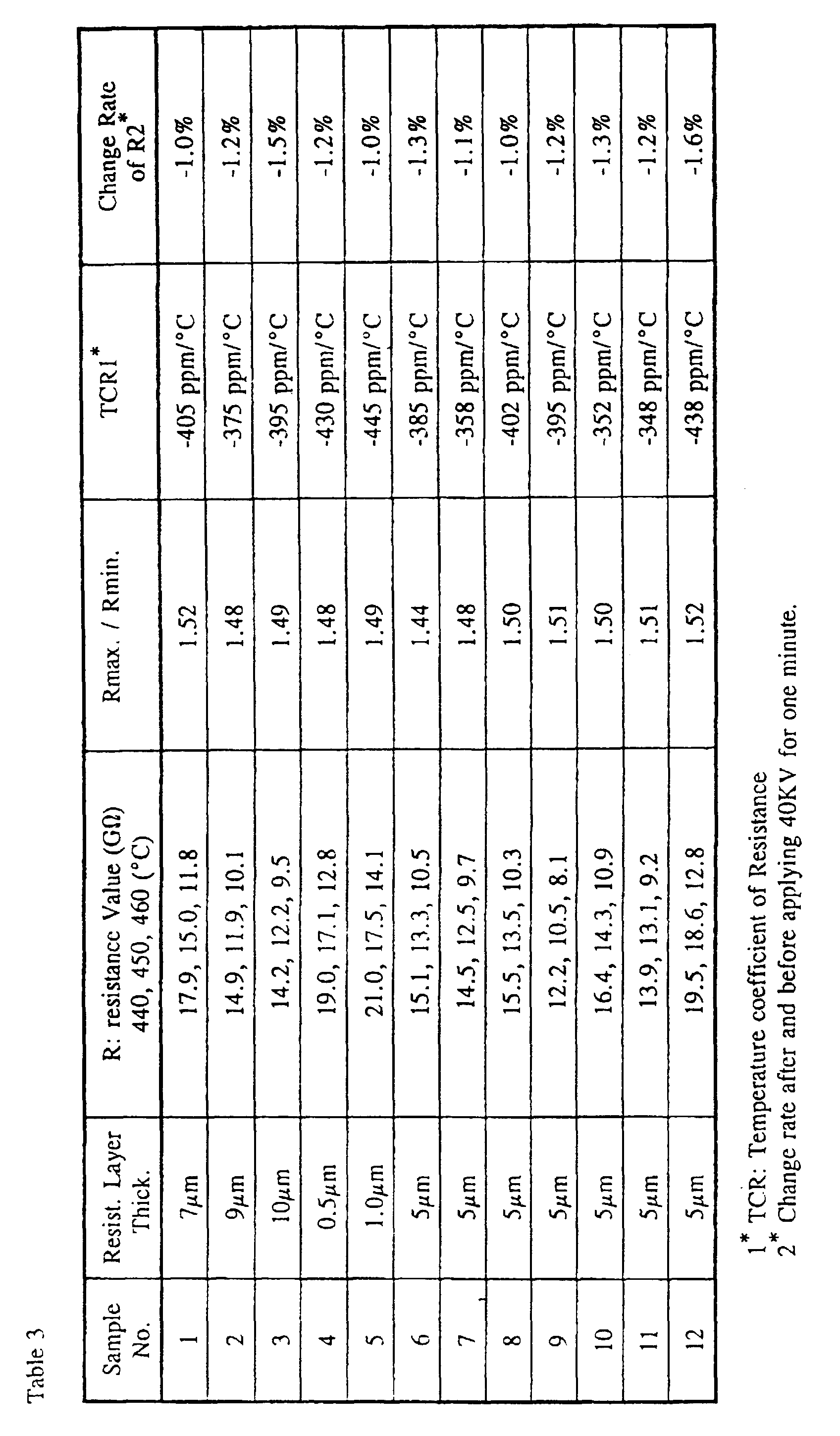
- 40 KV voltage was applied for one minute to an anode (an end of the focusing electrode 15) of each of the resultant cathode ray tubes. It has been found that the magnitude of change in resistance was -1.0%. Results of experiments are shown in Table 1 (setting forth conditions for preparation) and Table 3 (characteristics) wherein Sample No. 1 shows Example 1.
- This glass tube of the specific composition is available from Nippon Denki Garasu Kabushiki Kaisha, Produce # L-29F.
- the viscosity-adjusted resistance paste was applied to the inner surface of the glass tube by immersing the glass tube in a bath containing the viscosity-adjusted resistance paste and then pulling it out of the bath.
- the glass tube having the inner surface coated with the resistance paste was then dried at 80°C to complete a resistance layer of about 12 ⁇ m in thickness on the inner surface of the glass tube.
- the inner surface of the glass tube where the resistance layer was formed is subsequently ground spirally to form a coiled or helical resistance pattern having a plurality of resistance convolutions of a pitch of 300 ⁇ m, 3.5 m in total length exclusive of an intermediate tap, each of said resistance convolutions having a width of 225 ⁇ m with the neighboring resistance convolutions spaced a distance of 75 ⁇ m.
- Each of the internally coated glass tubes was assembled into the corresponding focusing electrode 15 in the cathode ray tube shown in Fig. 1.
- 40 KV voltage was applied for one minute to an anode (an end of the focusing electrode 15) of each of the resultant cathode ray tubes. It has been found that the magnitude of change in resistance was -1.2%. Results of experiments are shown in Table 1 (setting forth conditions for preparation) and Table 3 (characteristics) wherein Sample No. 2 shows Example 2.
- This glass tube of the specific composition is available from Nippon Denki Garasu Kabushiki Kaisha, Produce # BCL.
- the viscosity-adjusted resistance paste was applied to the inner surface of the glass tube by immersing the glass tube in a bath containing the viscosity-adjusted resistance paste and then pulling it out of the bath.
- the glass tube having the inner surface coated with the resistance paste was then dried at 80°C to complete a resistance layer of about 15 ⁇ m in thickness on the inner surface of the glass tube.
- the inner surface of the glass tube where the resistance layer was formed is subsequently ground spirally to form a coiled or helical resistance pattern having a plurality of resistance convolutions of a pitch of 300 ⁇ m, 3.5 m in total length exclusive of an intermediate tap, each of said resistance convolutions having a width of 225 ⁇ m with the neighboring resistance convolutions spaced a distance of 75 ⁇ m.
- Each of the internally coated glass tubes was assembled into the corresponding focusing electrode 15 in the cathode ray tube shown in Fig. 1.
- 40 KV voltage was applied for one minute to an anode (an end of the focusing electrode 15) of each of the resultant cathode ray tubes. It has been found that the magnitude of change in resistance was -1.5%. Results of experiments are shown in Table 1 (setting forth conditions for preparation) and Table 3 (characteristics) wherein Sample No. 3 shows Example 3.
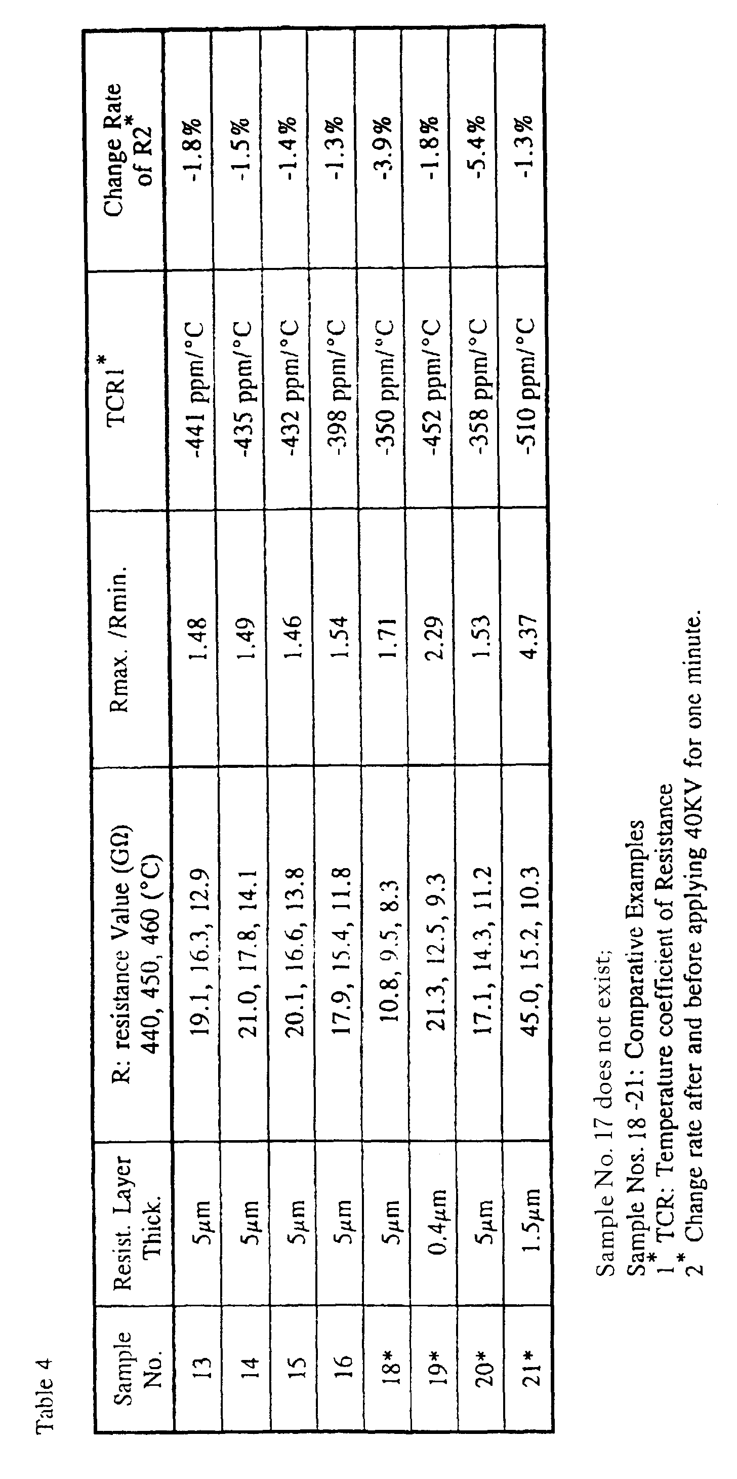
- each of the internally coated glass tubes were prepared except using various kinds of the glass tubes, various composite ratios of RuO 2 and glass powder, various particles of RuO 2 and the glass powder, various thickness of the resistance layer. Results of experiments are shown in Tables 1 to 4 wherein each of Sample No. shows the corresponding Example No. Please note that Samples No. 18 to 21 are comparative Examples, wherein Sample No. 21 is explained subsequent to Examples 27 to 43.
- composition of the glass powder should be set within the preferred scope, otherwise the sintering temperature dependency of the resistance value and TCR will be larger.
- This glass tube of the specific composition is available from Nippon Denki Garasu Kabushiki Kaisha, Produce # L-29F.
- the viscosity-adjusted resistance paste was applied to the inner surface of the glass tube by immersing the glass tube in a bath containing the viscosity-adjusted resistance paste and then pulling it out of the bath.
- the glass tube having the inner surface coated with the resistance paste was then dried at 80°C to complete a resistance layer of about 10 ⁇ m in thickness on the inner surface of the glass tube.
- the inner surface of the glass tube where the resistance layer was formed is subsequently ground spirally to form a coiled or helical resistance pattern having a plurality of resistance convolutions of a pitch of 300 ⁇ m, 3.5 m in total length exclusive of an intermediate tap, each of said resistance convolutions having a width of 225 ⁇ m with the neighboring resistance convolutions spaced a distance of 75 ⁇ m.
- Each of the internally coated glass tubes was assembled into the corresponding focusing electrode 15 in the cathode ray tube shown in Fig. 1.
- 30 KV voltage was applied for 5,000 hours in a constant temperature oven of 70 °C to an anode (an end of the focusing electrode 15) of each of the resultant cathode ray tubes having a vacuum degree of 133.10 -7 Pa (10 -7 Torr). It has been found that the magnitude of change in resistance was 1.3% and no change of spot diameter of the cathode ray tube.
- Results of experiments are shown in Table 5 (setting forth conditions for preparation) and Table 7 (characteristics) wherein Sample No. 22 shows Example 22.
- This glass tube of the specific composition is available from Nippon Denki Garasu Kabushiki Kaisha, Produce # L-29F.
- the viscosity-adjusted resistance paste was applied to the inner surface of the glass tube by immersing the glass tube in a bath containing the viscosity-adjusted resistance paste and then pulling it out of the bath.
- the glass tube having the inner surface coated with the resistance paste was then dried at 80°C to complete a resistance layer of about 10 ⁇ m in thickness on the inner surface of the glass tube.
- the inner surface of the glass tube where the resistance layer was formed is subsequently ground spirally to form a coiled or helical resistance pattern having a plurality of resistance convolutions of a pitch of 300 ⁇ m, 3.5 m in total length exclusive of an intermediate tap, each of said resistance convolutions having a width of 225 ⁇ m with the neighboring resistance convolutions spaced a distance of 75 ⁇ m.
- Each of the internally coated glass tubes was assembled into the corresponding focusing electrode 15 in the cathode ray tube shown in Fig. 1.
- 30 KV voltage was applied for 5,000 hours in a constant temperature oven of 70 °C to an anode (an end of the focusing electrode 15) of each of the resultant cathode ray tubes having a vacuum degree of 133.10 -7 Pa (10 -7 Torr). It has been found that the magnitude of change in resistance was 0.8 % and no change of spot diameter of the cathode ray tube.
- Results of experiments are shown in Table 5 (setting forth conditions for preparation) and Table 8 (characteristics) wherein Sample No. 23 shows Example 23.
- This glass tube of the specific composition is available from Nippon Denki Garasu Kabushiki Kaisha, Produce # BCL.
- the viscosity-adjusted resistance paste was applied to the inner surface of the glass tube by immersing the glass tube in a bath containing the viscosity-adjusted resistance paste and then pulling it out of the bath.
- the glass tube having the inner surface coated with the resistance paste was then dried at 80°C to complete a resistance layer of about 10 ⁇ m in thickness on the inner surface of the glass tube.
- the inner surface of the glass tube where the resistance layer was formed is subsequently ground spirally to form a coiled or helical resistance pattern having a plurality of resistance convolutions of a pitch of 300 ⁇ m, 3.5 m in total length exclusive of an intermediate tap, each of said resistance convolutions having a width of 225 ⁇ m with the neighboring resistance convolutions spaced a distance of 75 ⁇ m.
- Each of the internally coated glass tubes was assembled into the corresponding focusing electrode 15 in the cathode ray tube shown in Fig. 1.
- 30 KV voltage was applied for 5,000 hours in a constant temperature oven of 70 °C to an anode (an end of the focusing electrode 15) of each of the resultant cathode ray tubes having a vacuum degree of 133.10 -7 Pa (10 -7 Torr). It has been found that the magnitude of change in resistance was 1.5 % and no change of spot diameter of the cathode ray tube.
- Results of experiments are shown in Table 5 (setting forth conditions for preparation) and Table 7 (characteristics) wherein Sample No. 24 shows Example 24.
- This glass tube of the specific composition is available from Nippon Denki Garasu Kabushiki Kaisha, Produce # SK-C.
- the viscosity-adjusted resistance paste was applied to the inner surface of the glass tube by immersing the glass tube in a bath containing the viscosity-adjusted resistance paste and then pulling it out of the bath.
- the glass tube having the inner surface coated with the resistance paste was then dried at 80°C to complete a resistance layer of about 10 ⁇ m in thickness on the inner surface of the glass tube.
- the inner surface of the glass tube where the resistance layer was formed is subsequently ground spirally to form a coiled or helical resistance pattern having a plurality of resistance convolutions of a pitch of 300 ⁇ m, 3.5 m in total length exclusive of an intermediate tap, each of said resistance convolutions having a width of 225 ⁇ m with the neighboring resistance convolutions spaced a distance of 75 ⁇ m.
- Each of the internally coated glass tubes was assembled into the corresponding focusing electrode 15 in the cathode ray tube shown in Fig. 1.
- 30 KV voltage was applied for 5,000 hours in a constant temperature oven of 70 °C to an anode (an end of the focusing electrode 15) of each of the resultant cathode ray tubes having a vacuum degree of 133.10 -7 Pa (10 -7 Torr). It has been found that the magnitude of change in resistance was 0.7 % and no change of spot diameter of the cathode ray tube.
- Results of experiments are shown in Table 5 (setting forth conditions for preparation) and Table 7 (characteristics) wherein Sample No. 25 shows Example 25.
- This glass tube of the specific composition is available from Nippon Denki Garasu Kabushiki Kaisha, Produce # L-29F.
- the viscosity-adjusted resistance paste was applied to the inner surface of the glass tube by immersing the glass tube in a bath containing the viscosity-adjusted resistance paste and then pulling it out of the bath.
- the glass tube having the inner surface coated with the resistance paste was then dried at 80°C to complete a resistance layer of about 10 ⁇ m in thickness on the inner surface of the glass tube.
- the inner surface of the glass tube where the resistance layer was formed is subsequently ground spirally to form a coiled or helical resistance pattern having a plurality of resistance convolutions of a pitch of 300 ⁇ m, 3.5 m in total length exclusive of an intermediate tap, each of said resistance convolutions having a width of 225 ⁇ m with the neighboring resistance convolutions spaced a distance of 75 ⁇ m.
- Each of the internally coated glass tubes was assembled into the corresponding focusing electrode 15 in the cathode ray tube shown in Fig. 1.
- 30 KV voltage was applied for 5,000 hours in a constant temperature oven of 70 °C to an anode (an end of the focusing electrode 15) of each of the resultant cathode ray tubes having a vacuum degree of 133.10 -7 Pa (10 -7 Torr). It has been found that the magnitude of change in resistance was 1.3 % and no change of spot diameter of the cathode ray tube.
- Results of experiments are shown in Table 5 (setting forth conditions for preparation) and Table 7 (characteristics) wherein Sample No. 26 shows Example 26.
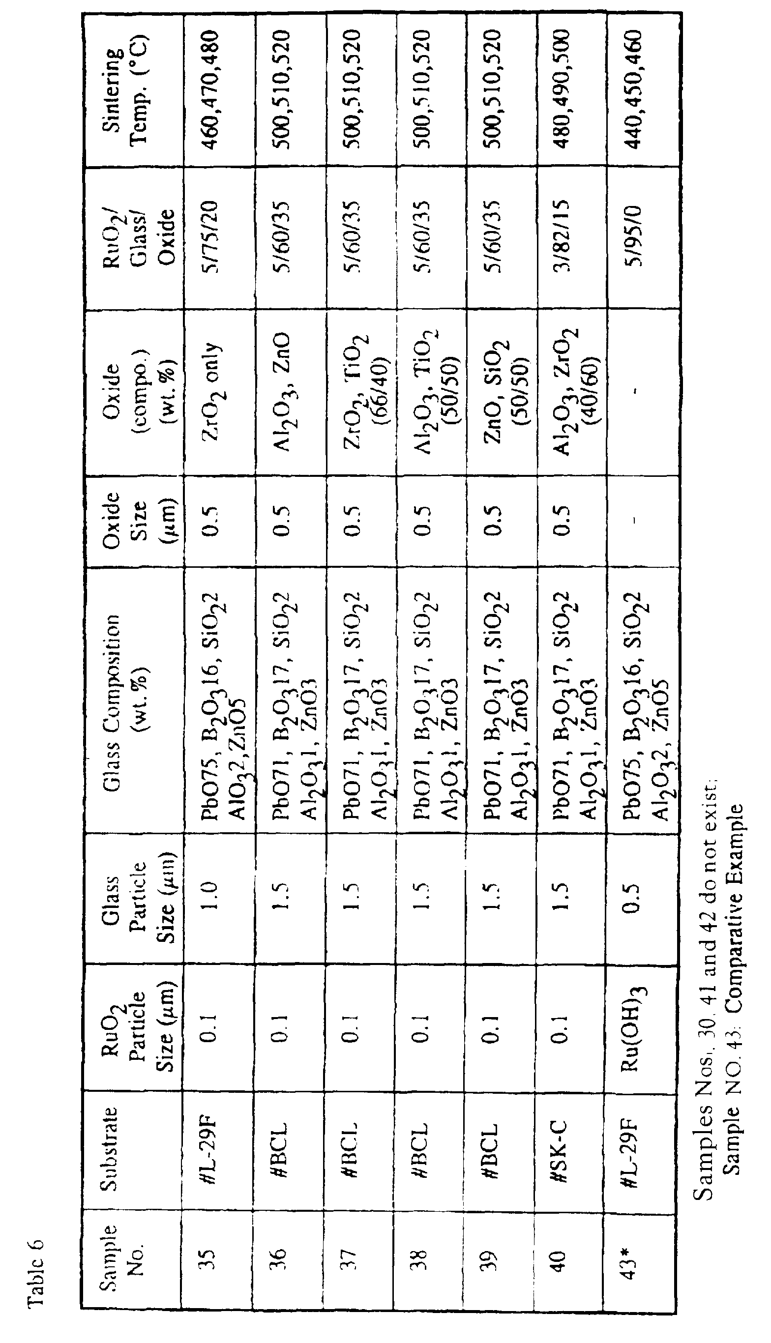
- each of the internally coated glass tubes were prepared except using various kinds of the glass tubes, various composite ratios of RuO 2 , glass powder and metal oxide, various particles of RuO 2 , the glass powder and the metal oxide, various thickness of the resistance layer. Results of experiments are shown in Tables 5 to 8 wherein each of Sample No. shows a corresponding Example No. Please note that Samples No. 41 to 43 are comparative Examples.
- the PbO content in the glass composition is preferably in a range of 69 to 92 wt %, because less than 69 wt% makes the sintering temperature to become over 520 °C, so that it is impossible to form the resistance layer on the glass tube of # LF-29 and #BCL.
- more than 92 wt% does not provide a stable glass composition. If the other element content of the glass powder is out of the scope, the change of the resistance value after applying 30 KV for 5,000 hours becomes large (not preferable).
- the metal oxide may be provided with an insulating and heat resistant property, which prevent the metal oxide from melting into the glass and may be preferably one or mixture of more than two selected from the group consisting of TiO 2 , ZrO 2 , SiO 2 and Al 2 O 3 .
- This glass tube of the specific composition is available from Nippon Denki Garasu Kabushiki Kaisha, Produce # L-29F.
- the suspension so obtained was applied to the inner surface of the glass tube by immersing the glass tube in a bath containing the suspension and then pulling it out of the bath.
- the glass tube having the inner surface coated with the resistance liquid was then dried at 80°C to complete a resistance layer of about 7 ⁇ m in thickness on the inner surface of the glass tube.
- the inner surface of the glass tube where the resistance layer was formed is subsequently ground spirally to form a coiled or helical resistance pattern having a plurality of resistance convolutions of a pitch of 300 ⁇ m, 3.5 m in total length exclusive of an intermediate tap, each of said resistance convolutions having a width of 225 ⁇ m with the neighboring resistance convolutions spaced a distance of 75 ⁇ m.
- Each of the internally coated glass tubes was assembled into the corresponding focuding electrode 15 in the cathode ray tube shown in Fig. 1.
- 40 KV voltage was applied for one minute to an anode (an end of the focusing electrode 15) of each of the resultant cathode ray tubes. It has been found that the magnitude of change in resistance was -1.3%. Results of experiments are shown in Table 1 (setting forth conditions for preparation) and Table 3 (characteristics) wherein Sample No. 21 shows this Comparative Example.
- Fig. 3 is a comparative graph showing the sintenng temperature dependency of the present invnetion and the conventional method.
- a much reliable helical resistance layer on the cathode ray tube having a less sintering temperature dependency of the resistance value and a less resistance load characteristic change on applying a high voltage (30KV in a constant temperature oven of 70 °C) as well as a lens temperature characteristic change.
Landscapes
- Chemical & Material Sciences (AREA)
- Engineering & Computer Science (AREA)
- Materials Engineering (AREA)
- Chemical Kinetics & Catalysis (AREA)
- General Chemical & Material Sciences (AREA)
- Geochemistry & Mineralogy (AREA)
- Life Sciences & Earth Sciences (AREA)
- Organic Chemistry (AREA)
- Manufacturing & Machinery (AREA)
- Microelectronics & Electronic Packaging (AREA)
- Dispersion Chemistry (AREA)
- Composite Materials (AREA)
- Non-Adjustable Resistors (AREA)
- Glass Compositions (AREA)
Description
- The present invention relates to a method of preparing a resistor for cathode ray tube, for example a projection television display tube.
- Referring now to Fig. 2, there is schematically shown a conventional cathode ray tube comprising a sealed glass envelope evacuated to a substantial vacuum. The glass envelope includes a generally
cylindrical neck 22 having one end closed and the other end flared outwardly to define a cone which is in turn continued to afaceplate 21. The illustrated cathode ray tube also comprises acathode 23, an electron gun made up of one or more electronic lens elements, all of which are accommodated within theneck 22. The electron gun shown therein is in the form of a triode electron gun including atriode portion 24 and a mainelectronic lens portion 25 made of metal cylinder, wherein electron beams discharged from thecathode 23 can be led through the mainelectron lens portion 25 to form a crossover image on thefaceplate 21. In such electron lens system, a spot formed on the faceplate has a diameter Ds calculated according to the following formula (1): - Recently, a lot of trials have been made to get a high precision image by making the coefficient of spherical aberration Cs of the main electron lens small and thus achieving a small diameter Ds. Among them, there has been proposed a method wherein instead of the conventional main electron lens comprising plural metal cylinders as the focussing electrode, a new focussing electrode made of a helical resistance element is mounted within the neck of the cathode ray tube as shown in Japanese Patent Publications (unexamined) Nos. Sho 60-208027 and Hei 2-276138.
- According to the conventional method as shown in Japanese Patent Publication No. Sho 61-224402, the helical resistance body can be prepared by dipping a glass tube made of Pb glass material having a softening point of 640 °C into a stable binder-free slurry containing ruthenium hydroxide and glass particles to form an inner coating layer on the glass tube, and then mechanically processing the coating layer in a helical shape after drying, and finally sintering the helical layer to obtain a ruthenium oxide-containing resistance layer.
- However, as the conventional method uses a binder-free suspension containing Ru(OH)2 and glass particles having a low melting temperature during the sintering step which is carried out at 400 to 600 °C, Ru(OH)2 is thermally decomposed and produces RuO2. At same time, the glass particles are softened, so that the resulting resistance layer comprises very fine RuO2 particles which have a size of 0.01 to 0.03 µm and are crystallized around the glass particles. If a high resistance value of 10 GΩ (corresponding to a sheet resistivity of 1 MΩ/□) would be required, the problem occurs that the sintering temperature dependency of the resistance value is increased, that is, a small change in the sintering temperature causes a large change of the resistance value and thus the temperature coefficient of resistance (TCR) increases.
- On the other hand, there is provided another method for preparing the resistance layer from RuO2 and glass particles as shown in Japanese Patent No. Sho 55-14627. However, the resulting RuO2-Glass resistance layer is used for a potential divider and is prepared on a substrate of Al2O3 by a screen printing. There are some problems that the total resistance value reaches only to 300 to 1000 MΩ and a relatively high sintering temperature of 750 to 850 °C is needed to prepare a high reliable resistor against a high voltage of about 30 KV and an electron ray because of using an alumina substrate (Heat expansion coefficient: 75X10-7 /°C; Melting point: 2050 °C) and the glass component in the resulting glaze resistor having a high melting point. Therefore, such a method can not apply to preparation of the resistance layer on the glass tube in the cathode ray tube because the glass tube is made of a low melting point glass material.
- EP-A1 0 513 909 discloses an electron-optical device comprising a cathode-ray tube having a cylindrical neck of a very small external diameter, particularly ≤ 15 mm, whose inner surface carries a multi-element layer electrode such as a helical structure formed from a high-ohmic resistance material, which structure constitutes a focusing lens. In combination with a deflection system having a correspondingly small diameter, very high scanning frequencies can be realised.
- US-Patent 4 961 022 describes a display tube comprising an electron gun having a beam-shaping part and a focusing structure. The focusing structure comprises an elongate hollow structure with a high-ohmic resistive layer provided on the inner and/or outer surface and comprises means for forming a non-rotationally symmetrical lens element in the area of the focusing structure. This may be a structure generating an electric multipole (for example, dipole or quadrupole) which may be incorporated particularly in the high-ohmic resistive layer.
- US-Patent 4 961 023 relates to a cathode ray tube having an electron gun which comprises a beam-shaping part and a focusing structure, which structure comprises a hollow tube with a helical electrically conducting glass-enamel layer on the inner surface. Together with the hollow tube, the components of the beam-shaping part are secured to axial mounting rods via metal supporting elements. The tube has a first and a second end face each of which is fixedly connected in one embodiment to a metal plate having a coaxial opening provided with a flange, which flange projects into the tube and is fused in an electrically conducting manner to the electrically conducting glass-enamel layer of the focusing structure.
- US-Patent 5 021 194 discloses a thermal head obtained by calcining a mixed material comprising at least ruthenium oxide particles having a specific surface area of 10 to 40 m2/g and a particle size of 1 µm as the upper limit value of the particle size distribution. Glass fine particles and a dispersant which disperses these fine values and disappears by calcining can reduce scattering of resistance values and give high image quality at thermal printing.
- US-Patent 4 574 055 relates to a resistor composition comprising conductive particles, a glass frit and a vehicle in which RuO2 particles coated with a polynary oxide of Bi and/or Pb and Ru are employed and, by using the surface-coated RuO2, the composition can provide readily an improved resistor having an advantageous combination of properties, particularly a small absolute TCR and high voltage stability throughout a wide resistance range. The produced resistor can be successfully laser-trimmed without adversely affecting the properties thereof.
- US-Patent 4 101 708 describes resistor compositions of inorganic powders dispersed in an inert vehicle for making film resistors on dielectric substrates. The powders comprise certain proportions of RuO2, PbO-containing glass, Nb2O5 and, optionally, CaF2. Also sintered resistors thereof adherent to such substrates.
- It is the object of the present invention to overcome the above explained prior art disadvantages and to provide a sintering method for preparing a high resistance layer on a glass tube having a low melting temperature and being intended for use in a cathode ray tube, which method leads to a high resistance layer that shows a low resistance dependency on the sintering temperature, while being stable against high voltage and showing a stable load characteristic.
- This object is attained by the methods according to claims 1 and 7. Suitable and preferred embodiments of the methods are defined in the respective subclaims.
- After deep going research made by the inventors, it was found that an optimization of the composition and of the particle sizes of the resistance layer components leads to a more reliable resistance layer at a high region of 10 GΩ (corresponding to a sheet resistivity of 1 MΩ/□), provided with less dependency on the sintering temperature, more stability against the high voltage, a stable load characteristic and a less temperature characteristic of the resistance value. That is, provided that the resistance layer contains a small ratio such as 1 to 15% by weight of the RuO2 component, the RuO2 particles have a relatively large size of 0.05 to 0.4 µm, and the glass particles have a small size of 0.01 to 2.0 µm, the desired high sheet resistivity of 1 MΩ/□ and low TCR can be always obtained even if the sintering step of the resistance layer would be carried out at a low temperature of around 500 °C. Further, a good short-time overload of ± 2 % or less and a low TCR of ± 450 ppm/°C or less can be obtained, provided that the glass composition and the sintering condition are optimized.
- Accordingly, from a first aspect of the present invention there is provided a method of preparing a resistor for cathode ray tube which comprises steps of claim 1.
- The resulting RuO2-glass glaze resistor has a structure after sintering wherein RuO2 particles are dispersed in a network of glass particles, for example as shown in Journal of American Ceramic Society, 73 vol. No.7 (1990) page 1953.
- The glass composition may be adjusted to fit a coefficient of thermal expansion to that of the glass tube, the preferred examples are shown as follows.
- 1) 67 to 95 wt. % of PbO, 2 to 15 wt. % of SiO2 and 3 to 19 wt. % of B2O3.
- 2) 69 to 90 wt.% of PbO, 2 to 20 wt.% of ZnO and 5 to 15 wt.% of B2O3.
- 3) 40 to 52 wt.% of P2O5, 34 to 56 wt.% of ZnO and 4 to 14 wt.% of Al2O3.
- 4) 15 to 30 wt.% of ZnO, 5 to 25 wt. % of B2O3 and 50 to 75 wt.% of V2O5.
- 5) 69 to 92 wt. % of PbO, 2 to 10 wt. % of SiO2, 2 to 20 wt. % of B2O3, 1 to 5 wt.% of Al2O3, and 2 to 5 wt.% of ZnO.
-
- On the other hand, considering a low temperature sintering step according to the present invention, the glass tube has preferably a glass transition point Tg of 600 °C or less. The typical compositions of the glass tube is shown as follows.
- 1) PbO2 28 wt. %, SiO2 60 wt. %, Al2O3 1 wt. %, Na2O 8 wt. %, K2O 3 wt. %
- 2) SiO2 72 wt.%, Al2O3 7 wt.%, B2O3 10.5 wt.%, BaO 3 wt.%, Na2O 7.5 wt. %.
-
- In addition to the above composition, metal oxide particles may be added. Therefore, according to a second aspect of the present invention there is provided a method of preparing a resistor for cathode ray tube which comprises steps of claim 7.
- In a preferred embodiment according to the second invention, the glass powder may comprises:
- 1) 69 to 92 wt.% of PbO, 2 to 10 wt. % of SiO2, 2 to 20 wt. % of BO, 1 to 5 wt. % of Al2O3, and 2 to 5 wt.% of ZnO.
- 2) 67 to 95 wt. % of PbO, 2 to 15 wt. % of SiO2 and 3 to 19 wt. % of B2O3.
-
- In a preferred embodiment, the metal oxide powder may be at least one selected from the group consisting of TiO2, ZrO2, ZnO, SiO2 and Al2O3.
- This and other objects and features of the present invention will become clear from the following description taken in conjunction with preferred embodiments thereof with reference to the accompanying drawings, in which like parts are designated by like reference numerals and in which:
- Fig. 1 is a vertical sectional view of a cathode ray tube according to an embodiment of the present invention;
- Fig. 2 is a vertical sectional view of a conventional cathode ray tube;
- Fig. 3 is a graph showing comparative data concerning the resistance value dependency on the sintering temperature in resistance layers prepared by the present invention and the conventional method.
-
- Referring now to Fig. 1, there is schematically shown a cathode ray tube comprising a sealed glass envelope evacuated to a substantial vacuum. The glass envelope includes a generally
cylindrical neck 12 having one end closed and the other end flared outwardly to define a cone which is in turn continued to a faceplate 11. The illustrated cathode ray tube also comprises acathode 13, an electron gun made up of one or more electronic lens elements, all of which are accommodated within theneck 12. The electron gun shown therein is in the form of a triode electron gun including atriode 14 and a focusingelectrode 15. The focusingelectrode 15 is formed by the use of a spiral resistance element. - A glass tube for the focusing
electrode 15 to be accommodated within theneck 12 of the glass envelope, 10 mm in diameter and 65 mm in length, was prepared, from a composition consisting of 60 wt% of SiO2, 28 wt% of PbO, 8 wt% of Na2O, 3 wt% of K2O and 1 wt% of Al2O3 and also having a coefficient of thermal expansion of 94 × 10-7/°C. This glass tube of the specific composition is available from Nippon Denki Garasu Kabushiki Kaisha, Produce # L-29F. - 3 parts by weight of powdery particles of ruthenium oxide (RuO2) of 0.05 µm in average particle size and 97 parts by weight of a glass powder consisting of:85 wt% of PbO, 10 wt% of B2O3 and 5 wt% of SiO2 and having an average particle size of 0.1 µm were mixed together and kneaded by the use of a known triple-roll kneader together with terpineol dissolved with 10% ethylcellulose as an organic binder, to thereby provide a resistance paste. The resistance paste so obtained is, prior to application to an inner surface of the glass tube, added with a toluene solvent to adjust its viscosity to 50 dPa.s (poises) per centimeter.
- The viscosity-adjusted resistance paste was applied to the inner surface of the glass tube by immersing the glass tube in a bath containing the viscosity-adjusted resistance paste and then pulling it out of the bath. The glass tube having the inner surface coated with the resistance paste was then dried at 80°C to complete a resistance layer of about 10 µm in thickness on the inner surface of the glass tube.
- Using a diamond bite, the inner surface of the glass tube where the resistance layer was formed is subsequently ground spirally to form a coiled or helical resistance pattern having a plurality of resistance convolutions of a pitch of 300 µm, 3.5 m in total length exclusive of an intermediate tap, each of said resistance convolutions having a width of 225 µm with the neighboring resistance convolutions spaced a distance of 75 µm.
- Two additional internally coated glass tubes identical to the internally coated glass tube discussed above were also prepared. All these three internally coated glass tubes were baked in tunnel furnaces capable of baking them for ten minutes at 440°C, 450°C and 460°C, respectively. The resistance layers on the inner surfaces of the respective glass tubes were about 7 µm in thickness, exhibiting a total resistance of 17.9 GΩ, 15.0 GΩ and 11.8 GΩ. (Sheet resistance values of each of those resistance layers on the respective glass tubes were 3.6 MΩ/□, 3.0 MΩ/□ and 2.4 MΩ/□, and the ratio of Rmax / Rmin, was 1.52 within the sintering temperature from 440 to 460 °C. Both temperature dependent change of the resistance value at a temperature within the range of 0 to 125 °C and temperature coefficient of resistance (TCR), exhibited by all of the layers on the inner surfaces of those glass tubes, were -405 ppm/°C.
- Each of the internally coated glass tubes was assembled into the corresponding focusing
electrode 15 in the cathode ray tube shown in Fig. 1. To determine the magnitude of change in resistance, 40 KV voltage was applied for one minute to an anode (an end of the focusing electrode 15) of each of the resultant cathode ray tubes. It has been found that the magnitude of change in resistance was -1.0%. Results of experiments are shown in Table 1 (setting forth conditions for preparation) and Table 3 (characteristics) wherein Sample No. 1 shows Example 1.

- A glass tube for the focusing
electrode 15 to be accommodated within theneck 12 of the glass envelope, 10 mm in diameter and 65 mm in length, was prepared in a similar way to Example 1, from a composition consisting of 60 wt% of SiO2, 28 wt% of PbO, 8 wt% of Na2O, 3 wt% of K2O and 1 wt% of Al2O3 and also having a coefficient of thermal expansion of 94 × 10-7/°C. This glass tube of the specific composition is available from Nippon Denki Garasu Kabushiki Kaisha, Produce # L-29F. - 5 parts by weight of powdery particles of ruthenium oxide (RuO2) of 0.1 µm in average particle size and 95 parts by weight of a glass powder consisting of:80 wt% of PbO, 15 wt% of B2O3 and 5 wt% of SiO2 and having an average particle size of 0.5 µm were mixed together and were kneaded by the use of a known triple-roll kneader together with terpineol dissolved with 10% ethylcellulose as an organic binder, to thereby provide a resistance paste. The resistance paste so obtained is, prior to application to an inner surface of the glass tube, added with a toluene solvent to adjust its viscosity to 50 dPa.s (poises) per centimeter.
- The viscosity-adjusted resistance paste was applied to the inner surface of the glass tube by immersing the glass tube in a bath containing the viscosity-adjusted resistance paste and then pulling it out of the bath. The glass tube having the inner surface coated with the resistance paste was then dried at 80°C to complete a resistance layer of about 12 µm in thickness on the inner surface of the glass tube.
- Using a diamond bite, the inner surface of the glass tube where the resistance layer was formed is subsequently ground spirally to form a coiled or helical resistance pattern having a plurality of resistance convolutions of a pitch of 300 µm, 3.5 m in total length exclusive of an intermediate tap, each of said resistance convolutions having a width of 225 µm with the neighboring resistance convolutions spaced a distance of 75 µm.
- Two additional internally coated glass tubes identical to the internally coated glass tube discussed above were also prepared. All these three internally coated glass tubes were baked tunnel furnaces capable of baking them for ten minutes at 440°C, 450°C and 460°C, respectively. At this time, the resistance layers on the inner surfaces of the respective glass tubes were about 9 µm in thickness, exhibiting the total resistance of 14.9 GΩ, 11.9 GΩ and 10.1 GΩ. (Sheet resistance values of each of those resistance layers on the respective glass tubes were 3.0 MΩ/□, 2.4 MΩ/□ and 2.0 MΩ/□, and a ration of Rmax / Rmin. was 1.48 within the sintering temperature change from 440 to 460 °C. Both temperature dependent change of the resistance value at a temperature within the range of 0 to 125°C and temperature coefficient of resistance (TCR), exhibited by all of the layers on the inner surfaces of those glass tubes, were -375 ppm/°C.
- Each of the internally coated glass tubes was assembled into the corresponding focusing
electrode 15 in the cathode ray tube shown in Fig. 1. To determine the magnitude of change in resistance, 40 KV voltage was applied for one minute to an anode (an end of the focusing electrode 15) of each of the resultant cathode ray tubes. It has been found that the magnitude of change in resistance was -1.2%. Results of experiments are shown in Table 1 (setting forth conditions for preparation) and Table 3 (characteristics) wherein Sample No. 2 shows Example 2. - A glass tube for the focusing
electrode 15 to be accommodated within theneck 12 of the glass envelope, 10 mm in diameter and 65 mm in length, was prepared in a similar way to Example 1, from a composition consisting of 72 wt% of SiO2, 3 wt% of BaO, 10.5 wt% of B2O3, 7.5 wt% of Na2O and 7 wt% of Al2O3 and also having a coefficient of thermal expansion of 52 × 10-7/°C. This glass tube of the specific composition is available from Nippon Denki Garasu Kabushiki Kaisha, Produce # BCL. - 15 parts by weight of powdery particles of ruthenium oxide (RuO2) of 0.4 µm in average particle size and 85 parts by weight of a glass powder consisting of 56 wt% of ZnO, 4 wt% of Al2O3 and 40 wt% of P2O5 and having an average particle size of 1.5 µm were mixed together and were kneaded by the use of a known triple-roll kneader together with terpineol dissolved with 10% ethylcellulose as an organic binder, to thereby provide a resistance paste. The resistance paste so obtained is, prior to application to an inner surface of the glass tube, added with a toluene solvent to adjust its viscosity to 50 dPa.s (poises) per centimeter.
- The viscosity-adjusted resistance paste was applied to the inner surface of the glass tube by immersing the glass tube in a bath containing the viscosity-adjusted resistance paste and then pulling it out of the bath. The glass tube having the inner surface coated with the resistance paste was then dried at 80°C to complete a resistance layer of about 15 µm in thickness on the inner surface of the glass tube.
- Using a diamond bite, the inner surface of the glass tube where the resistance layer was formed is subsequently ground spirally to form a coiled or helical resistance pattern having a plurality of resistance convolutions of a pitch of 300 µm, 3.5 m in total length exclusive of an intermediate tap, each of said resistance convolutions having a width of 225 µm with the neighboring resistance convolutions spaced a distance of 75 µm.
- Two additional internally coated glass tubes identical to the internally coated glass tube discussed above were also prepared. All these three internally coated glass tubes were baked tunnel furnaces capable of baking them for ten minutes at 490°C, 500°C and 510°C, respectively. At this time, the resistance layers on the inner surfaces of the respective glass tubes were about 10 µm in thickness, exhibiting the total resistance of 14.2 GΩ, 12.2 GΩ and 9.5 GΩ. (Sheet resistance values of each of those resistance layers on the respective glass tubes were 2.8 MΩ/□, 2.4 MΩ/□ and 1.9 MΩ/□, and a ration of Rmax / Rmin. was 1.49 within the sintering temperature change from 490 to 510 °C. Both temperature dependent change of the resistance value at a temperature within the range of 0 to 125°C and temperature coefficient of resistance (TCR), exhibited by all of the layers on the inner surfaces of those glass tubes, were - 395 ppm/°C.
- Each of the internally coated glass tubes was assembled into the corresponding focusing
electrode 15 in the cathode ray tube shown in Fig. 1. To determine the magnitude of change in resistance, 40 KV voltage was applied for one minute to an anode (an end of the focusing electrode 15) of each of the resultant cathode ray tubes. It has been found that the magnitude of change in resistance was -1.5%. Results of experiments are shown in Table 1 (setting forth conditions for preparation) and Table 3 (characteristics) wherein Sample No. 3 shows Example 3. - In a similar way to Examples 1 to 3, each of the internally coated glass tubes were prepared except using various kinds of the glass tubes, various composite ratios of RuO2 and glass powder, various particles of RuO2 and the glass powder, various thickness of the resistance layer. Results of experiments are shown in Tables 1 to 4 wherein each of Sample No. shows the corresponding Example No. Please note that Samples No. 18 to 21 are comparative Examples, wherein Sample No. 21 is explained subsequent to Examples 27 to 43.
- Apparent from the experiment data shown in Tables 1 to 4, it has been found that smaller than 0.05 µm of RuO2 particles makes the sintering temperature dependency of the resistance value to increase while larger than 0.4 µm of that makes the resistance value changeability after applying 40 KV for one minute to increase.
- Further, it has been found that smaller than 0.01 µm of average particle size of glass powder makes their dispersion property to be worse, resulting in gelatinization of the resistance paste which can not be coated while larger than 2.0 µm makes the glass powder and RuO2 to be separated, which causes preparation of ununiform resistance layer.
- Furthermore, it has been found that thinner than 0.5 µm of the resistance layer after sintering makes the resistance value to be scattered largely while thicker than 10 µm of that makes accurate helical processing by a diamond bite to be difficult.
- The composition of the glass powder should be set within the preferred scope, otherwise the sintering temperature dependency of the resistance value and TCR will be larger.
- A glass tube for the focusing
electrode 15 to be accommodated within theneck 12 of the glass envelope, 10 mm in diameter and 65 mm in length, was prepared, from a composition consisting of 60 wt% of SiO2, 28 wt% of PbO, 8 wt% of Na2O, 3 wt% of K2O and 1 wt% of Al2O3 and also having a coefficient of thermal expansion of 94 × 10-7/°C. This glass tube of the specific composition is available from Nippon Denki Garasu Kabushiki Kaisha, Produce # L-29F. - 3 parts by weight of powdery particles of ruthenium oxide (RuO2) of 0.05 µm in average particle size and 97 parts by weight of a glass powder consisting of 82 wt% of PbO, 5 wt% of B2O3, 10 wt% of SiO2, 1 wt% of Al2O3, 2 wt% of ZnO and having an average particle size of 0.1 µm were mixed together and were kneaded by the use of a known triple-roll kneader together with terpineol dissolved with 10% ethylcellulose as an organic binder, to thereby provide a resistance paste. The resistance paste so obtained is, prior to application to an inner surface of the glass tube, added with a toluene solvent to adjust its viscosity to 50 dPa.s (poises) per centimeter.
- The viscosity-adjusted resistance paste was applied to the inner surface of the glass tube by immersing the glass tube in a bath containing the viscosity-adjusted resistance paste and then pulling it out of the bath. The glass tube having the inner surface coated with the resistance paste was then dried at 80°C to complete a resistance layer of about 10 µm in thickness on the inner surface of the glass tube.
- Using a diamond bite, the inner surface of the glass tube where the resistance layer was formed is subsequently ground spirally to form a coiled or helical resistance pattern having a plurality of resistance convolutions of a pitch of 300 µm, 3.5 m in total length exclusive of an intermediate tap, each of said resistance convolutions having a width of 225 µm with the neighboring resistance convolutions spaced a distance of 75 µm.
- Two additional internally coated glass tubes identical to the internally coated glass tube discussed above were also prepared. All these three internally coated glass tubes were baked tunnel furnaces capable of baking them for ten minutes at 440°C, 450°C and 460°C, respectively. At this time, the resistance layers on the inner surfaces of the respective glass tubes were about 7.5 µm in thickness, exhibiting the total resistance of 17.8 GΩ, 15.3 GΩ and 12.8 GΩ. (Sheet resistance values of each of those resistance layers on the respective glass tubes were 3.6 MΩ/□, 3.1 MΩ/□ and 2.6 MΩ/□, and a ratio of Rmax / Rmin. was 1.39 within the sintering temperature from 440 to 460 °C. Both temperature dependent change of the resistance value at a temperature within the range of 0 to 125 °C and temperature coefficient of resistance (TCR), exhibited by all of the layers on the inner surfaces of those glass tubes, were -345 ppm/°C.
- Each of the internally coated glass tubes was assembled into the corresponding focusing
electrode 15 in the cathode ray tube shown in Fig. 1. To determine the magnitude of change in resistance, 30 KV voltage was applied for 5,000 hours in a constant temperature oven of 70 °C to an anode (an end of the focusing electrode 15) of each of the resultant cathode ray tubes having a vacuum degree of 133.10-7 Pa (10-7 Torr). It has been found that the magnitude of change in resistance was 1.3% and no change of spot diameter of the cathode ray tube. Results of experiments are shown in Table 5 (setting forth conditions for preparation) and Table 7 (characteristics) wherein Sample No. 22 shows Example 22.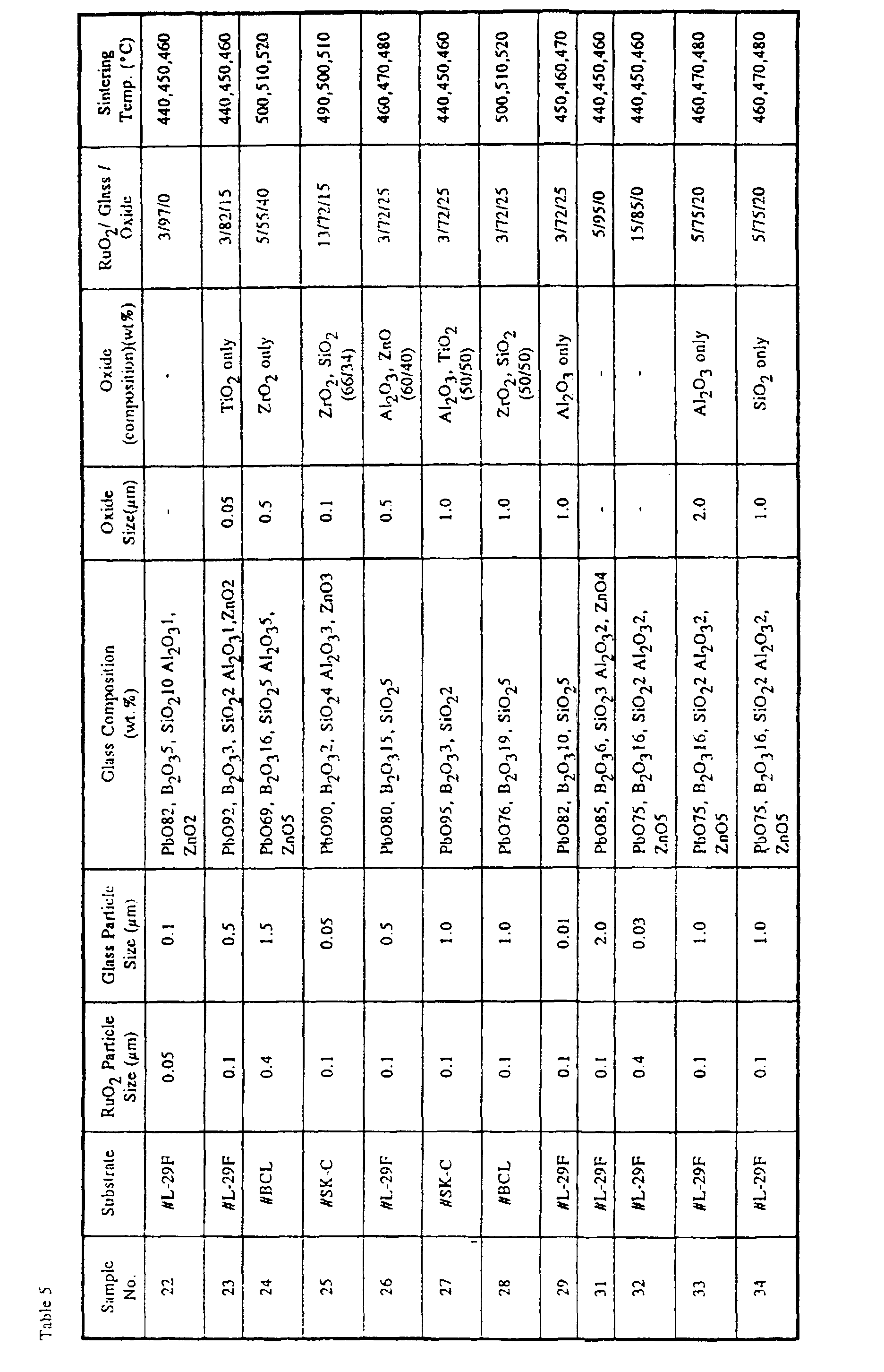


- A glass tube for the focusing
electrode 15 to be accommodated within theneck 12 of the glass envelope, 10 mm in diameter and 65 mm in length, was prepared in a similar way to Example 22, from a composition consisting of 60 wt% of SiO2, 28 wt% of PbO, 8 wt% of Na2O, 3 wt% of K2O and 1 wt% of Al2O3 and also having a coefficient of thermal expansion of 94 × 10-7/°C. This glass tube of the specific composition is available from Nippon Denki Garasu Kabushiki Kaisha, Produce # L-29F. - 3 parts by weight of powdery particles of ruthenium oxide (RuO2) of 0.1 µm in average particle size, 82 parts by weight of a glass powder consisting of 92 wt% of PbO, 3 wt% of B2O3, 2 wt% of SiO2, 1 wt% of Al2O3 and 2 wt.% of ZnO and having an average particle size of 0.5 µm and 15 parts by weight of the metal oxide (TiO2) were mixed together and were kneaded by the use of a known triple-roll kneader together with terpineol dissolved with 10% ethylcellulose as an organic binder, to thereby provide a resistance paste. The resistance paste so obtained is, prior to application to an inner surface of the glass tube, added with a toluene solvent to adjust its viscosity to 50 dPa.s (poises) per centimeter.
- The viscosity-adjusted resistance paste was applied to the inner surface of the glass tube by immersing the glass tube in a bath containing the viscosity-adjusted resistance paste and then pulling it out of the bath. The glass tube having the inner surface coated with the resistance paste was then dried at 80°C to complete a resistance layer of about 10 µm in thickness on the inner surface of the glass tube.
- Using a diamond bite, the inner surface of the glass tube where the resistance layer was formed is subsequently ground spirally to form a coiled or helical resistance pattern having a plurality of resistance convolutions of a pitch of 300 µm, 3.5 m in total length exclusive of an intermediate tap, each of said resistance convolutions having a width of 225 µm with the neighboring resistance convolutions spaced a distance of 75 µm.
- Two additional internally coated glass tubes identical to the internally coated glass tube discussed above were also prepared. All these three internally coated glass tubes were baked tunnel furnaces capable of baking them for ten minutes at 440°C, 450°C and 460°C, respectively. At this time, the resistance layers on the inner surfaces of the respective glass tubes were about 9 µm in thickness, exhibiting the total resistance of 14.1 GΩ, 12.0 GΩ and 11.2 GΩ. (Sheet resistance values of each of those resistance layers on the respective glass tubes were 2.8 MΩ/□, 2.6 MΩ/□ and 2.4 MΩ/□, and a ration of Rmax / Rmin. was 1.26 within the sintering temperature change from 440 to 460 °C. Both temperature dependent change of the resistance value at a temperature within the range of 0 to 125°C and temperature coefficient of resistance (TCR), exhibited by all of the layers on the inner surfaces of those glass tubes, were -315 ppm/°C.
- Each of the internally coated glass tubes was assembled into the corresponding focusing
electrode 15 in the cathode ray tube shown in Fig. 1. To determine the magnitude of change in resistance, 30 KV voltage was applied for 5,000 hours in a constant temperature oven of 70 °C to an anode (an end of the focusing electrode 15) of each of the resultant cathode ray tubes having a vacuum degree of 133.10-7 Pa (10-7 Torr). It has been found that the magnitude of change in resistance was 0.8 % and no change of spot diameter of the cathode ray tube. Results of experiments are shown in Table 5 (setting forth conditions for preparation) and Table 8 (characteristics) wherein Sample No. 23 shows Example 23. - A glass tube for the focusing
electrode 15 to be accommodated within theneck 12 of the glass envelope, 10 mm in diameter and 65 mm in length, was prepared in a similar way to Example 22, from a composition consisting of 72 wt% of SiO2, 3 wt% of BaO, 10.5 wt% of B2O3, 7.5 wt% of Na2O and 7 wt% of Al2O3 and also having a coefficient of thermal expansion of 52 × 10-7/°C. This glass tube of the specific composition is available from Nippon Denki Garasu Kabushiki Kaisha, Produce # BCL. - 5 parts by weight of powdery particles of ruthenium oxide (RuO2) of 0.4 µm in average particle size and 55 parts by weight of a glass powder consisting of 69 wt% of PbO, 16 wt% of B2O3, 5 wt% of SiO2, 5 wt% of Al2O3 and 5 wt% of ZnO and having an average particle size of 1.5 µm and 40 parts by weight of metal oxide (ZrO2) having a particle size of 0.5 µm were mixed together and were kneaded by the use of a known triple-roll kneader together with a terpineol dissolved with 10% ethylcellulose as an organic binder, to thereby provide a resistance paste. The resistance paste so obtained is, prior to application to an inner surface of the glass tube, added with a toluene solvent to adjust its viscosity to 50 dPa.s (poises) per centimeter.
- The viscosity-adjusted resistance paste was applied to the inner surface of the glass tube by immersing the glass tube in a bath containing the viscosity-adjusted resistance paste and then pulling it out of the bath. The glass tube having the inner surface coated with the resistance paste was then dried at 80°C to complete a resistance layer of about 10 µm in thickness on the inner surface of the glass tube.
- Using a diamond bite, the inner surface of the glass tube where the resistance layer was formed is subsequently ground spirally to form a coiled or helical resistance pattern having a plurality of resistance convolutions of a pitch of 300 µm, 3.5 m in total length exclusive of an intermediate tap, each of said resistance convolutions having a width of 225 µm with the neighboring resistance convolutions spaced a distance of 75 µm.
- Two additional internally coated glass tubes identical to the internally coated glass tube discussed above were also prepared. All these three internally coated glass tubes were baked tunnel furnaces capable of baking them for ten minutes at 500°C, 510°C and 520°C; respectively. At this time, the resistance layers on the inner surfaces of the respective glass tubes were about 7.8 µm in thickness, exhibiting the total resistance of 13.6 GΩ, 12.6 GΩ and 10.8 GΩ (Sheet resistance values of each of those resistance layers on the respective glass tubes were 2.7 MΩ/□, 2.5 MΩ/□ and 2.1 MΩ/□, and a ration of Rmax / Rmin. was 1.26 within the sintering temperature change from 500 to 520 °C. Both temperature dependent change of the resistance value at a temperature within the range of 0 to 125°C and temperature coefficient of resistance (TCR), exhibited by all of the layers on the inner surfaces of those glass tubes, were - 305 ppm/°C.
- Each of the internally coated glass tubes was assembled into the corresponding focusing
electrode 15 in the cathode ray tube shown in Fig. 1. To determine the magnitude of change in resistance, 30 KV voltage was applied for 5,000 hours in a constant temperature oven of 70 °C to an anode (an end of the focusing electrode 15) of each of the resultant cathode ray tubes having a vacuum degree of 133.10-7 Pa (10-7 Torr). It has been found that the magnitude of change in resistance was 1.5 % and no change of spot diameter of the cathode ray tube. Results of experiments are shown in Table 5 (setting forth conditions for preparation) and Table 7 (characteristics) wherein Sample No. 24 shows Example 24. - A glass tube for the focusing
electrode 15 to be accommodated within theneck 12 of the glass envelope, 10 mm in diameter and 65 mm in length, was prepared in a similar way to Example 22, from a composition consisting of 70.3 wt% of SiO2, 1.2 wt% of B2O3, 17.8 wt% of Na2O, 2 wt% of Al2O3, 2.8 wt% of MgO and 5.9 wt% of CaO and also having a coefficient of thermal expansion of 98.5 × 10⁻⁷/°C. This glass tube of the specific composition is available from Nippon Denki Garasu Kabushiki Kaisha, Produce # SK-C. - 13 parts by weight of powdery particles of ruthenium oxide (RuO2) of 0.1 µm in average particle size and 72 parts by weight of a glass powder consisting of 90 wt% of PbO, 2 wt% of B2O3, 4 wt% of SiO2, 3 wt% of Al2o3 and 3 wt% of ZnO and having an average particle size of 0.05 µm and 15 parts by weight of mixed metal oxides (ZrO2 and SiO2; 66:34) having each particle size of 0.1 µm were mixed together and were kneaded by the use of a known triple-roll kneader together with a terpineol dissolved with 10% ethylcellulose as an organic binder, to thereby provide a resistance paste. The resistance paste so obtained is, prior to application to an inner surface of the glass tube, added with a toluene solvent to adjust its viscosity to 50 dPa.s (poises) per centimeter.
- The viscosity-adjusted resistance paste was applied to the inner surface of the glass tube by immersing the glass tube in a bath containing the viscosity-adjusted resistance paste and then pulling it out of the bath. The glass tube having the inner surface coated with the resistance paste was then dried at 80°C to complete a resistance layer of about 10 µm in thickness on the inner surface of the glass tube.
- Using a diamond bite, the inner surface of the glass tube where the resistance layer was formed is subsequently ground spirally to form a coiled or helical resistance pattern having a plurality of resistance convolutions of a pitch of 300 µm, 3.5 m in total length exclusive of an intermediate tap, each of said resistance convolutions having a width of 225 µm with the neighboring resistance convolutions spaced a distance of 75 µm.
- Two additional internally coated glass tubes identical to the internally coated glass tube discussed above were also prepared. All these three internally coated glass tubes were baked tunnel furnaces capable of baking them for ten minutes at 490°C, 500°C and 510°C, respectively. At this time, the resistance layers on the inner surfaces of the respective glass tubes were about 8.0 µm in thickness, exhibiting the total resistance of 6.5 GΩ, 5.1 GΩ and 5.0 GΩ (Sheet resistance values of each of those resistance layers on the respective glass tubes were 1.3 MΩ/□, 1.2 MΩ/□ and 1.0 MΩ/□, and a ration of Rmax / Rmin. was 1.30 within the sintering temperature change from 490 to 510 °C. Both temperature dependent change of the resistance value at a temperature within the range of 0 to 125°C and temperature coefficient of resistance (TCR), exhibited by all of the layers on the inner surfaces of those glass tubes, were - 295 ppm/°C.
- Each of the internally coated glass tubes was assembled into the corresponding focusing
electrode 15 in the cathode ray tube shown in Fig. 1. To determine the magnitude of change in resistance, 30 KV voltage was applied for 5,000 hours in a constant temperature oven of 70 °C to an anode (an end of the focusing electrode 15) of each of the resultant cathode ray tubes having a vacuum degree of 133.10-7 Pa (10-7 Torr). It has been found that the magnitude of change in resistance was 0.7 % and no change of spot diameter of the cathode ray tube. Results of experiments are shown in Table 5 (setting forth conditions for preparation) and Table 7 (characteristics) wherein Sample No. 25 shows Example 25. - A glass tube for the focusing
electrode 15 to be accommodated within theneck 12 of the glass envelope, 10 mm in diameter and 65 mm in length, was prepared in a similar way to Example 22, from a composition consisting of 60 wt% of SiO2, 28 wt% of PbO, 8 wt% of Na2O, 3 wt% of K2O and 1 wt% of Al2O3 and also having a coefficient of thermal expansion of 94 × 10-7/°C. This glass tube of the specific composition is available from Nippon Denki Garasu Kabushiki Kaisha, Produce # L-29F. - 3 parts by weight of powdery particles of ruthenium oxide (RuO2) of 0.1 µm in average particle size and 72 parts by weight of a glass powder consisting of 80 wt% of PbO, 15 wt% of B2O3, 5 wt% of SiO2 and having an average particle size of 0.5 µm and 25 parts by weight of mixed metal oxides (Al2O3 and ZnO; 60:40) having each particle size of 0.5 µm were mixed together and were kneaded by the use of a known triple-roll kneader together with a terpineol dissolved with 10% ethylcellulose as an organic binder, to thereby provide a resistance paste. The resistance paste so obtained is, prior to application to an inner surface of the glass tube, added with a toluene solvent to adjust its viscosity to 50 dPa.s (poises) per centimeter.
- The viscosity-adjusted resistance paste was applied to the inner surface of the glass tube by immersing the glass tube in a bath containing the viscosity-adjusted resistance paste and then pulling it out of the bath. The glass tube having the inner surface coated with the resistance paste was then dried at 80°C to complete a resistance layer of about 10 µm in thickness on the inner surface of the glass tube.
- Using a diamond bite, the inner surface of the glass tube where the resistance layer was formed is subsequently ground spirally to form a coiled or helical resistance pattern having a plurality of resistance convolutions of a pitch of 300 µm, 3.5 m in total length exclusive of an intermediate tap, each of said resistance convolutions having a width of 225 µm with the neighboring resistance convolutions spaced a distance of 75 µm.
- Two additional internally coated glass tubes identical to the internally coated glass tube discussed above were also prepared. All these three internally coated glass tubes were baked tunnel furnaces capable of baking them for ten minutes at 460°C, 470°C and 480°C, respectively. At this time, the resistance layers on the inner surfaces of the respective glass tubes were about 8.0 µm in thickness, exhibiting the total resistance of 13.5 GΩ, 12.0 GΩ and 10.4 GΩ (Sheet resistance values of each of those resistance layers on the respective glass tubes were 2.7 MΩ/□, 2.4 MΩ/□ and 2.1 MΩ/□, and a ration of Rmax / Rmin. was 1.30 within the sintering temperature change from 490 to 510 °C. Both temperature dependent change of the resistance value at a temperature within the range of 0 to 125°C and temperature coefficient of resistance (TCR), exhibited by all of the layers on the inner surfaces of those glass tubes, were - 335 ppm/°C.
- Each of the internally coated glass tubes was assembled into the corresponding focusing
electrode 15 in the cathode ray tube shown in Fig. 1. To determine the magnitude of change in resistance, 30 KV voltage was applied for 5,000 hours in a constant temperature oven of 70 °C to an anode (an end of the focusing electrode 15) of each of the resultant cathode ray tubes having a vacuum degree of 133.10-7 Pa (10-7 Torr). It has been found that the magnitude of change in resistance was 1.3 % and no change of spot diameter of the cathode ray tube. Results of experiments are shown in Table 5 (setting forth conditions for preparation) and Table 7 (characteristics) wherein Sample No. 26 shows Example 26. - In a similar way to Examples 22 to 26, each of the internally coated glass tubes were prepared except using various kinds of the glass tubes, various composite ratios of RuO2, glass powder and metal oxide, various particles of RuO2, the glass powder and the metal oxide, various thickness of the resistance layer. Results of experiments are shown in Tables 5 to 8 wherein each of Sample No. shows a corresponding Example No. Please note that Samples No. 41 to 43 are comparative Examples.
- Apparent from the experiment data shown in Tables 5 to 8, it has been found that smaller than 0.05 µm of RuO2 particles makes the sintering temperature dependency of the resistance value to increase while larger than 0.4 µm of that makes the resistance value changeability after applying 30 KV for 5000 hours to increase. That is, resistance change rate of more than 2% changes the spot diameter. The PbO content in the glass composition is preferably in a range of 69 to 92 wt %, because less than 69 wt% makes the sintering temperature to become over 520 °C, so that it is impossible to form the resistance layer on the glass tube of # LF-29 and #BCL. On the other hand, more than 92 wt% does not provide a stable glass composition. If the other element content of the glass powder is out of the scope, the change of the resistance value after applying 30 KV for 5,000 hours becomes large (not preferable).
- Further, it has been found that smaller than 0.01 µm of average particle size of the glass powder makes their dispersion property to be worse, resulting in gelatinization of the resistance paste which can not be coated while larger than 2.0 µm makes the glass powder and RuO2 to be separated with ease, which causes preparation of ununiform resistance layer.
- Furthermore, the metal oxide may be provided with an insulating and heat resistant property, which prevent the metal oxide from melting into the glass and may be preferably one or mixture of more than two selected from the group consisting of TiO2, ZrO2, SiO2 and Al2O3.
- A glass tube for the focusing
electrode 15 to be accommodated within theneck 12 of the glass envelope, 10 mm in diameter and 65 mm in length, was prepared in a similar way to Example 2, from a composition consisting of 60 wt% of SiO2, 28 wt% of PbO, 8 wt% of Na2O, 3 wt% of K2O and 1 wt% of Al2O3 and also having a coefficient of thermal expansion of 94 × 10-7/°C This glass tube of the specific composition is available from Nippon Denki Garasu Kabushiki Kaisha, Produce # L-29F. - 5 parts by weight of powdery particles of ruthenium chloride (RuCl3) and 95 parts by weight of a glass powder consisting of 80 wt% of PbO, 15 wt% of B2O3, 5 wt% of SiO2 and having an average particle size of 1.5 µm were mixed together with water. To a resulting water mixture, ammonia was added to precipitate ruthenium hydroxide (Ru(OH)3). The precipitate was dried and transferred to a ball mill. The precipitate was kneaded with isopropanol and ammonia, to thereby provide a suspension. The suspension so obtained was applied to the inner surface of the glass tube by immersing the glass tube in a bath containing the suspension and then pulling it out of the bath. The glass tube having the inner surface coated with the resistance liquid was then dried at 80°C to complete a resistance layer of about 7 µm in thickness on the inner surface of the glass tube.
- Using a diamond bite, the inner surface of the glass tube where the resistance layer was formed is subsequently ground spirally to form a coiled or helical resistance pattern having a plurality of resistance convolutions of a pitch of 300 µm, 3.5 m in total length exclusive of an intermediate tap, each of said resistance convolutions having a width of 225 µm with the neighboring resistance convolutions spaced a distance of 75 µm.
- Two additional internally coated glass tubes identical to the internally coated glass tube discussed above were also prepared. All these three internally coated glass tubes were baked tunnel furnaces capable of baking them for ten minutes at 440°C, 450°C and 460°C, respectively. At this time, the resistance layers on the inner surfaces of the respective glass tubes were about 7.0 µm in thickness, exhibiting the total resistance of 45.0 GΩ, 15.2 GΩ and 10.3 GΩ (Sheet resistance values of each of those resistance layers on the respective glass tubes were 9.1 MΩ/□, 3.0 MΩ/□ and 2.1 MΩ/□, and a ration of Rmax / Rmin. was 4.37 within the sintering temperature change from 440 to 460 °C. Both temperature dependent change of the resistance value at a temperature within the range of 0 to 125°C and temperature coefficient of resistance (TCR), exhibited by all of the layers on the inner surfaces of those glass tubes, were - 510 ppm/°C.
- Each of the internally coated glass tubes was assembled into the
corresponding focuding electrode 15 in the cathode ray tube shown in Fig. 1. To determine the magnitude of change in resistance, 40 KV voltage was applied for one minute to an anode (an end of the focusing electrode 15) of each of the resultant cathode ray tubes. It has been found that the magnitude of change in resistance was -1.3%. Results of experiments are shown in Table 1 (setting forth conditions for preparation) and Table 3 (characteristics) wherein Sample No. 21 shows this Comparative Example. - Fig. 3 is a comparative graph showing the sintenng temperature dependency of the present invnetion and the conventional method.
- Stated as the above, according to the present invention, there can be provided a much reliable helical resistance layer on the cathode ray tube having a less sintering temperature dependency of the resistance value and a less resistance load characteristic change on applying a high voltage (30KV in a constant temperature oven of 70 °C) as well as a lens temperature characteristic change.
Claims (11)
- A method of preparing a resistor for a cathode ray tube which comprises steps ofpreparing a liquid coating material containing 1 to 15 parts by weight of RuO2 powder having an average particle size of 0.05 to 0.4 µm and 85 to 99 parts by weight of a glass powder having an average particle size of 0.01 to 2,0 µm,applying the liquid coating material on an inner face of a glass tube to form a resistance layer,processing the resistance layer in a helical shape,sintering the helical resistance layer to obtain a sheet resistivity of at least 1 MΩ/□, wherein the resistance layer has a thickness of from 0.5 to 10 µm after sintering.
- The method of claim 1, wherein the glass powder comprises 67 to 95 percent by weight of PbO, 2 to 15 percent by weight of SiO2 and 3 to 19 percent by weight of B2O3.
- The method of claim 1, wherein the glass powder comprises 69 to 90 percent by weight of PbO, 2 to 20 percent by weight of ZnO and 5 to 15 percent by weight of B2O3.
- The method of claim 1, wherein the glass powder comprises 40 to 52 percent by weight of P2O5, 34 to 56 percent by weight of ZnO and 4 to 14 percent by weight of Al2O3.
- The method of claim 1, wherein the glass powder comprises 15 to 30 percent by weight of ZnO, 5 to 25 percent by weight of B2O3 and 50 to 75 percent by weight of V2O5.
- The method of claim 1, wherein the glass powder comprises 69 to 92 percent by weight of PbO, 2 to 10 percent by weight of SiO2, 2 to 20 percent by weight of B2O3, 1 to 5 percent by weight of Al2O3, and 2 to 5 percent by weight of ZnO.
- A method of preparing a resistor for a cathode ray tube which comprises steps ofpreparing a liquid coating material containing 3 to 13 parts by weight of RuO2 powder having an average particle size of 0.05 to 0.4 µm, 69 to 92 parts by weight of a glass powder having an average particle size of 0.01 to 2.0 µm and 15 to 40 parts by weight of metal oxide powder having an average particle size of 0.05 to 2.0 µm applying the liquid coating material on an inner face of a glass tube to form a resistance layer,processing the resistance layer in a helical shape,sintering the helical resistance layer to obtain a sheet resistivity of at least 1 MΩ/□, wherein the resistance layer has a thickness of from 0.5 to 10 µm after sintering.
- The method of claim 7, wherein the glass powder comprises 69 to 92 percent by weight of PbO, 2 to 10 percent by weight of SiO2, 2 to 20 percent by weight of B2O3, 1 to 5 percent by weight of Al2O3, and 2 to 5 percent by weight of ZnO.
- The method of claim 7, wherein the glass powder comprises 67 to 95 percent by weight of PbO, 2 to 15 percent by weight of SiO2 and 3 to 19 percent by weight of B2O3.
- The method of anyone of claims 7 to 9, wherein the metal oxide powder is at least one selected from the group consisting of TiO2, ZrO2, ZnO, SiO2 and Al2O3.
- The method of any one of the preceding claims, wherein the glass tube has a glass transition point Tg of 600 °C or less.
Applications Claiming Priority (8)
| Application Number | Priority Date | Filing Date | Title |
|---|---|---|---|
| JP309282/95 | 1995-11-28 | ||
| JP30928295 | 1995-11-28 | ||
| JP30928295 | 1995-11-28 | ||
| JP37701/96 | 1996-02-26 | ||
| JP3770196 | 1996-02-26 | ||
| JP3770196 | 1996-02-26 | ||
| JP8313845A JPH09293465A (en) | 1995-11-28 | 1996-11-25 | Method for manufacturing resistor for cathode ray tube |
| JP313845/96 | 1996-11-25 |
Publications (2)
| Publication Number | Publication Date |
|---|---|
| EP0776868A1 EP0776868A1 (en) | 1997-06-04 |
| EP0776868B1 true EP0776868B1 (en) | 1999-09-15 |
Family
ID=27289553
Family Applications (1)
| Application Number | Title | Priority Date | Filing Date |
|---|---|---|---|
| EP96119038A Expired - Lifetime EP0776868B1 (en) | 1995-11-28 | 1996-11-28 | Resistor for cathode ray tube and method of preparing same |
Country Status (2)
| Country | Link |
|---|---|
| EP (1) | EP0776868B1 (en) |
| JP (1) | JPH09293465A (en) |
Family Cites Families (9)
| Publication number | Priority date | Publication date | Assignee | Title |
|---|---|---|---|---|
| US4101708A (en) * | 1977-03-25 | 1978-07-18 | E. I. Du Pont De Nemours And Company | Resistor compositions |
| JPS60145949A (en) * | 1984-01-06 | 1985-08-01 | 昭栄化学工業株式会社 | Resistor composition |
| NL8400779A (en) | 1984-03-12 | 1985-10-01 | Philips Nv | CATHED BEAM TUBE. |
| NL8500905A (en) * | 1985-03-28 | 1986-10-16 | Philips Nv | METHOD FOR PRODUCING AN ELECTRICAL RESISTANCE COATING DEVICE AND APPLICATION OF THE METHOD |
| JPH0812802B2 (en) * | 1986-11-14 | 1996-02-07 | 株式会社日立製作所 | Thick film resistor material for thermal head, thick film resistor for thermal head, and thermal head |
| NL8801308A (en) * | 1988-05-20 | 1989-12-18 | Philips Nv | IMAGE TUBE WITH SPIRAL FOCUSING LENS WITH NON-ROTATION SYMMETRICAL LENS ELEMENT. |
| NL8802333A (en) * | 1988-09-21 | 1990-04-17 | Philips Nv | CATHODE JET TUBE WITH SPIRAL FOCUSING LENS. |
| NL8900067A (en) | 1989-01-12 | 1990-08-01 | Philips Nv | IMAGE DISPLAY DEVICE. |
| DE69214876T2 (en) * | 1991-05-16 | 1997-04-30 | Philips Electronics Nv | Fast scanning cathode ray tube / scanning laser |
-
1996
- 1996-11-25 JP JP8313845A patent/JPH09293465A/en active Pending
- 1996-11-28 EP EP96119038A patent/EP0776868B1/en not_active Expired - Lifetime
Also Published As
| Publication number | Publication date |
|---|---|
| JPH09293465A (en) | 1997-11-11 |
| EP0776868A1 (en) | 1997-06-04 |
Similar Documents
| Publication | Publication Date | Title |
|---|---|---|
| US6489718B1 (en) | Spacer suitable for use in flat panel display | |
| US4018717A (en) | Arc suppression in a cathode ray tube | |
| US6592974B2 (en) | Conductive paste and ceramic electronic component | |
| EP0440822B1 (en) | Conductive pattern forming composition and method of producing the same | |
| NL7905524A (en) | Electron gun for a cathode ray tube serving as a color image tube, plus resistance with electrodes for such an electron gun. | |
| US4092444A (en) | Cathode ray tube having amorphous resistive film on internal surfaces and method of forming the film | |
| CA1249954A (en) | Method of manufacturing a device having an electric resistance layer and the use of the method | |
| KR100261738B1 (en) | Color cathode ray tube having uniaxial tension focus mask | |
| EP0776868B1 (en) | Resistor for cathode ray tube and method of preparing same | |
| US4760310A (en) | Cathode-ray tubes and coating materials therefor | |
| EP0012002A1 (en) | Glaze resistor compositions | |
| US11228080B2 (en) | Dielectric filter and method for manufacturing the same | |
| DE69212885T2 (en) | Electron tube and method of manufacturing an electron tube | |
| US4249107A (en) | Cathode ray tube having amorphous resistive film on internal surfaces and method of forming the film | |
| US4638213A (en) | CRT with internal contact stripe or patch and method of making said stripe or patch | |
| EP0201362B1 (en) | Base metal resistive paints | |
| US6048244A (en) | Method for providing a resistive lens structure for an electron beam device | |
| KR100350178B1 (en) | Resistor for cathode-ray tube, method for producing the same, cathode-ray tube, and FED including the resistor | |
| US4280931A (en) | Method and composition for electrically resistive material for television cathode ray tubes | |
| JPS60124340A (en) | Resistor built in cathode ray tube | |
| US6495966B2 (en) | Field emission display including a resistor | |
| JPH089492B2 (en) | Glass composition for insulating coating | |
| Smithgall | Internal surge limiting for picture tubes | |
| JPH05290755A (en) | Element for built-in electron tube | |
| JP2000149816A (en) | Resistor for cathode ray tube, method of manufacturing the same, cathode ray tube and FED |
Legal Events
| Date | Code | Title | Description |
|---|---|---|---|
| PUAI | Public reference made under article 153(3) epc to a published international application that has entered the european phase |
Free format text: ORIGINAL CODE: 0009012 |
|
| 17P | Request for examination filed |
Effective date: 19961128 |
|
| AK | Designated contracting states |
Kind code of ref document: A1 Designated state(s): DE |
|
| 17Q | First examination report despatched |
Effective date: 19970904 |
|
| GRAG | Despatch of communication of intention to grant |
Free format text: ORIGINAL CODE: EPIDOS AGRA |
|
| GRAG | Despatch of communication of intention to grant |
Free format text: ORIGINAL CODE: EPIDOS AGRA |
|
| GRAH | Despatch of communication of intention to grant a patent |
Free format text: ORIGINAL CODE: EPIDOS IGRA |
|
| GRAH | Despatch of communication of intention to grant a patent |
Free format text: ORIGINAL CODE: EPIDOS IGRA |
|
| GRAA | (expected) grant |
Free format text: ORIGINAL CODE: 0009210 |
|
| AK | Designated contracting states |
Kind code of ref document: B1 Designated state(s): DE |
|
| REF | Corresponds to: |
Ref document number: 69604266 Country of ref document: DE Date of ref document: 19991021 |
|
| PLBE | No opposition filed within time limit |
Free format text: ORIGINAL CODE: 0009261 |
|
| 26N | No opposition filed | ||
| PGFP | Annual fee paid to national office [announced via postgrant information from national office to epo] |
Ref country code: DE Payment date: 20051124 Year of fee payment: 10 |
|
| PG25 | Lapsed in a contracting state [announced via postgrant information from national office to epo] |
Ref country code: DE Free format text: LAPSE BECAUSE OF NON-PAYMENT OF DUE FEES Effective date: 20070601 |