EP0776621A1 - Chair with two lateral profiled rails - Google Patents
Chair with two lateral profiled rails Download PDFInfo
- Publication number
- EP0776621A1 EP0776621A1 EP96115790A EP96115790A EP0776621A1 EP 0776621 A1 EP0776621 A1 EP 0776621A1 EP 96115790 A EP96115790 A EP 96115790A EP 96115790 A EP96115790 A EP 96115790A EP 0776621 A1 EP0776621 A1 EP 0776621A1
- Authority
- EP
- European Patent Office
- Prior art keywords
- stand frame
- seating furniture
- dome
- furniture according
- stand
- Prior art date
- Legal status (The legal status is an assumption and is not a legal conclusion. Google has not performed a legal analysis and makes no representation as to the accuracy of the status listed.)
- Granted
Links
Images


Classifications
-
- A—HUMAN NECESSITIES
- A47—FURNITURE; DOMESTIC ARTICLES OR APPLIANCES; COFFEE MILLS; SPICE MILLS; SUCTION CLEANERS IN GENERAL
- A47C—CHAIRS; SOFAS; BEDS
- A47C3/00—Chairs characterised by structural features; Chairs or stools with rotatable or vertically-adjustable seats
- A47C3/02—Rocking chairs
- A47C3/021—Rocking chairs having elastic frames
-
- A—HUMAN NECESSITIES
- A47—FURNITURE; DOMESTIC ARTICLES OR APPLIANCES; COFFEE MILLS; SPICE MILLS; SUCTION CLEANERS IN GENERAL
- A47C—CHAIRS; SOFAS; BEDS
- A47C5/00—Chairs of special materials
- A47C5/04—Metal chairs, e.g. tubular
- A47C5/046—Metal chairs, e.g. tubular of non-tubular cross-section
-
- A—HUMAN NECESSITIES
- A47—FURNITURE; DOMESTIC ARTICLES OR APPLIANCES; COFFEE MILLS; SPICE MILLS; SUCTION CLEANERS IN GENERAL
- A47C—CHAIRS; SOFAS; BEDS
- A47C5/00—Chairs of special materials
- A47C5/04—Metal chairs, e.g. tubular
- A47C5/06—Special adaptation of seat upholstery or fabric for attachment to tubular chairs
Definitions
- the invention relates to a piece of seating furniture with two side rails made of continuous cast aluminum according to the preamble of claim 1.
- DE-A 3921970 discloses a piece of seating furniture that functions as a cantilever chair and has a plastic seat shell that is integrally connected to curved front legs. These front legs are made of metal with a circular, oval or rectangular cross section and are elastic. To the rear, the seating furniture is supported by struts, whereby the front legs and struts are fastened together on floor stand elements.
- This well-known seating furniture is very bulky due to its fixed seat shell, the production is complex and the vibration behavior cannot be changed.
- a similar piece of seating furniture is known from US Pat. No. 4,938,530: here the seat shell is suspended from a frame which forms a closed frame and is shaped in such a way that the user can pivot backwards.
- Another piece of seating designed as a cantilever chair is known from DE-A 4033972: here, the seat and backrest are suspended from an arched front dome of a frame, the seat and backrest being articulated to one another in the rear area, and the seat to the front edge of the seat Frame is connected via a sliding guide.
- DE-U 7342881.6 a further piece of seating furniture is known, in which both the seat and the backrest are made of plastic parts.
- the steel tubes forming the frame have longitudinal slots in which correspondingly shaped edge parts of the backrest engage.
- GB-PS 1281707 describes a piece of seating furniture which has two lateral profile rails which are connected by two cross members and have longitudinal slots in which the edge parts of a membrane forming the seat shell are held.
- the well-known seating furniture is similar to the "Highframe" model from Alias. It cannot swing.
- DE-A 3207352 a piece of seating furniture is known, the seat and backrest of which consist of a flexible membrane stretched in a metal frame. The membranes are fastened in the longitudinal grooves of the frame tubes by means of crimp metal.
- the known furniture has a rather unusual design, in particular with regard to its stand frame consisting of a curved support tube. It is complex and cumbersome in terms of production and assembly.
- the object of the invention to improve a piece of seating of the known type in such a way that it has specific oscillating properties of the seat shell, has fixed upholstery and an ergonomically designed seat and backrest membrane, and can be produced with as little effort as possible in terms of production technology.
- This object is achieved by the features of claim 1 and the subclaims.
- the essence of the invention is that a seat shell with ergonomic membrane and attached cushion is created from the two profile rails and the two cross members, and this shell is connected to the two cross members on the curved front dome of the stand frame made of extruded aluminum profiles. The rear dome of this stand frame can then be connected to either the rear or the front crossmember, in the latter case being articulated.
- the seat shell is practically fixed locally, and the seating furniture is only weakly oscillatable.
- the cross-section of the stand frame aluminum profiles creates frame flexibility in the longitudinal axis (direction of seat) of the seating furniture and good transverse stability, which means that the frame does not twist.
- the seat shell primarily swings around an imaginary pivot point just below the seat level, with the rotatable rear dome following when the seat is loaded deflects at the top and thus gives the seating furniture a very specific vibration characteristic. Thanks to the use of extruded aluminum profiles, which do not have to be subsequently machined, the manufacturing effort is inexpensive, the weight of the seating furniture is low, and the upholstery can easily be attached using the piping.
- the stand frame 13 has the stand part at the bottom, from the front end of which the front dome extends upwards in an arc, and first over the connecting flange 15 with the front cross member 14, and then is connected to the rear crossmember 2 via the connecting flange 7.
- the rear dome of the stand frame 13 is rotatably mounted on the front cross member 14 in the bearing 17 of the connecting flange 16.
- the stand frame 13 is covered with wooden armrest pads 18.
- seating furniture that is basically the same as FIG.
- FIGS. 1 and 2 that is to say with a skid standing frame, has a frame flexibility in the longitudinal axis and good transverse stability, which are determined by the cross sections of the aluminum profiles used.
- 3 shows the structure of the multifunctional knot in the rear crossmember 2. This is connected to the stand mounting flange 7 by means of the screw 9, which rests in the screw head receptacle 8.
- the profile rail 1 is screwed to the cross member 2 via the screw 6.
- the membrane 3 is fixed in the groove 5 via the piping 4.
- the cushion 10 has a piping 11 that acts Plastic part with a nose that engages in the groove 12.
- the connecting flange 7 can have one or two arms.
- FIG. 5 shows the connection of the rear dome of the stand frame 13 in the area of the front crossmember 14 in the oscillating model according to FIG. 1: Both the crossbar connection flange 15 and the stand frame connection flange 16 each have a bearing bore through which the bearing bolt 17 is guided. The flanges 15 and 16 are screwed to the rear or front dome of the stand frame 13, as can be seen, by means of two screws each.
- 6 shows an alternative form of the profile rails 1 and the fastening of the membrane 3 and the chair cushion 10: In contrast to the embodiment shown in FIG.
- the membrane groove 5 and the cushion groove 12 lie next to one another, and the membrane 3 is guided around the nose which closes off the groove 5 at the top.
- This embodiment is largely equivalent to that shown in FIG. 3.
- the fastening flag 19 consists of a textile fleece, which - as indicated by the two vertical lines in the drawing - is sewn to the cushion 10.
- the keder part 11 is made of polypropylene, which has the advantage of being completely recyclable compared to PVC.
- the pad 10 is preferably provided with horizontally extending pockets into which U-shaped brackets, for example made of spring steel, are inserted. Then the pad 10 turned over and fastened to the profile rail 1 by means of the clamps.
- This embodiment not only ensures that the upholstery 10 is firmly seated, but also opens up the possibility of simply inserting or removing the upholstery 10 in the permanently mounted chair, for example for retrofitting or replacing the upholstery.
- seating furniture according to the invention is not only inexpensive to manufacture, but can also be handled in a highly flexible manner during delivery and use.
- the membrane 3 is designed in an ergonomically advantageous manner in the seat hump area less elastic than in the backrest area and in the thigh area.
Abstract
Description
Die Erfindung betrifft ein Sitzmöbel mit zwei seitlichen Profilschienen aus Aluminium-Strangguß nach dem Oberbegriff des Anspruchs 1.The invention relates to a piece of seating furniture with two side rails made of continuous cast aluminum according to the preamble of
Eine solches Sitzmöbel ist bekannt zum Beispiel aus der Zeitschrift "Domus 763", September 1994: Dort wird das Modell "Highframe" der Firma Alias beschrieben. Dieses bekannte Modell hat ein aus vier Füßen bestehendes Standgestell und ist praktisch nicht schwingfähig. Die verwendeten Aluminum-Strangguß-Profile müssen dort, wo die Druckguß-Traversen befestigt sind, gefräst werden. Die Polster können nur lose aufgelegt werden.
Aus der DE-A 3921970 ist ein als Freischwinger funktionierendes Sitzmöbel mit einer aus Kunststoff bestehenden Sitzschale bekannt, die integral mit bogenförmigen Vorderbeinen verbunden ist. Diese Vorderbeine bestehen aus Metall mit kreisförmigem, ovalem oder rechteckigem Querschnitt und sind elastisch. Nach hinten ist das Sitzmöbel über Streben abgestützt, wobei Vorderbeine und Streben gemeinsam an Bodenstandelementen befestigt sind.
Dieses bekannte Sitzmöbel ist aufgrund seiner festen Sitzschale sehr sperrig, die Produktion ist aufwendig und das Schwingerverhalten nicht veränderbar.Such seating is known, for example, from the magazine "Domus 763", September 1994: there, the "Highframe" model from Alias is described. This known model has a four-legged stand and is practically not swingable. The extruded aluminum profiles used must be milled where the die-cast trusses are attached. The cushions can only be placed loosely.
DE-A 3921970 discloses a piece of seating furniture that functions as a cantilever chair and has a plastic seat shell that is integrally connected to curved front legs. These front legs are made of metal with a circular, oval or rectangular cross section and are elastic. To the rear, the seating furniture is supported by struts, whereby the front legs and struts are fastened together on floor stand elements.
This well-known seating furniture is very bulky due to its fixed seat shell, the production is complex and the vibration behavior cannot be changed.
Aus der US-PS 4938530 ist ein ähnliches Sitzmöbel bekannt: hier ist die Sitzschale an einem einen geschlossenen Rahmen bildenden Gestell aufgehängt, der derart geformt ist, daß dem Benutzer ein Schwenken nach hinten möglich ist.
Ein weiteres als Freischwinger konzipiertes Sitzmöbel ist aus DE-A 4033972 bekannt: hier sind Sitz und Lehne an einem bogenförmig verlaufenden Vorderdom eines Rahmengestells aufgehängt, wobei Sitz und Lehne im hinteren Bereich gelenkig miteinander verbunden sind, und an der Sitz-Vorderkante der Sitz mit dem Rahmen über eine Schiebeführung verbunden ist.
Aus der DE-U 7342881.6 ist ein weiteres mit einem Rahmengestell ausgerüstetes Sitzmöbel bekannt, bei welchem sowohl Sitz als auch Lehne aus Kunststoff-Teilen bestehen.
Die den Rahmen bildenden Stahlrohre weisen Längsschlitze auf, in welche entsprechend geformte Randteile der Lehne eingreifen. Das bekannte Möbel ist nicht schwingfähig.
In der GB-PS 1281707 wird ein Sitzmöbel beschrieben, das zwei seitliche Profilschienen aufweist, welche über zwei Traversen verbunden sind und längslaufende Schlitze aufweisen, in welchen die Randteile einer die Sitzschale bildenden Membran gehaltert sind. Das bekannte Sitzmöbel hat Ähnlichkeit mit dem Modell "Highframe" der Firma Alias. Es ist nicht schwingfähig.
Aus DE-A 3207352 ist ein Sitzmöbel bekannt, dessen Sitz und Rückenlehne aus einer in einem Metallrahmen aufgespannten flexiblen Membrane bestehen. Die Membranen sind in Längsnuten der Rahmen-Rohre mittels Quetschmetall befestigt.
Das bekannte Möbel weist insbesondere hinsichtlich seines aus einem gebogenen Tragrohr bestehenden Standgestells ein eher ungewöhnliches Design auf. Es ist in Bezug auf Produktion und Montage aufwendig und umständlich.
Das Prinzip, bei Sitzmöbeln flexible Membranen für Sitz und/oder Lehne vorzusehen, und diese in ihren Randbereichen in Längsnuten von Tragrahmen zu befestigen, ist auch bekannt aus DE-PS 3513076, DE-U 7735346, US-PS 4234035 und US-PS 3498668. Ähnliche Befestigungen sind bekannt für Dekostoffe auf Trägerkörpern aus DE-U 8900957.6 und DE-U 8911050.1.
Alle diese bekannten Konfigurationen sind ersichtlich aufwendig und produktionstechnisch anspruchsvoll, und eine Modelländerung vom Freischwinger in eine standfeste Ausführung oder umgekehrt ist nicht oder nur unter großem Aufwand möglich.A similar piece of seating furniture is known from US Pat. No. 4,938,530: here the seat shell is suspended from a frame which forms a closed frame and is shaped in such a way that the user can pivot backwards.
Another piece of seating designed as a cantilever chair is known from DE-A 4033972: here, the seat and backrest are suspended from an arched front dome of a frame, the seat and backrest being articulated to one another in the rear area, and the seat to the front edge of the seat Frame is connected via a sliding guide.
From DE-U 7342881.6 a further piece of seating furniture is known, in which both the seat and the backrest are made of plastic parts.
The steel tubes forming the frame have longitudinal slots in which correspondingly shaped edge parts of the backrest engage. The well-known furniture cannot swing.
GB-PS 1281707 describes a piece of seating furniture which has two lateral profile rails which are connected by two cross members and have longitudinal slots in which the edge parts of a membrane forming the seat shell are held. The well-known seating furniture is similar to the "Highframe" model from Alias. It cannot swing.
From DE-A 3207352 a piece of seating furniture is known, the seat and backrest of which consist of a flexible membrane stretched in a metal frame. The membranes are fastened in the longitudinal grooves of the frame tubes by means of crimp metal.
The known furniture has a rather unusual design, in particular with regard to its stand frame consisting of a curved support tube. It is complex and cumbersome in terms of production and assembly.
The principle of providing flexible membranes for the seat and / or backrest in seating furniture and fastening them in the edge regions in longitudinal grooves of the support frame is also known from DE-PS 3513076, DE-U 7735346, US-PS 4234035 and US-PS 3498668. Similar fastenings are known for decorative fabrics on support bodies from DE-U 8900957.6 and DE-U 8911050.1.
All of these known configurations are evidently complex and technically demanding, and a model change from a cantilever chair to a stable version or vice versa is not possible or only with great effort.
Es ist daher die Aufgabe der Erfindung, ein Sitzmöbel der bekannten Art dahin zu verbessern, daß es spezifische Schwingeigenschaften der Sitzschale aufweist, befestigte Polster und eine ergonomisch konzipierte Sitz- und Lehnenmembrane besitzt, und das produktionstechnisch mit möglichst geringem Aufwand herzustellen ist.
Diese Aufgabe wird durch die Merkmale des Anspruchs 1 und der Unteransprüche gelöst.
Der Kern der Erfindung besteht darin, daß aus den beiden Profilschienen und den beiden Traversen eine Sitzschale mit ergonomischer Membrane und befestigtem Polster erstellt wird, und diese Schale bei den beiden Traversen am gebogenen Vorderdom des aus Aluminium-Strangguß-Profilen bestehenden Standgestells angebunden ist. Der Hinterdom dieses Standgestells kann dann entweder an der hinteren oder an der vorderen Traverse angebunden werden, wobei er im letzteren Fall gelenkig gelagert ist.
Im ersten Fall ist die Sitzschale praktisch örtlich fest, und das Sitzmöbel ist nur schwach schwingfähig. Der Querschnitt der Standgestell-Aluminium-Profile bewirkt eine Gestellflexibilität in der Längsachse (Sitzrichtung) des Sitzmöbels und eine gute Querstabilität, das heißt das Gestell tordiert nicht.
Im zweiten Fall schwingt die Sitzschale primär um einen gedachten Drehpunkt kurz unterhalb der Sitzebene, wobei der drehbar gelagerte Hinterdom bei Belastung des Sitzes nach oben auslenkt und damit dem Sitzmöbel eine ganz spezifische Schwingcharakteristik verleiht.
Duch die Verwendung von Aluminium-Strangguß-Profilen, die nicht nachträglich noch fräsend bearbeitet werden müssen, ist der Herstellungsaufwand kostengünstig, das Gewicht des Sitzmöbels gering, und die Polsterbefestigung über Keder einfach möglich.It is therefore the object of the invention to improve a piece of seating of the known type in such a way that it has specific oscillating properties of the seat shell, has fixed upholstery and an ergonomically designed seat and backrest membrane, and can be produced with as little effort as possible in terms of production technology.
This object is achieved by the features of
The essence of the invention is that a seat shell with ergonomic membrane and attached cushion is created from the two profile rails and the two cross members, and this shell is connected to the two cross members on the curved front dome of the stand frame made of extruded aluminum profiles. The rear dome of this stand frame can then be connected to either the rear or the front crossmember, in the latter case being articulated.
In the first case, the seat shell is practically fixed locally, and the seating furniture is only weakly oscillatable. The cross-section of the stand frame aluminum profiles creates frame flexibility in the longitudinal axis (direction of seat) of the seating furniture and good transverse stability, which means that the frame does not twist.
In the second case, the seat shell primarily swings around an imaginary pivot point just below the seat level, with the rotatable rear dome following when the seat is loaded deflects at the top and thus gives the seating furniture a very specific vibration characteristic.
Thanks to the use of extruded aluminum profiles, which do not have to be subsequently machined, the manufacturing effort is inexpensive, the weight of the seating furniture is low, and the upholstery can easily be attached using the piping.
Nachstehend wird die Erfindung anhand von in Zeichnungen dargestellten Ausführungsbeispielen näher erläutert. Dabei zeigt:
- Fig.1
- die Seitenansicht eines Sitzmöbels nach der Erfindung mit Schwingergestell,
- Fig.2
- die Seitenansicht eines Sitzmöbels nach der Erfindung mit Kufengestell,
- Fig.3
- den Aufbau des multifunktionalen Knotens bei der hinteren Traverse,
- Fig.4
- eine perspektivische Ansicht des Sitzmöbels von schräg hinten,
- Fig.5
- den Aufbau der Aufhängung des Hinterdoms des Standgestells des Sitzmöbels nach Fig.1 an der vorderen Traverse, und
- Fig.6
- eine Alternative für die Ausführung der Profilschienen für eine andere Befestigung der Membran und des Stuhl-Polsters.
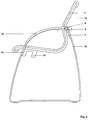
- Fig. 1
- the side view of a chair according to the invention with a vibrating frame,
- Fig. 2
- the side view of a chair according to the invention with a sled frame,
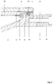
- Fig. 3
- the construction of the multifunctional knot at the rear crossbeam,
- Fig. 4
- a perspective view of the seating from obliquely behind,
- Fig. 5
- the structure of the suspension of the rear dome of the stand frame of the seating furniture according to Fig.1 on the front crossmember, and
- Fig. 6
- an alternative for the execution of the profile rails for a different fastening of the membrane and the chair upholstery.
In Fig.1 ist die auf der linken Seite des Sitzmöbels befindliche Profilschiene 1 dargestellt, die mit ihrer korrespondierenden, in dieser Figur nicht sichtbaren Profilschiene auf der anderen Seite eine Sitzschale mit dem Stuhl-Polster 10 bildet. Das Standgestell 13 weist unten den Standteil auf, von dessen vorderem Ende der Vorderdom bogenförmig nach oben verläuft, und zunächst über den Anbindungsflansch 15 mit der vorderen Traverse 14, und dann über den Anbindungsflansch 7 mit der hinteren Traverse 2 verbunden ist. Der Hinterdom des Standgestells 13 ist im Lager 17 des Anbindungsflansches 16 drehbar an der vorderen Traverse 14 gelagert. Im Bereich der Sitzschale ist das Standgestell 13 mit Armlehnen-Auflagen 18 aus Holz belegt.
In Fig.2 ist ein prinzipiell mit der Fig.1 gleichartiges Sitzmöbel dargestellt, jedoch mit dem Unterschied, daß hier der Hinterdom des Standgestells 13 über den Anbindungsflansch 7 mit der hinteren Traverse 2 verbunden ist.
In Fig.4 ist das in Fig.2 dargestellte Sitzmöbel nochmals in Perspektive schräg von hinten dargestellt. Hier ist auch die zwischen den beiden Profilschienen 1 aufgespannte Membrane 3 zu sehen.
Beide Ausführungsformen der Erfindung haben wegen der Verwendung gebogener Aluminium-Profile ein geringes Gewicht und sind kostengünstig herzustellen.
Die Ausführungsform nach Fig.1, also mit einem Schwinger-Standgestell, hat eine ergonomisch vorteilhafte Schwingcharakteristik. Diese Charakteristik wird insbesondere durch die drehbare Lagerung des oberen Endes des Hinterdoms des Standgestells 13 und die Flexibilität dieses Hinterdoms bestimmt, der bei Belastung des Sitzmöbels durch das Benutzer-Gewicht nach oben auslenkt.
Die Ausführungsform nach Fig.2, also mit einem Kufen-Standgestell, hat eine Gestellflexibilität in der Längsachse und eine gute Querstabilität, welche durch die Querschnitte der verwendeten Aluminium-Profile bestimmt sind.
In Fig.3 ist der Aufbau des multifunktionalen Knotens bei der hinteren Traverse 2 dargestellt. Diese ist mit dem Standgestell-Anbindungsflansch 7 mittels der Schraube 9 verbunden, die in der Schraubenkopfaufnahme 8 ruht. Die Profilschiene 1 ist mit der Traverse 2 über die Schraube 6 verschraubt. Die Membran 3 ist über den Keder 4 in der Nut 5 fixiert. Das Polster 10 weist ein als Keder 11 wirkendes Kunststoffteil mit einer Nase auf, das in die Nut 12 eingreift.
Wie aus den Figuren 1 und 2 ersichtlich, kann der Anbindungsflansch 7 ein- oder zweiarmig ausgebildet sein. In der einarmigen Ausführungsform wird er im Schwinger-, in der zweiarmigen Ausführung wird er im Kufen-Modell verwendet.
In Fig.5 ist schließlich noch die Anbindung des Hinterdoms des Standgestells 13 im Bereich der vorderen Traverse 14 beim Schwinger-Modell gemäß Fig. 1 dargestellt:
Sowohl der Traversen-Anbindungsflansch 15 als auch der Standgestell-Anbindungsflansch 16 weisen jeweils eine Lager-Bohrung auf, durch welche der Lager-Bolzen 17 geführt ist.
Die Flansche 15 und 16 sind mit Hinter- bzw. Vorderdom des Standgestells 13 wie ersichtlich über jeweils zwei Schrauben verschraubt.
In Fig. 6 ist eine alternative Form der Profilschienen 1 und der Befestigung der Membran 3 und des Stuhl-Polsters 10 dargestellt:
Membran-Nut 5 und Polster-Nut 12 liegen - im Gegensatz zu der in Fig. 3 dargestellten Ausführungsform - nebeneinander, und die Membran 3 ist um die die Nut 5 oben abschließende Nase herumgeführt. Diese Ausführung ist weitgehend äquivalent zu der in Fig. 3 gezeigten.
Ein wesentlicher Unterschied besteht jedoch bei der Befestigung des Stuhl-Polsters 10: Dieses weist eine sich über die ganze Seitenkante erstreckende Befestigungsfahne 19 auf, die mittels des Keders 11 in der Nut 12 gehalten wird.
Die Befestigungsfahne 19 besteht aus einem Textilvlies, das - wie durch die beiden senkrechten Striche in der Zeichnung angedeutet - mit dem Polster 10 vernäht ist. Das Kederteil 11 besteht aus Polypropylen, was gegenüber PVC den Vorteil der vollständigen Recyclierbarkeit hat.
An der Ober- und der Unter-Kante (siehe z.B. Fig. 1) wird das Polster 10 vorzugsweise mit horizontal verlaufenden Taschen versehen, in die U-förmige Klammern z.B. aus Federstahl eingesetzt werden. Sodann wird das Polster 10 umgekippt und mittels der Klammern an der Profil-Schiene 1 befestigt.
Diese Ausführungsform gewährleistet nicht nur einen festen Sitz des Polsters 10, sondern eröffnet auch die Möglichkeit, die Polster 10 in einfacher Weise im fest montierten Stuhl einzusetzen oder daraus zu entfernen, beispielsweise zwecks Nachrüstung oder Austausch des Polsters.
Wie ersichtlich, sind Sitzmöbel nach der Erfindung nicht nur kostengünstig herzustellen, sondern auch bei Lieferung und Gebrauch hoch flexibel handhabbar.
Die Membrane 3 ist in ergonomisch vorteilhafter Weise im Sitzhöckerbereich weniger elastisch ausgelegt als im Lehnenbereich und im Oberschenkelbereich.1 shows the
In FIG. 2, seating furniture that is basically the same as FIG. 1 is shown, but with the difference that here the rear dome of the
In Figure 4 the seating furniture shown in Figure 2 is shown again in perspective obliquely from behind. Here you can also see the
Both embodiments of the invention are lightweight due to the use of curved aluminum profiles and are inexpensive to manufacture.
The embodiment according to FIG. 1, that is to say with an oscillating stand frame, has an ergonomically advantageous oscillating characteristic. This characteristic is determined in particular by the rotatable mounting of the upper end of the rear dome of the
The embodiment according to FIG. 2, that is to say with a skid standing frame, has a frame flexibility in the longitudinal axis and good transverse stability, which are determined by the cross sections of the aluminum profiles used.
3 shows the structure of the multifunctional knot in the
As can be seen from FIGS. 1 and 2, the connecting
Finally, FIG. 5 shows the connection of the rear dome of the
Both the
The
6 shows an alternative form of the profile rails 1 and the fastening of the
In contrast to the embodiment shown in FIG. 3, the
However, there is an essential difference in the attachment of the chair upholstery 10: This has an
The
At the top and bottom edges (see, for example, FIG. 1), the
This embodiment not only ensures that the
As can be seen, seating furniture according to the invention is not only inexpensive to manufacture, but can also be handled in a highly flexible manner during delivery and use.
The
- 11
- ProfilschienenProfile rails
- 22nd
- Traverse (hinten)Traverse (rear)
- 33rd
- Membranmembrane
- 44th
- Membran-KederMembrane piping
- 55
- Membran-NutMembrane groove
- 66
- erste Schraubefirst screw
- 77
- Standgestell-Anbindungsflansch (hinten)Stand mounting flange (rear)
- 88th
- SchraubenkopfaufnahmeScrew head mount
- 99
- zweite Schraubesecond screw
- 1010th
- Stuhl-PolsterChair upholstery
- 1111
- Polster-KederUpholstery piping
- 1212th
- Polster-NutUpholstery groove
- 1313
- StandgestellStand frame
- 1414
- Traverse (vorn)Traverse (front)
- 1515
- Traversen-Anbindungsflansch (vorn)Truss connection flange (front)
- 1616
- Standgestell-Anbindungsflansch (vorn)Stand mounting flange (front)
- 1717th
- axialer Lager-Bolzenaxial bearing bolt
- 1818th
- Armlehnen-AuflageArmrest pad
- 1919th
- BefestigungsfahneFastening flag
Claims (10)
dadurch gekennzeichnet, daß
characterized in that
Applications Claiming Priority (2)
| Application Number | Priority Date | Filing Date | Title |
|---|---|---|---|
| DE19544210A DE19544210A1 (en) | 1995-11-28 | 1995-11-28 | Seating with two side rails |
| DE19544210 | 1995-11-28 |
Publications (2)
| Publication Number | Publication Date |
|---|---|
| EP0776621A1 true EP0776621A1 (en) | 1997-06-04 |
| EP0776621B1 EP0776621B1 (en) | 2001-04-04 |
Family
ID=7778551
Family Applications (1)
| Application Number | Title | Priority Date | Filing Date |
|---|---|---|---|
| EP96115790A Expired - Lifetime EP0776621B1 (en) | 1995-11-28 | 1996-10-02 | Chair with two lateral profiled rails |
Country Status (4)
| Country | Link |
|---|---|
| EP (1) | EP0776621B1 (en) |
| AT (1) | ATE200197T1 (en) |
| DE (2) | DE19544210A1 (en) |
| ES (1) | ES2156608T3 (en) |
Cited By (3)
| Publication number | Priority date | Publication date | Assignee | Title |
|---|---|---|---|---|
| EP0965480A3 (en) * | 1998-06-16 | 2000-06-14 | Euromotive Gesellschaft m.b.H. | Backrest construction |
| WO2007121516A1 (en) * | 2006-04-20 | 2007-11-01 | Ues (Int'l) Pty Ltd | Membrane support for seating |
| US7416251B2 (en) | 2005-06-10 | 2008-08-26 | Global Total Office | Chair |
Citations (3)
| Publication number | Priority date | Publication date | Assignee | Title |
|---|---|---|---|---|
| US3431022A (en) * | 1967-05-29 | 1969-03-04 | Steelcase Inc | Chair construction |
| EP0247385A2 (en) * | 1986-05-23 | 1987-12-02 | VS Vereinigte Spezialmöbelfabriken Verwaltungs-GmbH | Seating furniture, particularly a chair |
| US5318348A (en) * | 1991-11-19 | 1994-06-07 | Winston Furniture Company, Inc. | Cushioned sling chair |
Family Cites Families (12)
| Publication number | Priority date | Publication date | Assignee | Title |
|---|---|---|---|---|
| DE7342881U (en) * | 1974-05-30 | Winkler O Kg | chair | |
| US3498668A (en) * | 1968-01-29 | 1970-03-03 | Telescope Folding Furniture Co | Seat for a captain's chair |
| DE1945583C3 (en) * | 1968-11-21 | 1974-02-07 | Expo-Nord Ab, Hoerby (Schweden) | Seating or reclining furniture with a support part for supporting the human body |
| GB1493112A (en) * | 1974-03-28 | 1977-11-23 | Cox T Ltd | Trim lock |
| DE7735346U1 (en) * | 1977-11-18 | 1978-03-09 | Peter Lancier Maschinenbau-Hafenhuette Gmbh & Co Kg, 4400 Muenster | CABLE LOOP CHAIR WITH REMOVABLE SEAT CLOTH |
| DE3207352A1 (en) * | 1982-03-02 | 1983-09-08 | Wilkhahn Wilkening + Hahne GmbH + Co, 3252 Bad Münder | ARMCHAIR |
| DE8509395U1 (en) * | 1985-03-29 | 1985-06-27 | benze collection Sitzmöbelwerk GmbH & Co KG, 3252 Bad Münder | Fastening device for fixing a flexible covering on a support frame for seating furniture or the like. |
| US4938530A (en) * | 1988-01-27 | 1990-07-03 | Steelcase, Inc. | Wire frame chair |
| DE8900957U1 (en) * | 1989-01-28 | 1989-03-09 | Tillner, Alfred, 4513 Belm, De | |
| DE3921970A1 (en) * | 1989-07-04 | 1991-01-17 | Knoll International | See=saw action chair - has one piece seat and back with curved elastic legs supported by hinged elements and rotates about axis through hinge |
| DE8911050U1 (en) * | 1989-09-15 | 1989-11-09 | Tillner, Alfred, 4513 Belm, De | |
| DE4033972A1 (en) * | 1990-10-25 | 1992-04-30 | Buerositzmoebelfabrik Friedric | Free swinging chair on frame - has pivot mounted back rest, with pivot axle and seat, with slide guide containing bolt in slide bearing |
-
1995
- 1995-11-28 DE DE19544210A patent/DE19544210A1/en not_active Withdrawn
-
1996
- 1996-10-02 DE DE59606706T patent/DE59606706D1/en not_active Expired - Fee Related
- 1996-10-02 ES ES96115790T patent/ES2156608T3/en not_active Expired - Lifetime
- 1996-10-02 EP EP96115790A patent/EP0776621B1/en not_active Expired - Lifetime
- 1996-10-02 AT AT96115790T patent/ATE200197T1/en not_active IP Right Cessation
Patent Citations (3)
| Publication number | Priority date | Publication date | Assignee | Title |
|---|---|---|---|---|
| US3431022A (en) * | 1967-05-29 | 1969-03-04 | Steelcase Inc | Chair construction |
| EP0247385A2 (en) * | 1986-05-23 | 1987-12-02 | VS Vereinigte Spezialmöbelfabriken Verwaltungs-GmbH | Seating furniture, particularly a chair |
| US5318348A (en) * | 1991-11-19 | 1994-06-07 | Winston Furniture Company, Inc. | Cushioned sling chair |
Cited By (5)
| Publication number | Priority date | Publication date | Assignee | Title |
|---|---|---|---|---|
| EP0965480A3 (en) * | 1998-06-16 | 2000-06-14 | Euromotive Gesellschaft m.b.H. | Backrest construction |
| US6761412B1 (en) | 1998-06-16 | 2004-07-13 | Euromotive Ges. M.B.H. | Backrest construction |
| US7416251B2 (en) | 2005-06-10 | 2008-08-26 | Global Total Office | Chair |
| WO2007121516A1 (en) * | 2006-04-20 | 2007-11-01 | Ues (Int'l) Pty Ltd | Membrane support for seating |
| AU2007242055B2 (en) * | 2006-04-20 | 2011-06-02 | Ues (Int'l) Pty Ltd | Membrane support for seating |
Also Published As
| Publication number | Publication date |
|---|---|
| EP0776621B1 (en) | 2001-04-04 |
| DE19544210A1 (en) | 1997-06-05 |
| ES2156608T3 (en) | 2001-07-01 |
| DE59606706D1 (en) | 2001-05-10 |
| ATE200197T1 (en) | 2001-04-15 |
Similar Documents
| Publication | Publication Date | Title |
|---|---|---|
| DE19750116C2 (en) | Adjustment mechanism for the lateral support areas of a seat, in particular of its backrest | |
| EP1849378B1 (en) | Device for attaching a backrest | |
| DE2353341C3 (en) | Stackable sled-base chair with a frame made of metal tubes or profiles | |
| DE102006030018A1 (en) | Backrest for a chair or armchair and chair or armchair equipped with such a backrest | |
| DE19637933C1 (en) | Frame for sitting or crouching on | |
| DE3329581A1 (en) | SEAT FURNITURE WITH SYNCHRONOUS BACKREST AND SEAT MOVEMENT | |
| DE69917697T2 (en) | Rocking and sliding mechanism | |
| EP0993794B1 (en) | Chair, especially office chair | |
| DE2343566C3 (en) | Row chair with folding seat | |
| EP0246474A2 (en) | Seating furniture, particularly a chair | |
| EP0776621B1 (en) | Chair with two lateral profiled rails | |
| DE19526437C2 (en) | Chair, especially a row chair | |
| DE102007057620A1 (en) | Folding Chair | |
| DE4137488A1 (en) | Chair with concave backrest - has material weak spot forming swivel axis level with bend | |
| DE3130885A1 (en) | Chair made of tubular steel | |
| DE102009056762B4 (en) | Chair with a bookcase | |
| EP0479046B1 (en) | Stackable seating furniture | |
| DE4428244A1 (en) | Chair connectable into row of seats | |
| DE4016687A1 (en) | Ergonomic layout of rear seats of vehicle - with provision for varying seat angles about axis | |
| DE2421970A1 (en) | Adaptable lightweight, easily produced seat unit - comprises two frames fitted with different coverings and paddings | |
| DE1945705C (en) | armchair | |
| DE1258740B (en) | Seat for vehicles, especially airplanes | |
| WO2000021416A1 (en) | Seating furniture | |
| DE1554090A1 (en) | Metal or steel seating | |
| EP0984872B1 (en) | Support for the back of a seat, specially an automobile seat |
Legal Events
| Date | Code | Title | Description |
|---|---|---|---|
| PUAI | Public reference made under article 153(3) epc to a published international application that has entered the european phase |
Free format text: ORIGINAL CODE: 0009012 |
|
| AK | Designated contracting states |
Kind code of ref document: A1 Designated state(s): AT CH DE ES FR GB IT LI NL |
|
| 17P | Request for examination filed |
Effective date: 19970728 |
|
| GRAG | Despatch of communication of intention to grant |
Free format text: ORIGINAL CODE: EPIDOS AGRA |
|
| GRAG | Despatch of communication of intention to grant |
Free format text: ORIGINAL CODE: EPIDOS AGRA |
|
| GRAH | Despatch of communication of intention to grant a patent |
Free format text: ORIGINAL CODE: EPIDOS IGRA |
|
| 17Q | First examination report despatched |
Effective date: 20000704 |
|
| GRAH | Despatch of communication of intention to grant a patent |
Free format text: ORIGINAL CODE: EPIDOS IGRA |
|
| GRAA | (expected) grant |
Free format text: ORIGINAL CODE: 0009210 |
|
| AK | Designated contracting states |
Kind code of ref document: B1 Designated state(s): AT CH DE ES FR GB IT LI NL |
|
| REF | Corresponds to: |
Ref document number: 200197 Country of ref document: AT Date of ref document: 20010415 Kind code of ref document: T |
|
| REG | Reference to a national code |
Ref country code: CH Ref legal event code: EP |
|
| REF | Corresponds to: |
Ref document number: 59606706 Country of ref document: DE Date of ref document: 20010510 |
|
| ITF | It: translation for a ep patent filed |
Owner name: DE DOMINICIS & MAYER S.R.L. |
|
| ET | Fr: translation filed | ||
| REG | Reference to a national code |
Ref country code: ES Ref legal event code: FG2A Ref document number: 2156608 Country of ref document: ES Kind code of ref document: T3 |
|
| GBT | Gb: translation of ep patent filed (gb section 77(6)(a)/1977) |
Effective date: 20010607 |
|
| REG | Reference to a national code |
Ref country code: GB Ref legal event code: IF02 |
|
| PLBE | No opposition filed within time limit |
Free format text: ORIGINAL CODE: 0009261 |
|
| STAA | Information on the status of an ep patent application or granted ep patent |
Free format text: STATUS: NO OPPOSITION FILED WITHIN TIME LIMIT |
|
| 26N | No opposition filed | ||
| PGFP | Annual fee paid to national office [announced via postgrant information from national office to epo] |
Ref country code: GB Payment date: 20030929 Year of fee payment: 8 |
|
| PGFP | Annual fee paid to national office [announced via postgrant information from national office to epo] |
Ref country code: NL Payment date: 20030930 Year of fee payment: 8 |
|
| PGFP | Annual fee paid to national office [announced via postgrant information from national office to epo] |
Ref country code: CH Payment date: 20031001 Year of fee payment: 8 Ref country code: AT Payment date: 20031001 Year of fee payment: 8 |
|
| PGFP | Annual fee paid to national office [announced via postgrant information from national office to epo] |
Ref country code: FR Payment date: 20031009 Year of fee payment: 8 |
|
| PGFP | Annual fee paid to national office [announced via postgrant information from national office to epo] |
Ref country code: DE Payment date: 20031010 Year of fee payment: 8 |
|
| PGFP | Annual fee paid to national office [announced via postgrant information from national office to epo] |
Ref country code: ES Payment date: 20031020 Year of fee payment: 8 |
|
| PG25 | Lapsed in a contracting state [announced via postgrant information from national office to epo] |
Ref country code: GB Free format text: LAPSE BECAUSE OF NON-PAYMENT OF DUE FEES Effective date: 20041002 Ref country code: AT Free format text: LAPSE BECAUSE OF NON-PAYMENT OF DUE FEES Effective date: 20041002 |
|
| PG25 | Lapsed in a contracting state [announced via postgrant information from national office to epo] |
Ref country code: ES Free format text: LAPSE BECAUSE OF NON-PAYMENT OF DUE FEES Effective date: 20041004 |
|
| PG25 | Lapsed in a contracting state [announced via postgrant information from national office to epo] |
Ref country code: LI Free format text: LAPSE BECAUSE OF NON-PAYMENT OF DUE FEES Effective date: 20041031 Ref country code: CH Free format text: LAPSE BECAUSE OF NON-PAYMENT OF DUE FEES Effective date: 20041031 |
|
| PG25 | Lapsed in a contracting state [announced via postgrant information from national office to epo] |
Ref country code: NL Free format text: LAPSE BECAUSE OF NON-PAYMENT OF DUE FEES Effective date: 20050501 |
|
| PG25 | Lapsed in a contracting state [announced via postgrant information from national office to epo] |
Ref country code: DE Free format text: LAPSE BECAUSE OF NON-PAYMENT OF DUE FEES Effective date: 20050503 |
|
| GBPC | Gb: european patent ceased through non-payment of renewal fee |
Effective date: 20041002 |
|
| REG | Reference to a national code |
Ref country code: CH Ref legal event code: PL |
|
| PG25 | Lapsed in a contracting state [announced via postgrant information from national office to epo] |
Ref country code: FR Free format text: LAPSE BECAUSE OF NON-PAYMENT OF DUE FEES Effective date: 20050630 |
|
| NLV4 | Nl: lapsed or anulled due to non-payment of the annual fee |
Effective date: 20050501 |
|
| REG | Reference to a national code |
Ref country code: FR Ref legal event code: ST |
|
| PG25 | Lapsed in a contracting state [announced via postgrant information from national office to epo] |
Ref country code: IT Free format text: LAPSE BECAUSE OF NON-PAYMENT OF DUE FEES;WARNING: LAPSES OF ITALIAN PATENTS WITH EFFECTIVE DATE BEFORE 2007 MAY HAVE OCCURRED AT ANY TIME BEFORE 2007. THE CORRECT EFFECTIVE DATE MAY BE DIFFERENT FROM THE ONE RECORDED. Effective date: 20051002 |
|
| REG | Reference to a national code |
Ref country code: ES Ref legal event code: FD2A Effective date: 20041004 |