EP0776552B1 - Fehlerortung in optischen übertragungssystemen - Google Patents
Fehlerortung in optischen übertragungssystemen Download PDFInfo
- Publication number
- EP0776552B1 EP0776552B1 EP95927893A EP95927893A EP0776552B1 EP 0776552 B1 EP0776552 B1 EP 0776552B1 EP 95927893 A EP95927893 A EP 95927893A EP 95927893 A EP95927893 A EP 95927893A EP 0776552 B1 EP0776552 B1 EP 0776552B1
- Authority
- EP
- European Patent Office
- Prior art keywords
- upstream
- data sequence
- sequence
- downstream
- data
- Prior art date
- Legal status (The legal status is an assumption and is not a legal conclusion. Google has not performed a legal analysis and makes no representation as to the accuracy of the status listed.)
- Expired - Lifetime
Links
Images


Classifications
-
- H—ELECTRICITY
- H04—ELECTRIC COMMUNICATION TECHNIQUE
- H04B—TRANSMISSION
- H04B10/00—Transmission systems employing electromagnetic waves other than radio-waves, e.g. infrared, visible or ultraviolet light, or employing corpuscular radiation, e.g. quantum communication
- H04B10/07—Arrangements for monitoring or testing transmission systems; Arrangements for fault measurement of transmission systems
-
- G—PHYSICS
- G01—MEASURING; TESTING
- G01M—TESTING STATIC OR DYNAMIC BALANCE OF MACHINES OR STRUCTURES; TESTING OF STRUCTURES OR APPARATUS, NOT OTHERWISE PROVIDED FOR
- G01M11/00—Testing of optical apparatus; Testing structures by optical methods not otherwise provided for
- G01M11/30—Testing of optical devices, constituted by fibre optics or optical waveguides
- G01M11/31—Testing of optical devices, constituted by fibre optics or optical waveguides with a light emitter and a light receiver being disposed at the same side of a fibre or waveguide end-face, e.g. reflectometers
- G01M11/3109—Reflectometers detecting the back-scattered light in the time-domain, e.g. OTDR
- G01M11/3118—Reflectometers detecting the back-scattered light in the time-domain, e.g. OTDR using coded light-pulse sequences
-
- G—PHYSICS
- G01—MEASURING; TESTING
- G01M—TESTING STATIC OR DYNAMIC BALANCE OF MACHINES OR STRUCTURES; TESTING OF STRUCTURES OR APPARATUS, NOT OTHERWISE PROVIDED FOR
- G01M11/00—Testing of optical apparatus; Testing structures by optical methods not otherwise provided for
- G01M11/30—Testing of optical devices, constituted by fibre optics or optical waveguides
- G01M11/31—Testing of optical devices, constituted by fibre optics or optical waveguides with a light emitter and a light receiver being disposed at the same side of a fibre or waveguide end-face, e.g. reflectometers
- G01M11/3109—Reflectometers detecting the back-scattered light in the time-domain, e.g. OTDR
- G01M11/3136—Reflectometers detecting the back-scattered light in the time-domain, e.g. OTDR for testing of multiple fibers
-
- H—ELECTRICITY
- H04—ELECTRIC COMMUNICATION TECHNIQUE
- H04B—TRANSMISSION
- H04B10/00—Transmission systems employing electromagnetic waves other than radio-waves, e.g. infrared, visible or ultraviolet light, or employing corpuscular radiation, e.g. quantum communication
- H04B10/07—Arrangements for monitoring or testing transmission systems; Arrangements for fault measurement of transmission systems
- H04B10/071—Arrangements for monitoring or testing transmission systems; Arrangements for fault measurement of transmission systems using a reflected signal, e.g. using optical time domain reflectometers [OTDR]
-
- H—ELECTRICITY
- H04—ELECTRIC COMMUNICATION TECHNIQUE
- H04B—TRANSMISSION
- H04B10/00—Transmission systems employing electromagnetic waves other than radio-waves, e.g. infrared, visible or ultraviolet light, or employing corpuscular radiation, e.g. quantum communication
- H04B10/27—Arrangements for networking
- H04B10/272—Star-type networks or tree-type networks
Definitions
- This invention relates to optical communications systems and in particular to the provision of time domain reflectometry to effect fault detection and location in such systems.
- Optical time domain reflectometry is a well known technique used to determine the location of discontinuities in the impedance of a transmission medium (e.g.. optical fibre wave guide, coaxial cable) by the measurement of the amplitude and delay of reflections of a travelling wave generated by the discontinuities.
- a transmission medium e.g.. optical fibre wave guide, coaxial cable
- OTDR Optical time domain reflectometry
- a description of OTDR is given in IEEE Journal of lightwave technology, Vol. 17 No. 8 August 89, pp1217 to 1224, and in specification No. WO-93/07687.
- This technique has been used to locate faults and breakages in the transmission medium.
- the travelling wave is generated by a short impulse, the amplitude, rise time and width of which combined with the bandwidth of the transmission medium and sensitivity of the reflection detection process determine the performance (resolution) of the method.
- time domain reflectometry employs separate test equipment and requires a means of coupling this shared equipment into the access fibres.
- PON passive optical network
- the object of the invention is to minimise or to overcome this disadvantage.
- an optical communications system including a data transmitter, a data receiver, and incorporating a time domain reflectometry fault location arrangement, the system including means for transmitting a downstream data sequence having statistical properties equivalent to a continuous random binary sequence, means for generating an upstream data sequence orthogonal to the downstream data sequence, and means for generating a time delayed copy of the downstream data sequence, characterised in that said upstream sequence has quiet periods containing no data, and that the system has means for correlating said time delayed copy during said quiet period with an echo of the downstream data sequence reflected from a fault, and means for adjusting said time delay whereby to achieve said correlation and to determine the location of said fault.
- a method of fault location in an optical communications system including transmitting a downstream data sequence having statistical properties equivalent to a continuous random binary sequence, generating an upstream data sequence orthogonal to the downstream data sequence, generating a time delayed copy of the downstream data sequence, characterised in that said upstream sequence has quiet periods containing no data, and that said time delayed copy is correlated in said quiet period with an echo of the downstream data sequence reflected from a fault whereby to determine the location of said fault.
- the transmitted data itself is used as test sequence.
- the receiver is provided with the ability to detect reflections using either (i) a correlation window noise tracking algorithm or (ii) by de-composition requiring the subtraction of an estimate of the transmitter primary interference path.
- a passive optical ranging method is employed to produce a system capable of detecting the loop delay of discontinuities in the fibre and hence determining cable breaks inferred by significant changes in the reflection of information.
- the pseudo random sequence may be launched at a level below that which would otherwise affect the error free detection of normal data transmission.
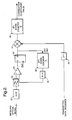
- the transmission system includes a data transmitter unit 1 containing a data sequence formatter 2, an optical transmitter 3 and an associated controller 4.
- the data transmitter unit is coupled via a fibre 5 to a passive optical splitter 6 and through a further fibre path 7 and data receiver unit 8.
- the data receiving unit comprises an optical receiver 9 with its controller 10 and a data re-formatter 11, providing data re-formatting as required for the next stage in the data path.
- the optical splitter allows optical signals to be combined and separated using optical wave guides, and has the additional property that the optical signal coupling is directional so that backward reflections due to the splitter itself, are typically one tenth or less in amplitude in comparison with the forward travelling light, this property applying to both transmission directions.
- a data receiver unit 13 On the upstream side of the system, a data receiver unit 13 is placed on a second fibre 18 connected to the left hand side of the splitter allowing it to see reflections from output ports of the splitter and fibre network to the right of the splitter (and any other upstream data source).
- This receiver signal processing unit contains an optical receiver 14, a controller 15, a signal processor block 17 and may also contain a data re-formatter block 16.
- the data transmitter unit 1 sequence source formatter contains a data scrambler 19 which scrambles the data such that the downstream transmitted data sequence has statistical properties equivalent to those of a continuous random binary sequence. This allows the transmitted data itself to be used in the correlation process, this transmitted data being orthogonal to the upstream data which is also randomised.
- An upstream data formatter 21 which contains the same functions as the data transmitter unit 1 may transmit an upstream data sequence that leaves a segment, i.e.
- one or more time slots, of the upstream frame unused or reserved specifically to provide a quiet period in which the data receiver unit 13 can calculate the correlation coefficient between a delayed version of the transmitted data sequence from the transmitter unit 1 and potential reflections of it arising from discontinuities in the fibre at the splitter or to the downstream side of the splitter.
- this original processing function includes an optical to electrical conversion function 32 which converts the optical input signal into a voltage proportional to the optical power.
- a DC balancing circuit comprising a comparator 34, a digital to analogue converter 35, a first up/down counter 36 and a D-type flip-flop 37. which adjusts the threshold level of the D/A comparator converter 35 to a value resulting in a substantially equal number of ones and zeros.
- This circuit is only active during that part of the frame in which there is no signal other than reflections from the fibre discontinuities, consequently the noise level of the receiver will in practice be of greater amplitude than the signals reflected.
- the product of the data sequence is formed by the digital multiplier 41 from the data sequence delayed by n clock cycles and the digitised data output from D-type flip-flop 37 and is integrated using an up down counter 39).
- the output of the up down counter 39 gives the correlation between the signal received as the upstream fibre and the downstream transmitted signal and hence directly allow measurement of reflections with a resolution approximately equal to one bit at the data clock rate.
- the up-down counter used to drive the D to A converter has a step size that is a fraction of the D/A resolution (for example one sixteenth) in order that wander of the threshold value due to random noise does not dominate the decision process.
- the noise level with no signal will be greater than the reflections due to cable discontinuities.
- Figure 1 shows how a receiver unit may be configured to provide the means for calculation of the amplitude of upstream reflections from the downstream signal path.
- this unit is then serving no purpose other than time domain reflectometry.
- Further receiver units may be added on the downstream side of the splitter to produce a simplex point to multipoint system and a separate fibre network provided for upstream.
- the directional properties of the splitter may be sufficient to provide for duplex transmission in which case the receiver unit may be used both for time domain reflectometry and data reception and data transmitter units 21 employed.
- this shows a further reflectometry arrangement.
- the transmitted data is used as the test signal.
- the reflectometer is coupled to an optical transmission path 41 on either side of a bidirectional amplifier 42 using the four port taps 43a, 43b that are provided for monitoring the amplifier performance.
- the taps remove about 5% of the power being transmitted along the fibre path.
- signals are present, in different optical wavelength bands, in the forward and reverse directions.
- a four port tap is provided at both ends of the amplifier to monitor the input and output signals, and to perform analogue maintenance in both directions. The reflection measurement calculations can then be done in both directions.
- interference can be produced in the reflection array.
- Known correlations such as the SONET frame patterns, can be eliminated by zeroing those frequency components.
- Other signals may require more complex compensation using all four data arrays, or even the maintenance procedure of removing or changing one signal to prove that the result is not an artefact of signal correlation. Changing one signal e.g. to SONET AIS would eliminate its data content and break the uncompensated correlations.
- the output ports of the taps 43a, 43b are coupled each to a respective photodetector, e.g. a PIN diode 44a, 44b, 44c and 44d.
- the currents from the PIN photo diodes are amplified and band limited ( ⁇ 0 to 5 MHz) by respective transimpedance amplifiers 46a, 46b, 46c and 46d whose outputs are coupled each to a respective fast analogue to digital converter 47a-47d.
- the output signals from the respective analogue to digital converters are referred to below as the r1, s1, r2 and s2 signals.
- the fast typically about 10 MHz, analogue to digital converters 47 simultaneously sample the levels of the outgoing and incoming optical signals and pass the resulting arrays of data to a signal processor 48 whereby the Fast Fourier transforms of the signals are computed, divided, and then Inverse Fast Fourier Transformed to produce a reflection array.
- the elements of this array r(n) correspond each to the reflection from a location at a distance n * ⁇ L down the fibre, plus noise and interference.
- the largest reflections can be compared to thresholds, e.g. to generate alarms, and can be displayed to the user via the transmission system's software.
- the dominant noise term is the locally generated thermal noise.
- Improved sensitivity is achieved by lengthening the time span of the stimulus signal.
- the resolution of the distance is inversely proportional to the bandwidth of the stimulus signal. For a bandwidth of 5 MHz and assuming Nyquist sampling, a resolution of about 20 metres can be achieved.
- the spatial resolution can be improved by faster sampling or by phase correlation signal processing techniques to resolve better than one sampling interval. Note that this resolution depends on an acceptable autocorrelation function for the particular stimulus signal. This autocorrelation function can be computed as a check for the acceptability of the particular s(t) as a stimulus signal.
- the noise depends upon the amount of signal variation in the relevant frequency band (0-5 MHz) and the amount of averaging or filtering done to the results.
- the dither that is applied for analogue maintenance helps to ensure that there is low frequency content.
- the resolution of the distance depends upon the sampling frequency. For example, a sampling frequency of 10 MHz produces a ⁇ L of 100 ns divided by 5 ns/m, equivalent to a 20 m round trip, or 10 meters one way.
- the spatial resolution can be improved by faster sampling or by phase correlation signal processing techniques to resolve better than one sampling interval.
- Known reflections such as those originating from within the amplifier can be calibrated in the factory, and then dynamically calculated as a function of the amplifier gain and subtracted off.
- Another interference compensation method is to examine the spectrums F ⁇ b ⁇ an F ⁇ c ⁇ , and zero or attenuate F ⁇ b ⁇ at those frequencies where F ⁇ c ⁇ is above a predetermined threshold relative to F ⁇ b ⁇ . This reduces the number of components that may interfere.
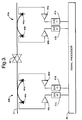
- FIG. 4 A further development allowing simplex operation combined with time domain reflectometry is shown in figure 4.
- two splitters 51, 52
- a path 58 is provided for reflections from the downstream path to enter one leg of the upstream path. This will incur attenuation dependent on the upstream splitter loss and this could be increased as necessary to ensure that under no circumstances would a reflection from the downstream path compromise the performance of the upstream path.
- reflections from the upstream path can enter the downstream path in the same way via path 59, but will be equally attenuated.
- Reflections in the upstream path to the left of the splitter in figure 4 may be determined using the same method as described employing one of the downstream optical receiver units and a downstream marshalling technique e.g.. as described in our specification No GB-A-2272608. In this case the data captured in this window would be correlated with the data received at the upstream receiver unit on the upstream side of the diagram to move all processing functions to the upstream side forming the head end of a passive optical network system.
- a second method is to introduce a path between the downstream and upstream splitter in which by virtue of the downstream splitter loss (typically 15 dB for a 32 way splitter), any attenuated remnant of the downstream data is transmitted towards the transmitter units on one downstream side of the diagram.
- the downstream splitter loss typically 15 dB for a 32 way splitter
- any attenuated remnant of the downstream data is transmitted towards the transmitter units on one downstream side of the diagram.
- reflections from any discontinuity between the splitter and one downstream side optical transmitter units will pass back through the upstream splitter and arrive at the data receiver unit 55 (and the standby data receiver unit). Additional attenuation could be placed in the inter coupler path in order to eliminate the downstream signal on the upstream fibres compromising the performance of the transmitters (63, 64, 65) or the possibility of reflections from this being large enough to compromise the receiver performance (55, 56).
- a dedicated test transmitter (59) (Fig. 3) could be used to provide a TDR mechanism in which case, in order to avoid interference with the upstream path, operation of this test transmitter in a very low power mode could be used.
- adaptive coefficients can be used to eliminate the received signal components, thus providing effectively a decision directed equaliser where the residue is used as the correlator input to determine reflection coefficients, adaptation may employ the well known gradient estimation algorithm.
Landscapes
- Physics & Mathematics (AREA)
- Engineering & Computer Science (AREA)
- Electromagnetism (AREA)
- Computer Networks & Wireless Communication (AREA)
- Signal Processing (AREA)
- Optics & Photonics (AREA)
- Chemical & Material Sciences (AREA)
- Analytical Chemistry (AREA)
- General Physics & Mathematics (AREA)
- Computing Systems (AREA)
- Optical Communication System (AREA)
Claims (7)
- Optisches Kommunikationssystem, das einen Datensender (1, 21), einen Datenempfänger (8, 13) einschließt und eine Rückstreumeßtechnik-Fehlerortungsanordnung beinhaltet, wobei das System Einrichtungen (2) zur Aussendung einer Abwärtsrichtungs-Datenfolge mit statistischen Eigenschaften, die zu einer kontinuierlichen binären Zufallsfolge äquivalent sind, Einrichtungen (21) zur Erzeugung einer Aufwärtsrichtungs-Datenfolge orthogonal zu der Abwärtsrichtungs-Datenfolge und Einrichtungen (40) zur Erzeugung einer zeitverzögerten Kopie der Abwärtsrichtungs-Datenfolge einschließt, dadurch gekennzeichnet, daß die Aufwärtsrichtungs-Folge Ruheperioden aufweist, die keine Daten enthalten, und daß das System eine Einrichtung (13) zur Korrelation der zeitverzögerten Kopie während der Ruheperiode mit einem Echo der Abwärtsrichtungs-Datenfolge, die von einem Fehler reflektiert wird, und eine Einrichtung zur Einstellung der Zeitverzögerung aufweist, wodurch die Korrelation erzielt wird und der Ort des Fehlers bestimmt wird.
- Optisches Kommunikationssystem nach Anspruch 1, dadurch gekennzeichnet, daß die Korrelationseinrichtung einen digitalen Multiplizierer (41) aufweist, dessen Ausgang mit einem Aufwärts-/Abwärts-Zähler (39) gekoppelt ist, wodurch eine Zählung geschaffen wird, die die Korrelation anzeigt.
- Optisches Kommunikationssystem nach Anspruch 1, dadurch gekennzeichnet, daß das System Verstärkerstationen (42) beinhaltet, und bei dem die Fehlerortungsanordnung mit dem System über ein oder mehrere Anzapfungen (43a, 43b) gekoppelt ist, die an einer Verstärkerstation vorgesehen sind.
- Optisches Kommunikationssystem nach Anspruch 3, dadurch gekennzeichnet, daß die Korrelationseinrichtung Einrichtungen (48) zur Bestimmung der schnellen Fourier-Transformationen der Aufwärtsrichtungs- und Abwärtsrichtungs-Signale, Einrichtungen zur Bestimmung des Verhältnisses der Transformationen und Einrichtungen zur Bestimmung der inversen Transformation des Verhältnisses einschließt, wodurch eine Reflexionsmatrix erzeugt wird.
- Optisches Kommunikationssystem nach einem der Ansprüche 1-4, das ein passives optisches Netz aufweist.
- Verfahren zur Fehlerortung in einem optischen Kommunikationssystem, wobei das Verfahren die Aussendung einer Abwärtsrichtungs-Datenfolge mit statistischen Eigenschaften, die einer kontinuierlichen binären Zufallsfolge äquivalent sind, die Erzeugung einer Aufwärtsrichtungs-Datenfolge orthogonal zu der Abwärtsrichtungs-Datenfolge und die Erzeugung einer zeitverzögerten Kopie der Abwärtsrichtungs-Datenfolge einschließt, dadurch gekennzeichnet, daß die Aufwärtsrichtungs-Folge Ruheperioden aufweist, die keine Daten enthalten, und daß die zeitverzögerte Kopie in der Ruheperiode mit einem Echo der Abwärtsrichtungs-Datenfolge korreliert wird, die von einem Fehler reflektiert wird, wodurch der Ort des Fehlers bestimmt wird.
- Verfahren nach Anspruch 6, dadurch gekennzeichnet, daß die Korrelation durch Bestimmen der schnellen Fourier-Transformationen der Aufwärtsrichtungs- und Abwärtsrichtungs-Signale, durch Bestimmen des Verhältnisses der Transformationen und durch Bestimmen der inversen Transformation des Verhältnisses bewirkt wird, wodurch eine Reflexionsmatrix erzeugt wird.
Applications Claiming Priority (3)
| Application Number | Priority Date | Filing Date | Title |
|---|---|---|---|
| GB9416661 | 1994-08-17 | ||
| GB9416661A GB2292495B (en) | 1994-08-17 | 1994-08-17 | Fault location in optical communication systems |
| PCT/GB1995/001918 WO1996005665A1 (en) | 1994-08-17 | 1995-08-15 | Fault location in optical communication systems |
Publications (2)
| Publication Number | Publication Date |
|---|---|
| EP0776552A1 EP0776552A1 (de) | 1997-06-04 |
| EP0776552B1 true EP0776552B1 (de) | 2001-01-24 |
Family
ID=10760008
Family Applications (1)
| Application Number | Title | Priority Date | Filing Date |
|---|---|---|---|
| EP95927893A Expired - Lifetime EP0776552B1 (de) | 1994-08-17 | 1995-08-15 | Fehlerortung in optischen übertragungssystemen |
Country Status (5)
| Country | Link |
|---|---|
| US (1) | US6075628A (de) |
| EP (1) | EP0776552B1 (de) |
| DE (1) | DE69519990T2 (de) |
| GB (1) | GB2292495B (de) |
| WO (1) | WO1996005665A1 (de) |
Families Citing this family (84)
| Publication number | Priority date | Publication date | Assignee | Title |
|---|---|---|---|---|
| GB9526185D0 (en) * | 1995-12-21 | 1996-02-21 | Stc Submarine Systems Ltd | Fiber-break detection in bi-directional optical amplifier systems |
| IT1283522B1 (it) * | 1996-07-26 | 1998-04-21 | Italtel Spa | Inserimento ed estrazione di un terzo canale o banda su una fibra ottica portante due canali o bande ottiche mediante un singolo |
| SE506320C2 (sv) * | 1996-09-23 | 1997-12-01 | Ericsson Telefon Ab L M | Förfarande och anordning för att detektera fel i ett nätverk |
| US5926263A (en) * | 1996-10-10 | 1999-07-20 | Tyco Submarine Systems Ltd. | Side-tone OTDR for in-service optical cable monitoring |
| US5898801A (en) | 1998-01-29 | 1999-04-27 | Lockheed Martin Corporation | Optical transport system |
| US5999258A (en) * | 1997-06-26 | 1999-12-07 | Nortel Networks Corporation | Optical interference measurement method and system |
| US6072614A (en) * | 1997-08-21 | 2000-06-06 | Nortel Networks Corporation | Monitoring induced counterpropagating signals in optical communications systems |
| AU2338099A (en) * | 1998-01-23 | 1999-08-09 | Trilithic, Inc. | Testing of catv systems |
| US6687632B1 (en) | 1998-01-23 | 2004-02-03 | Trilithic, Inc. | Testing of CATV systems |
| US6166850A (en) * | 1998-11-04 | 2000-12-26 | Nortel Networks Limited | Optical amplifier gain control |
| GB2348063B (en) * | 1999-03-19 | 2001-03-07 | Marconi Comm Ltd | Optical communication system |
| JP3440886B2 (ja) * | 1999-06-16 | 2003-08-25 | 日本電気株式会社 | 波長多重光伝送システム |
| CA2294555A1 (en) | 1999-12-30 | 2001-06-30 | Nortel Networks Corporation | Optimization of a communications system based on identification of an optical medium |
| US7184670B2 (en) * | 2000-05-10 | 2007-02-27 | Lockheed Martin Corporation | Telemetry system and method for acoustic arrays |
| US7072588B2 (en) * | 2000-10-03 | 2006-07-04 | Halliburton Energy Services, Inc. | Multiplexed distribution of optical power |
| US20020101874A1 (en) * | 2000-11-21 | 2002-08-01 | Whittaker G. Allan | Physical layer transparent transport information encapsulation methods and systems |
| US6829293B2 (en) | 2001-01-16 | 2004-12-07 | Mindspeed Technologies, Inc. | Method and apparatus for line probe signal processing |
| US6898214B1 (en) * | 2001-03-09 | 2005-05-24 | Lucent Technologies Inc. | Technique for monitoring SONET signal |
| US6947857B2 (en) * | 2001-03-16 | 2005-09-20 | Mindspeed Technologies, Inc. | Optical sequence time domain reflectometry during data transmission |
| US6934655B2 (en) * | 2001-03-16 | 2005-08-23 | Mindspeed Technologies, Inc. | Method and apparatus for transmission line analysis |
| US6885954B2 (en) * | 2001-03-16 | 2005-04-26 | Mindspeed Technologies, Inc. | Sequence time domain reflectometry using complementary golay codes |
| US20030035376A1 (en) * | 2001-08-20 | 2003-02-20 | Xiaofen Chen | Derivation of composite step-function response |
| DE10140852C5 (de) * | 2001-08-21 | 2016-11-17 | Robert Bosch Gmbh | Elektronisches System mit einem Lichtwellenleiter-Netzwerk und Verfahren zum Selbsttest sowie dazugehöriges Computerprogramm |
| US7079764B2 (en) * | 2001-08-27 | 2006-07-18 | Ross Saunders | Fault isolation technique for optical networks |
| US20030068024A1 (en) * | 2001-10-05 | 2003-04-10 | Jones William W. | Communication system activation |
| US7146101B2 (en) * | 2001-11-08 | 2006-12-05 | Altera Corporation | Optical media management channel |
| US20040208507A1 (en) * | 2002-01-21 | 2004-10-21 | Ross Saunders | Network diagnostic tool for an optical transport network |
| US7242862B2 (en) * | 2002-01-21 | 2007-07-10 | Altera Corporation | Network diagnostic tool for an optical transport network |
| US7085497B2 (en) | 2002-04-03 | 2006-08-01 | Lockheed Martin Corporation | Vehicular communication system |
| US7187713B2 (en) * | 2002-05-29 | 2007-03-06 | Mindspeed Technologies, Inc. | Method and apparatus for intelligent modem warm start |
| US7099581B2 (en) * | 2002-08-20 | 2006-08-29 | Red Sky Subsea Ltd. | OTDR arrangement for detecting faults in an optical transmission system on a span by span basis |
| US20040076434A1 (en) * | 2002-09-27 | 2004-04-22 | Whittaker G. Allan | Optical distribution network for RF and other analog signals |
| US6912339B2 (en) * | 2002-09-27 | 2005-06-28 | Lockheed Martin Corporation | Optical interface devices having balanced amplification |
| US7283480B1 (en) | 2002-11-12 | 2007-10-16 | Lockheed Martin Corporation | Network system health monitoring using cantor set signals |
| US7349629B1 (en) | 2002-11-26 | 2008-03-25 | Lockheed Martin Corporation | Methods and systems for creating a digital interconnect fabric |
| DE10307542A1 (de) * | 2002-11-27 | 2004-06-17 | Fibotec Fiberoptics Gmbh | Verfahren und Anordnung zur Ermittlung von Verluststellen in optischen Fasern |
| US6842586B2 (en) * | 2003-01-23 | 2005-01-11 | Red Sky Systems, Inc. | OTDR arrangement for detecting faults in an optical transmission system employing two pairs of unidirectional optical fibers |
| US7424228B1 (en) | 2003-03-31 | 2008-09-09 | Lockheed Martin Corporation | High dynamic range radio frequency to optical link |
| WO2004093351A2 (en) * | 2003-03-31 | 2004-10-28 | Lockheed Martin Corporation | Optical network interface systems and devices |
| US9337948B2 (en) | 2003-06-10 | 2016-05-10 | Alexander I. Soto | System and method for performing high-speed communications over fiber optical networks |
| GB0322859D0 (en) * | 2003-09-30 | 2003-10-29 | British Telecomm | Communication |
| US7667849B2 (en) * | 2003-09-30 | 2010-02-23 | British Telecommunications Public Limited Company | Optical sensor with interferometer for sensing external physical disturbance of optical communications link |
| US7460498B2 (en) * | 2003-12-04 | 2008-12-02 | Adtran, Inc. | System and method for detecting anomalies along telecommunication lines |
| WO2005069883A2 (en) * | 2004-01-15 | 2005-08-04 | Bae Systems Information And Electronic Systems Integration Inc. | Method and apparatus for transmission line and waveguide testing |
| GB0407386D0 (en) * | 2004-03-31 | 2004-05-05 | British Telecomm | Monitoring a communications link |
| US7440699B1 (en) | 2004-06-28 | 2008-10-21 | Lockheed Martin Corporation | Systems, devices and methods for transmitting and receiving signals on an optical network |
| US7848645B2 (en) * | 2004-09-30 | 2010-12-07 | British Telecommunications Public Limited Company | Identifying or locating waveguides |
| GB0421747D0 (en) * | 2004-09-30 | 2004-11-03 | British Telecomm | Distributed backscattering |
| US8045174B2 (en) | 2004-12-17 | 2011-10-25 | British Telecommunications Public Limited Company | Assessing a network |
| GB0427733D0 (en) * | 2004-12-17 | 2005-01-19 | British Telecomm | Optical system |
| GB0504579D0 (en) * | 2005-03-04 | 2005-04-13 | British Telecomm | Communications system |
| DE602006007442D1 (de) * | 2005-03-04 | 2009-08-06 | British Telecomm Public Ltd Co | Akustooptische modulatoranordnung |
| EP1708388A1 (de) | 2005-03-31 | 2006-10-04 | British Telecommunications Public Limited Company | Verfahren zum Mitteilen von Informationen |
| EP1867973A1 (de) * | 2005-04-08 | 2007-12-19 | Eisai R&D Management Co., Ltd. | Probennahmevorrichtung für zähflüssige probe, homogenisierungsverfahren für sputum und mikrobennachweisverfahren |
| EP1713301A1 (de) * | 2005-04-14 | 2006-10-18 | BRITISH TELECOMMUNICATIONS public limited company | Verfahren und Gerät zur Schallübertragung über eine optische Verbindung |
| EP1729096A1 (de) * | 2005-06-02 | 2006-12-06 | BRITISH TELECOMMUNICATIONS public limited company | Verfahren und Vorrichtung zur Ermittlung der Stelle einer Störung in einer optischen Faser |
| EP1753159B1 (de) * | 2005-08-12 | 2007-12-19 | Alcatel Lucent | Verfahren und Vorrichtung zur Überwachung einer optischen Verbindung und optischer Sender mit einer solchen Vorrichtung |
| EP1826924A1 (de) * | 2006-02-24 | 2007-08-29 | BRITISH TELECOMMUNICATIONS public limited company | Abtastung einer Störung |
| WO2007096578A1 (en) * | 2006-02-24 | 2007-08-30 | British Telecommunications Public Limited Company | Sensing a disturbance |
| WO2007096579A1 (en) * | 2006-02-24 | 2007-08-30 | British Telecommunications Public Limited Company | Sensing a disturbance |
| CA2647173A1 (en) * | 2006-04-03 | 2007-10-11 | British Telecommunications Public Company Limited | Evaluating the position of a disturbance |
| DE602007004951D1 (de) * | 2007-04-26 | 2010-04-08 | Alcatel Lucent | Optisches Netzwerk, Überwachungseinheit und Überwachungsverfahren |
| US8750341B2 (en) | 2008-01-04 | 2014-06-10 | Mindspeed Technologies, Inc. | Method and apparatus for reducing optical signal speckle |
| CN101257346B (zh) * | 2008-04-02 | 2012-12-12 | 华为技术有限公司 | 获取光路故障位置的方法、装置和系统 |
| US8461848B2 (en) | 2008-12-10 | 2013-06-11 | Marvell International Ltd. | Cable diagnostics for Base-T systems |
| US8855491B2 (en) | 2008-12-30 | 2014-10-07 | Broadcom Corporation | Techniques for protecting passive optical networks |
| US8873960B2 (en) | 2008-12-30 | 2014-10-28 | Broadcom Corporation | Techniques for detecting optical faults in passive optical networks |
| US8874391B2 (en) * | 2009-06-05 | 2014-10-28 | Bae Systems Information And Electronic Systems Integration Inc. | Distance-to-fault measurement system capable of measuring complex reflection coefficients |
| EP2273708B1 (de) * | 2009-06-30 | 2013-06-05 | Alcatel Lucent | System und Verfahren zur Übertragung optischer Signale |
| US8606117B1 (en) * | 2010-05-20 | 2013-12-10 | Adtran, Inc. | Systems and methods for unobtrusively testing optical fibers |
| US8964172B1 (en) * | 2010-09-27 | 2015-02-24 | Rockwell Collins, Inc. | Means to detect damage in composite material panels |
| US20130077961A1 (en) * | 2011-09-27 | 2013-03-28 | Broadlight, Ltd. | Techniques for generating low rate data patterns compliant with passive optical networks |
| CN103326775B (zh) * | 2012-03-22 | 2017-02-01 | 中兴通讯股份有限公司 | 光网络故障在线检测方法及装置 |
| WO2015006623A1 (en) * | 2013-07-10 | 2015-01-15 | Neophotonics Corporation | Optical network communication system with embedded optical time domain reflectometer and method of operation thereof |
| US9438335B2 (en) * | 2013-12-26 | 2016-09-06 | Texas Instruments Incorporated | Optical fiber defect detection |
| EP3577799B1 (de) * | 2017-02-01 | 2023-08-30 | British Telecommunications public limited company | Faseroptische ereignisortung |
| CN111051843B (zh) | 2017-07-20 | 2022-03-18 | 英国电讯有限公司 | 光纤 |
| US10911052B2 (en) | 2018-05-23 | 2021-02-02 | Macom Technology Solutions Holdings, Inc. | Multi-level signal clock and data recovery |
| US11005573B2 (en) | 2018-11-20 | 2021-05-11 | Macom Technology Solutions Holdings, Inc. | Optic signal receiver with dynamic control |
| US12013423B2 (en) | 2020-09-30 | 2024-06-18 | Macom Technology Solutions Holdings, Inc. | TIA bandwidth testing system and method |
| US11658630B2 (en) | 2020-12-04 | 2023-05-23 | Macom Technology Solutions Holdings, Inc. | Single servo loop controlling an automatic gain control and current sourcing mechanism |
| US20220247488A1 (en) * | 2021-02-02 | 2022-08-04 | Huawei Technologies Co., Ltd. | Method and system inspecting fibered optical communication paths |
| CN114172565B (zh) * | 2021-12-03 | 2023-05-23 | 上海橙科微电子科技有限公司 | 信道质量检测方法及系统 |
| US12191862B2 (en) | 2021-12-24 | 2025-01-07 | Macom Technology Solutions Holdings, Inc. | Hybrid phase-interpolator |
Family Cites Families (14)
| Publication number | Priority date | Publication date | Assignee | Title |
|---|---|---|---|---|
| GB2190186B (en) * | 1986-05-09 | 1990-12-19 | Dr Jeremy Kenneth Arth Everard | Greatly enhanced spatial detection of optical backscatter for sensor applications |
| GB8828408D0 (en) * | 1988-12-06 | 1989-01-05 | British Telecomm | Loss detector |
| EP0379609B1 (de) * | 1989-01-24 | 1993-07-28 | Hewlett-Packard GmbH | Verfahren und Vorrichtung zum Anwenden von optischen Zeitbereichsreflektometern |
| DE3920169A1 (de) * | 1989-06-16 | 1990-12-20 | Siemens Ag | Einrichtung und verfahren zur untersuchung des daempfungsverlaufs eines lichtwellenleiters |
| CA2031870C (en) * | 1989-12-11 | 1995-08-08 | Nobuo Tomita | Device and a method for distinguishing faults employed in an optical transmission system |
| GB9027716D0 (en) * | 1990-12-20 | 1991-02-13 | British Telecomm | Optical communications system |
| JPH04225130A (ja) * | 1990-12-27 | 1992-08-14 | Anritsu Corp | 光伝送装置 |
| GB9115453D0 (en) * | 1991-07-18 | 1991-09-04 | British Telecomm | Fault location in optical systems |
| GB9121226D0 (en) * | 1991-10-04 | 1991-11-20 | British Telecomm | Monitoring system |
| US5321541A (en) * | 1991-12-12 | 1994-06-14 | At&T Bell Laboratories | Passive optical communication network with broadband upgrade |
| GB9202564D0 (en) * | 1992-02-07 | 1992-03-25 | Marconi Gec Ltd | Optical signal transmission network |
| GB2272608B (en) * | 1992-11-12 | 1996-10-09 | Northern Telecom Ltd | Telecommunications systems |
| NL9301903A (nl) * | 1993-11-04 | 1995-06-01 | Nederland Ptt | Plaatsonafhankelijke toepassing van een op correlatie gebaseerde OTDR-techniek in een vertakt optische vezel-netwerk in bedrijf. |
| US5859716A (en) * | 1996-01-18 | 1999-01-12 | Northern Telecom Limited | Self-stimulation signal detection in an optical transmission system |
-
1994
- 1994-08-17 GB GB9416661A patent/GB2292495B/en not_active Expired - Fee Related
-
1995
- 1995-08-15 EP EP95927893A patent/EP0776552B1/de not_active Expired - Lifetime
- 1995-08-15 WO PCT/GB1995/001918 patent/WO1996005665A1/en not_active Ceased
- 1995-08-15 US US08/793,629 patent/US6075628A/en not_active Expired - Lifetime
- 1995-08-15 DE DE69519990T patent/DE69519990T2/de not_active Expired - Fee Related
Also Published As
| Publication number | Publication date |
|---|---|
| GB9416661D0 (en) | 1994-10-12 |
| US6075628A (en) | 2000-06-13 |
| GB2292495A (en) | 1996-02-21 |
| DE69519990T2 (de) | 2001-05-03 |
| EP0776552A1 (de) | 1997-06-04 |
| GB2292495B (en) | 1998-03-25 |
| DE69519990D1 (de) | 2001-03-01 |
| WO1996005665A1 (en) | 1996-02-22 |
Similar Documents
| Publication | Publication Date | Title |
|---|---|---|
| EP0776552B1 (de) | Fehlerortung in optischen übertragungssystemen | |
| US6947857B2 (en) | Optical sequence time domain reflectometry during data transmission | |
| US6708004B1 (en) | Method and apparatus for reducing crosstalk between a monitoring channel and a data channel in a WDM optical communication system | |
| US7088436B2 (en) | Integrated optical time domain reflectometer and optical supervisory network | |
| CA2267777C (en) | Monitoring system using an optical side tone as a test signal | |
| US5416623A (en) | Optical communications system | |
| JP4183699B2 (ja) | 光分配ネットワーク監視方法およびシステム | |
| US20190323921A1 (en) | High Resolution Correlation Optical Time Domain Reflectometer | |
| JP2875114B2 (ja) | 光伝送システム | |
| US20040019443A1 (en) | Sequence time domain reflectometry using complementary golay codes | |
| WO2005086780A2 (en) | Cotdr arrangement with swept frequency pulse generator for an optical transmission system | |
| JPH06268598A (ja) | 光通信監視システムおよび方法 | |
| CA2496206A1 (en) | Adaptor arrangement for detecting faults in an optically amplified multi-span transmission system using a remotely located otdr | |
| EP1023587A1 (de) | Optischer reflektometer unter verwendung des optischen rückhörnsignal im zeitbereich für die betriebsüberwachung von optischen kabeln | |
| CA2114729C (en) | Network with line monitoring system | |
| CA2496237A1 (en) | Otdr arrangement for detecting faults in an optical transmission system on a span by span basis | |
| KR101053057B1 (ko) | 광 전송 시스템의 인서비스 모니터링 방법 및 장치 | |
| GB2413447A (en) | Short pulse loop back supervisory system | |
| Lipovac et al. | Otdr based estimation of co-ofdm cfo | |
| CN114650096B (zh) | 光路自适应色散补偿方法、光模块和波分复用系统 | |
| CA2552711A1 (en) | Method and apparatus for obtaining status information concerning optical amplifiers located along an undersea optical transmission line using cotdr | |
| WO2005086779A2 (en) | Method and apparatus for obtaining status information concerning an in-service optical transmission line | |
| CA2552578A1 (en) | Method and apparatus for in-service monitoring of a regional undersea optical transmission system using cotdr | |
| GB2267792A (en) | Fault location in optical communications system | |
| EP4427361A1 (de) | Verzögerungsmessung für faseroptische verbindung |
Legal Events
| Date | Code | Title | Description |
|---|---|---|---|
| PUAI | Public reference made under article 153(3) epc to a published international application that has entered the european phase |
Free format text: ORIGINAL CODE: 0009012 |
|
| 17P | Request for examination filed |
Effective date: 19970317 |
|
| AK | Designated contracting states |
Kind code of ref document: A1 Designated state(s): DE FR GB |
|
| 17Q | First examination report despatched |
Effective date: 19980305 |
|
| RAP3 | Party data changed (applicant data changed or rights of an application transferred) |
Owner name: NORTEL NETWORKS CORPORATION |
|
| GRAG | Despatch of communication of intention to grant |
Free format text: ORIGINAL CODE: EPIDOS AGRA |
|
| GRAG | Despatch of communication of intention to grant |
Free format text: ORIGINAL CODE: EPIDOS AGRA |
|
| GRAH | Despatch of communication of intention to grant a patent |
Free format text: ORIGINAL CODE: EPIDOS IGRA |
|
| RAP1 | Party data changed (applicant data changed or rights of an application transferred) |
Owner name: NORTEL NETWORKS LIMITED |
|
| GRAH | Despatch of communication of intention to grant a patent |
Free format text: ORIGINAL CODE: EPIDOS IGRA |
|
| GRAA | (expected) grant |
Free format text: ORIGINAL CODE: 0009210 |
|
| AK | Designated contracting states |
Kind code of ref document: B1 Designated state(s): DE FR GB |
|
| REF | Corresponds to: |
Ref document number: 69519990 Country of ref document: DE Date of ref document: 20010301 |
|
| ET | Fr: translation filed | ||
| PLBE | No opposition filed within time limit |
Free format text: ORIGINAL CODE: 0009261 |
|
| STAA | Information on the status of an ep patent application or granted ep patent |
Free format text: STATUS: NO OPPOSITION FILED WITHIN TIME LIMIT |
|
| REG | Reference to a national code |
Ref country code: GB Ref legal event code: IF02 |
|
| 26N | No opposition filed | ||
| PGFP | Annual fee paid to national office [announced via postgrant information from national office to epo] |
Ref country code: GB Payment date: 20040721 Year of fee payment: 10 |
|
| PGFP | Annual fee paid to national office [announced via postgrant information from national office to epo] |
Ref country code: FR Payment date: 20040804 Year of fee payment: 10 |
|
| PGFP | Annual fee paid to national office [announced via postgrant information from national office to epo] |
Ref country code: DE Payment date: 20040831 Year of fee payment: 10 |
|
| PG25 | Lapsed in a contracting state [announced via postgrant information from national office to epo] |
Ref country code: GB Free format text: LAPSE BECAUSE OF NON-PAYMENT OF DUE FEES Effective date: 20050815 |
|
| PG25 | Lapsed in a contracting state [announced via postgrant information from national office to epo] |
Ref country code: DE Free format text: LAPSE BECAUSE OF NON-PAYMENT OF DUE FEES Effective date: 20060301 |
|
| GBPC | Gb: european patent ceased through non-payment of renewal fee |
Effective date: 20050815 |
|
| PG25 | Lapsed in a contracting state [announced via postgrant information from national office to epo] |
Ref country code: FR Free format text: LAPSE BECAUSE OF NON-PAYMENT OF DUE FEES Effective date: 20060428 |
|
| REG | Reference to a national code |
Ref country code: FR Ref legal event code: ST Effective date: 20060428 |