EP0776537B1 - Dispositif de commande ou de signalisation electrique muni d'un bloc amovible - Google Patents
Dispositif de commande ou de signalisation electrique muni d'un bloc amovible Download PDFInfo
- Publication number
- EP0776537B1 EP0776537B1 EP96922936A EP96922936A EP0776537B1 EP 0776537 B1 EP0776537 B1 EP 0776537B1 EP 96922936 A EP96922936 A EP 96922936A EP 96922936 A EP96922936 A EP 96922936A EP 0776537 B1 EP0776537 B1 EP 0776537B1
- Authority
- EP
- European Patent Office
- Prior art keywords
- electrical unit
- fixing
- fact
- baseplate
- base
- Prior art date
- Legal status (The legal status is an assumption and is not a legal conclusion. Google has not performed a legal analysis and makes no representation as to the accuracy of the status listed.)
- Expired - Lifetime
Links
Images

Classifications
-
- H—ELECTRICITY
- H02—GENERATION; CONVERSION OR DISTRIBUTION OF ELECTRIC POWER
- H02B—BOARDS, SUBSTATIONS OR SWITCHING ARRANGEMENTS FOR THE SUPPLY OR DISTRIBUTION OF ELECTRIC POWER
- H02B11/00—Switchgear having carriage withdrawable for isolation
-
- H—ELECTRICITY
- H02—GENERATION; CONVERSION OR DISTRIBUTION OF ELECTRIC POWER
- H02B—BOARDS, SUBSTATIONS OR SWITCHING ARRANGEMENTS FOR THE SUPPLY OR DISTRIBUTION OF ELECTRIC POWER
- H02B1/00—Frameworks, boards, panels, desks, casings; Details of substations or switching arrangements
- H02B1/015—Boards, panels, desks; Parts thereof or accessories therefor
- H02B1/04—Mounting thereon of switches or of other devices in general, the switch or device having, or being without, casing
- H02B1/044—Mounting through openings
-
- H—ELECTRICITY
- H02—GENERATION; CONVERSION OR DISTRIBUTION OF ELECTRIC POWER
- H02B—BOARDS, SUBSTATIONS OR SWITCHING ARRANGEMENTS FOR THE SUPPLY OR DISTRIBUTION OF ELECTRIC POWER
- H02B1/00—Frameworks, boards, panels, desks, casings; Details of substations or switching arrangements
- H02B1/015—Boards, panels, desks; Parts thereof or accessories therefor
- H02B1/04—Mounting thereon of switches or of other devices in general, the switch or device having, or being without, casing
Definitions
- the present invention relates to a device for controlling or electrical signaling such as a push button comprising a body to be engaged in a hole in a wall and an electrical block, in particular a contact block, as well a carrier base attached to the body on the back of the wall and provided with removable fixing means for the electrical block.
- Removable attachment of the electrical block to the carrier base must be carried out reliably and sustainably. It is already known, for example from document DE-24 46 912, to provide two elastic tabs that snap onto the electrical block in lateral notches of the base, but the fixing thus obtained is not strong enough. It is also known to fix the contact block to the base by means of a single screw; the fixing is then resistant and can be carried out fairly quickly, but the prior positioning of the block is not satisfactory.
- the object of the invention is to give the fixing of an electrical block under a base of a control or signaling device of the type described above great strength, while reducing the assembly time of the device.
- the electrical unit comprises, on its fixing face located towards the carrier base, on one side a fixing screw cooperating with a tapped hole from the base and on the opposite side a rigid heel for positioning and holding engaged in a step of complementary shape formed in the base.
- the introduction of the rigid heel into the step allows the operator to preposition with restraint one side of the electrical block on the base before tighten the screw on the other side.
- the electrical blocks are advantageously stackable and present Indeed, on their connection face which is located opposite the base, a threaded element and a step similar to those of the base to receive the fixing screw and respectively the rigid heel of a stacked block.
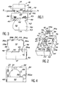
- the electrical control or signaling device illustrated on the Figures is a push button comprising a body 10 provided with a head 11 and a tubular part 12 of axis X1 and of diameter less than the width of the head. This is posed with possibly a seal and / or a label not shown on one side external 13a of a thin support wall 13, for example metallic, which belongs to an envelope such as a lectern, a cabinet, ...
- the wall 13 is oriented according to a plane S and includes an orifice 13b in which the tubular part 12 engages with play of the push button, this part comprising for example the movable tail of push of the button.
- a base 20 with a general polygonal outline, preferably rectangular, is associated with the push button on the back of the wall 13, i.e. on the inner side of the wall 13, for removably carrying removable electrical blocks 30 such as switch contact blocks, indicator blocks or blocks auxiliaries.
- the base is placed on the tubular part 12 and is made therefrom secured by form elements cooperating with each other, for example by interlocking or snap-fastening, to prevent extraction of the base in the direction X1.
- the base 20 offers a central opening 21 for the free passage of the tubular part 12 of the push button and it is on the other hand anchored against the face internal 13c of the wall 13 by means of an attachment slide 22 urged by a operating screw located in a housing 22a of axis X'1 parallel to X1.
- the contact block 30 includes a prismatic housing 31 in material insulator having on the base side a fixing face 32 and on the opposite side a connection face 33 for access to a tool, via orifices 34a, 34b formed in this face 33, with screws or other connection elements 35 for wiring conductors to be inserted laterally.
- Drivers can be introduced by orifices 36a, 36b formed in small lateral faces 37a, 37b housing; it finally has large lateral faces 38,39.
- the base 20 is made of metallic or plastic material; she is scheduled for wear several contact blocks 30 side by side, three in number or more.
- each block 30 has a screw on its fixing face 32 on one side fixing 40 of axis X2 inclined with respect to X1 and cooperating with a hole 23 directly tapped in the base if it is metallic, or belonging to a metal insert if the base is made of plastic; the block on its face binding 32 and on the other side a rigid heel 41 which is hung in a step 24 of complementary shape provided in the base and which is applied against a shoulder 24a of this step so as to resist the forces communicated to the block of contacts by the push button along the thrust axis X1.
- the three tapped holes 23 are provided on a small side of the base and the three steps 24 on the small opposite side of the base.
- a movable finger 42 of block 30 protrudes from its fixing face 32 to cooperate with the movable part of the push button;
- a pin or a rigid positioning rib 43 is provided on the face fixing 32 of the contact block near the screw 40 to cooperate with a hole or a positioning slot 25 of the base and to thus contribute, after installation from the heel in the step, to correctly position the screw.
- the fixing screw 40 is accessible by a cutaway 44 formed in the small side face 37a of the housing 31.
- a withdrawal 45 which cooperates with guide ears 26 and holding belonging to the base; these ears are protruding downwards and have an inclined edge 27 whose external face extends the large walls side of the base.
- the block 30 On its connection face 33, the block 30 has on one side an orifice 50 in which is housed an insert 51 such as a nut or a part with a threaded pin hole oblique parallel to X2 to receive the fixing screw 40 of a block 60 stacked on the block 30.
- the nut 51 plays the same role as the tapped hole 23 of the base 20.
- the block 30 From on the other side, the block 30 has an orifice 52 provided with a step 53 with a shoulder of retainer 53a similar to the step 24 of the base 20 to become the rigid heel 41 of the block 60.
- the orifices 50, 52 may be distinct from the orifices 34a, 34b, the screws 35, they are preferably common with these orifices as indicated on the Figures 5 and 6.
- the pin or the rib 43 located on the fixing face 32 of the underlying block 60 cooperates with a hole or a slot 54 formed in the face of connection 33 of the contact block 30.
- Interlocking shapes 28 can be provided under the base 20 (see FIG. 5) between the tapped holes 23 to guide and fit the corresponding side of the fixing face 32 of the blocks 30.
Landscapes
- Engineering & Computer Science (AREA)
- Power Engineering (AREA)
- Push-Button Switches (AREA)
- Switch Cases, Indication, And Locking (AREA)
- Patch Boards (AREA)
- Connector Housings Or Holding Contact Members (AREA)
- Casings For Electric Apparatus (AREA)
Applications Claiming Priority (3)
| Application Number | Priority Date | Filing Date | Title |
|---|---|---|---|
| FR9507462 | 1995-06-20 | ||
| FR9507462A FR2735943B1 (fr) | 1995-06-20 | 1995-06-20 | Dispositif de commande ou de signalisation electrique muni d'un bloc amovible |
| PCT/FR1996/000928 WO1997001205A1 (fr) | 1995-06-20 | 1996-06-17 | Dispositif de commande ou de signalisation electrique muni d'un bloc amovible |
Publications (2)
| Publication Number | Publication Date |
|---|---|
| EP0776537A1 EP0776537A1 (fr) | 1997-06-04 |
| EP0776537B1 true EP0776537B1 (fr) | 1999-08-18 |
Family
ID=9480252
Family Applications (1)
| Application Number | Title | Priority Date | Filing Date |
|---|---|---|---|
| EP96922936A Expired - Lifetime EP0776537B1 (fr) | 1995-06-20 | 1996-06-17 | Dispositif de commande ou de signalisation electrique muni d'un bloc amovible |
Country Status (13)
| Country | Link |
|---|---|
| US (1) | US5772476A (cs) |
| EP (1) | EP0776537B1 (cs) |
| JP (1) | JPH10505480A (cs) |
| KR (1) | KR970705859A (cs) |
| CN (1) | CN1051650C (cs) |
| AU (1) | AU6362496A (cs) |
| BR (1) | BR9606475A (cs) |
| CZ (1) | CZ50497A3 (cs) |
| DE (1) | DE69603819T2 (cs) |
| ES (1) | ES2135241T3 (cs) |
| FR (1) | FR2735943B1 (cs) |
| TR (1) | TR199700139T1 (cs) |
| WO (1) | WO1997001205A1 (cs) |
Families Citing this family (2)
| Publication number | Priority date | Publication date | Assignee | Title |
|---|---|---|---|---|
| FR3079973B1 (fr) * | 2018-04-10 | 2020-03-06 | Schneider Electric Industries Sas | Dispositif de fixation d'un organe de commande et/ou de signalisation |
| EP3828910A1 (en) * | 2019-11-26 | 2021-06-02 | Schneider Electric Industries SAS | Control and/or signaling component |
Family Cites Families (5)
| Publication number | Priority date | Publication date | Assignee | Title |
|---|---|---|---|---|
| US3054979A (en) * | 1958-12-03 | 1962-09-18 | Amp Inc | Multiple electrical connector |
| GB882850A (en) * | 1959-05-27 | 1961-11-22 | Controls Co Of America | Improvements in and relating to snap action electrical switches and a process for making the switches |
| US3001170A (en) * | 1959-07-20 | 1961-09-19 | Amp Inc | Electrical connecting device |
| DE2446912C3 (de) * | 1974-10-01 | 1978-12-07 | Elektro-Apparatebau Olten Ag, Olten, Solothurn (Schweiz) | Elektrische Baueinheit zum Montieren in einer elektrischen Anlage |
| CN2183623Y (zh) * | 1993-12-09 | 1994-11-23 | 杨山虎 | 插接式配电盘结构 |
-
1995
- 1995-06-20 FR FR9507462A patent/FR2735943B1/fr not_active Expired - Fee Related
-
1996
- 1996-06-17 ES ES96922936T patent/ES2135241T3/es not_active Expired - Lifetime
- 1996-06-17 DE DE69603819T patent/DE69603819T2/de not_active Expired - Fee Related
- 1996-06-17 JP JP9503613A patent/JPH10505480A/ja active Pending
- 1996-06-17 CN CN96190929A patent/CN1051650C/zh not_active Expired - Fee Related
- 1996-06-17 CZ CZ97504A patent/CZ50497A3/cs unknown
- 1996-06-17 WO PCT/FR1996/000928 patent/WO1997001205A1/fr not_active Ceased
- 1996-06-17 EP EP96922936A patent/EP0776537B1/fr not_active Expired - Lifetime
- 1996-06-17 BR BR9606475A patent/BR9606475A/pt not_active IP Right Cessation
- 1996-06-17 AU AU63624/96A patent/AU6362496A/en not_active Abandoned
- 1996-06-17 TR TR97/00139T patent/TR199700139T1/xx unknown
- 1996-06-17 KR KR1019970701032A patent/KR970705859A/ko not_active Abandoned
- 1996-06-17 US US08/776,608 patent/US5772476A/en not_active Expired - Fee Related
Also Published As
| Publication number | Publication date |
|---|---|
| AU6362496A (en) | 1997-01-22 |
| TR199700139T1 (tr) | 1997-08-21 |
| FR2735943A1 (fr) | 1996-12-27 |
| DE69603819T2 (de) | 2000-01-13 |
| WO1997001205A1 (fr) | 1997-01-09 |
| CZ50497A3 (en) | 1997-05-14 |
| KR970705859A (ko) | 1997-10-09 |
| EP0776537A1 (fr) | 1997-06-04 |
| ES2135241T3 (es) | 1999-10-16 |
| CN1051650C (zh) | 2000-04-19 |
| FR2735943B1 (fr) | 1997-08-29 |
| BR9606475A (pt) | 1997-12-23 |
| US5772476A (en) | 1998-06-30 |
| JPH10505480A (ja) | 1998-05-26 |
| DE69603819D1 (de) | 1999-09-23 |
| CN1161111A (zh) | 1997-10-01 |
Similar Documents
| Publication | Publication Date | Title |
|---|---|---|
| EP0776537B1 (fr) | Dispositif de commande ou de signalisation electrique muni d'un bloc amovible | |
| EP1411590B1 (fr) | Borne de connexion élastique | |
| FR2616616A3 (fr) | Boitier pour composants electriques et/ou electroniques | |
| EP0896387B1 (fr) | Borne à vis et bornier pour appareil électrique. | |
| FR2735945A1 (fr) | Dispositif de commande ou de signalisation electrique muni d'un bloc amovible | |
| CA2245245C (fr) | Dispositif de commande ou de signalisation tel qu'un bouton-poussoir | |
| FR2652205A1 (fr) | Dispositif de fixation rapide pour appareil electrique, et appareillage electrique correspondant. | |
| FR2766297A1 (fr) | Appareil electrique portant un support de contact fixe et une borne de raccordement | |
| FR2582866A1 (fr) | Borne de jonction de cordon d'antenne pour recepteur de television | |
| EP0552114B1 (fr) | Borne de raccordement multiple pour appareillage électrique modulaire | |
| FR2735944A1 (fr) | Dispositif de commande ou de signalisation electrique muni d'un bloc amovible | |
| EP1519445B1 (fr) | Appareil électrique comportant un boîtier isolant et une borne à connexion automatique disposée dans ledit boîtier | |
| EP0700084A1 (fr) | Dispositif de fixation de composants électroniques de puissance contre un dissipateur et procédé de montage sur un circuit imprimé | |
| EP0771484A1 (fr) | Dispositif de commande ou de signalisation electrique a embase de fixation | |
| EP1610416B1 (fr) | Appareil électrique adapté à coopérer avec un peigne de répartition horizontale | |
| EP0074061B1 (fr) | Borne modulaire de raccordement électrique | |
| WO2004068644A1 (fr) | Dispositif de raccordement électrique muni de porte-repères pouvant immobiliser des repères de tailles différentes | |
| EP3553904A1 (fr) | Dispositif de fixation d'un organe de commande et/ou de signalisation | |
| EP1241764B1 (fr) | Ensemble comportant un socle et un mécanisme, entrant dans la composition d'un appareil électrique, et présentant des moyens d'encliquetage perfectionnés du mécanisme sur le socle | |
| EP1071184B1 (fr) | Griffe d'ancrage à deux zones géographiques d'action distinctes pour mécanisme électrique | |
| FR2974681A1 (fr) | Dispositif de commande et/ou de signalisation electrique | |
| FR2730095A1 (fr) | Dispositif de connexion a auto-denudage | |
| FR2852067A1 (fr) | Borne a vis debrayable | |
| EP1187154B1 (fr) | Appareil électrique à poussoir | |
| FR2671669A1 (fr) | Connecteur electrique de mise a la masse. |
Legal Events
| Date | Code | Title | Description |
|---|---|---|---|
| PUAI | Public reference made under article 153(3) epc to a published international application that has entered the european phase |
Free format text: ORIGINAL CODE: 0009012 |
|
| 17P | Request for examination filed |
Effective date: 19970207 |
|
| AK | Designated contracting states |
Kind code of ref document: A1 Designated state(s): DE ES IT SE |
|
| GRAG | Despatch of communication of intention to grant |
Free format text: ORIGINAL CODE: EPIDOS AGRA |
|
| GRAG | Despatch of communication of intention to grant |
Free format text: ORIGINAL CODE: EPIDOS AGRA |
|
| GRAH | Despatch of communication of intention to grant a patent |
Free format text: ORIGINAL CODE: EPIDOS IGRA |
|
| 17Q | First examination report despatched |
Effective date: 19981126 |
|
| GRAH | Despatch of communication of intention to grant a patent |
Free format text: ORIGINAL CODE: EPIDOS IGRA |
|
| GRAA | (expected) grant |
Free format text: ORIGINAL CODE: 0009210 |
|
| RAP1 | Party data changed (applicant data changed or rights of an application transferred) |
Owner name: SCHNEIDER ELECTRIC INDUSTRIES SA |
|
| AK | Designated contracting states |
Kind code of ref document: B1 Designated state(s): DE ES IT SE |
|
| REF | Corresponds to: |
Ref document number: 69603819 Country of ref document: DE Date of ref document: 19990923 |
|
| REG | Reference to a national code |
Ref country code: ES Ref legal event code: FG2A Ref document number: 2135241 Country of ref document: ES Kind code of ref document: T3 |
|
| ITF | It: translation for a ep patent filed | ||
| PLBE | No opposition filed within time limit |
Free format text: ORIGINAL CODE: 0009261 |
|
| STAA | Information on the status of an ep patent application or granted ep patent |
Free format text: STATUS: NO OPPOSITION FILED WITHIN TIME LIMIT |
|
| 26N | No opposition filed | ||
| PGFP | Annual fee paid to national office [announced via postgrant information from national office to epo] |
Ref country code: DE Payment date: 20030505 Year of fee payment: 8 |
|
| PGFP | Annual fee paid to national office [announced via postgrant information from national office to epo] |
Ref country code: SE Payment date: 20030520 Year of fee payment: 8 |
|
| PGFP | Annual fee paid to national office [announced via postgrant information from national office to epo] |
Ref country code: ES Payment date: 20030612 Year of fee payment: 8 |
|
| PG25 | Lapsed in a contracting state [announced via postgrant information from national office to epo] |
Ref country code: SE Free format text: LAPSE BECAUSE OF NON-PAYMENT OF DUE FEES Effective date: 20040618 Ref country code: ES Free format text: LAPSE BECAUSE OF NON-PAYMENT OF DUE FEES Effective date: 20040618 |
|
| PG25 | Lapsed in a contracting state [announced via postgrant information from national office to epo] |
Ref country code: DE Free format text: LAPSE BECAUSE OF NON-PAYMENT OF DUE FEES Effective date: 20050101 |
|
| EUG | Se: european patent has lapsed | ||
| EUG | Se: european patent has lapsed | ||
| PG25 | Lapsed in a contracting state [announced via postgrant information from national office to epo] |
Ref country code: IT Free format text: LAPSE BECAUSE OF NON-PAYMENT OF DUE FEES;WARNING: LAPSES OF ITALIAN PATENTS WITH EFFECTIVE DATE BEFORE 2007 MAY HAVE OCCURRED AT ANY TIME BEFORE 2007. THE CORRECT EFFECTIVE DATE MAY BE DIFFERENT FROM THE ONE RECORDED. Effective date: 20050617 |
|
| REG | Reference to a national code |
Ref country code: ES Ref legal event code: FD2A Effective date: 20040618 |