EP0775656A2 - Sheet feeder and method of separating sheets - Google Patents
Sheet feeder and method of separating sheets Download PDFInfo
- Publication number
- EP0775656A2 EP0775656A2 EP96118618A EP96118618A EP0775656A2 EP 0775656 A2 EP0775656 A2 EP 0775656A2 EP 96118618 A EP96118618 A EP 96118618A EP 96118618 A EP96118618 A EP 96118618A EP 0775656 A2 EP0775656 A2 EP 0775656A2
- Authority
- EP
- European Patent Office
- Prior art keywords
- sheet
- stack
- uppermost
- sheet stack
- sheets
- Prior art date
- Legal status (The legal status is an assumption and is not a legal conclusion. Google has not performed a legal analysis and makes no representation as to the accuracy of the status listed.)
- Granted
Links
Images


Classifications
-
- B—PERFORMING OPERATIONS; TRANSPORTING
- B65—CONVEYING; PACKING; STORING; HANDLING THIN OR FILAMENTARY MATERIAL
- B65H—HANDLING THIN OR FILAMENTARY MATERIAL, e.g. SHEETS, WEBS, CABLES
- B65H3/00—Separating articles from piles
- B65H3/32—Separating articles from piles by elements, e.g. fingers, plates, rollers, inserted or traversed between articles to be separated and remainder of the pile
-
- B—PERFORMING OPERATIONS; TRANSPORTING
- B65—CONVEYING; PACKING; STORING; HANDLING THIN OR FILAMENTARY MATERIAL
- B65H—HANDLING THIN OR FILAMENTARY MATERIAL, e.g. SHEETS, WEBS, CABLES
- B65H1/00—Supports or magazines for piles from which articles are to be separated
- B65H1/04—Supports or magazines for piles from which articles are to be separated adapted to support articles substantially horizontally, e.g. for separation from top of pile
-
- B—PERFORMING OPERATIONS; TRANSPORTING
- B65—CONVEYING; PACKING; STORING; HANDLING THIN OR FILAMENTARY MATERIAL
- B65H—HANDLING THIN OR FILAMENTARY MATERIAL, e.g. SHEETS, WEBS, CABLES
- B65H3/00—Separating articles from piles
- B65H3/02—Separating articles from piles using friction forces between articles and separator
- B65H3/06—Rollers or like rotary separators
-
- B—PERFORMING OPERATIONS; TRANSPORTING
- B65—CONVEYING; PACKING; STORING; HANDLING THIN OR FILAMENTARY MATERIAL
- B65H—HANDLING THIN OR FILAMENTARY MATERIAL, e.g. SHEETS, WEBS, CABLES
- B65H3/00—Separating articles from piles
- B65H3/46—Supplementary devices or measures to assist separation or prevent double feed
-
- B—PERFORMING OPERATIONS; TRANSPORTING
- B65—CONVEYING; PACKING; STORING; HANDLING THIN OR FILAMENTARY MATERIAL
- B65H—HANDLING THIN OR FILAMENTARY MATERIAL, e.g. SHEETS, WEBS, CABLES
- B65H2801/00—Application field
- B65H2801/03—Image reproduction devices
- B65H2801/21—Industrial-size printers, e.g. rotary printing press
Definitions
- the feeder of a sheet-fed printing press has the task of separating the sheets which have been precisely pre-stacked on a sheet support plate and then feeding them to the printing press in succession.
- the top sheet of the stack is lifted pneumatically by several suction cups attached to a rod in the front edge and then taken over by feed grippers or transport rollers. These guide the sheet individually to the press.
- the suction power By adjusting the suction power, by changing the tilting of the suction rod and by blowing air against the front edge of the stack, the single sheet feeder can be adapted to different paper thicknesses and paper qualities. As soon as the separated sheet has run into the machine, a new sheet can be separated. Therefore, with a single sheet feeder, the separating process must take place very quickly in order to achieve the desired machine speed.
- scale feeders are used, in which the sheets are separated by a suction head on the rear edge of the stack.
- a shed feeder has various pneumatic separating and drag suction devices that remove the top sheet and then feed it continuously to the feed table.
- scraper brushes, scraper plates and sheet hold-down are attached, which have the task of ensuring a trouble-free separation and ensure a smooth, straight transport of the sheets that are overlapped on a system table.
- each sheet is aligned precisely. Both the blowing and suction air as well as the other aids mentioned must be set exactly by the printer to the respective substrate.
- suction or blowing air is therefore required, and the higher the working speed, the more and the more powerful suction and blowing devices are required, with a correspondingly high air consumption.
- the suction and blowing devices cause considerable noise, and the periodic switching on and off of the air flows and the movement of the suction heads in the machine cycle lead to vibrations that are difficult to control.
- the invention has for its object to provide a sheet feeder and a method for sheet separation, which have a high working speed and reduced effort for suction and blowing devices and reduced air consumption.
- the sheet stack resting on a sheet support plate is bulged, preferably by the sheet support plate not being made flat.
- a concave shape of the stack of sheets, at least in the upper region, can alternatively be used e.g. B. also achieve that attack on the sides of a sheet stack lying flat drivers, which raise it partially. It is sufficient if the curvature is created on the machine side or on the side of the sheet stack facing away from the machine. If a convex curvature is desired, the curvature which a stack of sheets often has on its own can be used under certain circumstances.
- a plurality of adhesive elements press on the uppermost sheet, which are preferably arranged in the vicinity of the lateral sheet edges and have the adhesive surfaces which touch the sheet. In the case of a convex curvature, the adhesive elements or their adhesive surfaces are then moved towards one another. As a result, the uppermost sheet is partially raised from the sheet stack, so that a space is created between the uppermost sheet and the rest of the sheet stack.
- the adhesive surfaces are moved away from each other so that the top sheet is stretched. Stretching the sheet has the advantage that even thin papers can be separated safely.
- the dimensions of the resulting space are particularly well defined. This is advantageous if the resulting space is used to completely detach the sheet from the sheet stack and feed it to the printing press.
- z. B. grippers are provided which capture the leading edge of the sheet. The grippers pull the top sheet from the sheet stack, the remaining sheets being held back by a stop, and transfer it to the printing press. Because the adhesive elements only the top sheet partially lifted off the sheet stack, its position is precisely defined at the moment it is gripped. Therefore, the transfer can take place without a stopover, e.g. B. on transport rollers that convey the sheet in register in one go into the printing press. This smoothes the movement and the machine speed can be increased.
- the sheet stack is arched not in the front but in its rear area.
- the adhesive elements lift the uppermost sheet from the stack in its rear area, and one or more touch fingers can be inserted into the resulting space to hold the remaining sheets. This can be done on the back of the sheet stack and / or in the back of its sides.
- rotating friction wheels can be used for transporting the top sheet to the printing press.
- the finger or fingers can be released, the next sheet can be lifted with the aid of the adhesive elements and the finger or fingers can be brought back into position to feed the next sheet.
- the sheets can thus be fed to the printing press in close succession or even staggered. Nevertheless, there is enough time for the moving components to take up their various positions. Therefore, the sequence of movements can be designed so that only very slight accelerations of the components occur. As a result, the moving components and their drives can be dimensioned weaker and vibrations are reduced.
- a particularly advantageous development of this embodiment consists in that such a touch finger, which holds the remaining sheets, simultaneously forms a counterpressure device for a friction wheel.
- the top one The sheet is clamped between a low-friction, for example polished surface of the touch finger and the friction wheel, and the friction wheel conveys the sheet to the printing press reliably and practically without slippage. Since the coefficient of friction between the friction wheel and the sheet is significantly greater than the coefficient of friction between the sheet and the finger, the trigger behavior remains constant for a long time.
- the adhesive elements that stretch or contract the top sheet, z. B. be movable fingers that grip from the side over the sheet stack and carry adhesive surfaces at their ends.
- the adhesive elements are continuously or intermittently driven friction wheels, the surfaces of which form the adhesive surfaces and which press resiliently against the upper side of the sheet. Appropriate adjustment of the contact pressure of the friction wheels enables adaptation to different papers.
- friction wheels or other adhesive elements do not hinder the transport of the raised sheets to the printing press, they can be raised in the machine cycle and lowered back onto the sheet. If friction wheels are used, this effect can also be achieved by friction wheels which are mounted eccentrically and driven synchronously with the machine cycle.
- the uppermost sheet can also be pulled off the stack by a suction device instead of by friction rollers, the remaining sheets being reliably held on the stack.
- suction rollers can also be used, which have a porous jacket and in which a negative pressure prevails, so that the sheet adheres to it.
- the intervention in the space between the two uppermost arches can also be carried out by air or air-assisted, provided the flow dynamics allow it. For the initial separation of the sheets, for which a lot of air is required in the conventional feeder systems, no or very little air is required in all of these embodiments, and the number of suction or blowing devices required is smaller.
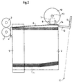
- the feeder shown in FIGS. 1 to 6 contains a sheet support plate 1 which can be moved in height and a sheet stack 2 resting on the sheet support plate 1.
- a printing machine connects to a front of the feeder, of which only transport rollers 3 are shown, which are rotatably mounted parallel to the front edge of the sheet stack 2.
- transport rollers 3 which are rotatably mounted parallel to the front edge of the sheet stack 2.
- Movable front stacking stops 4 and stationary side stacking stops 5 are also arranged at the front of the feeder.
- the sheet support plate 1 is flat in its front and middle area. In the area of the two rear corners of the sheet support plate 1, that is, facing away from the printing press, the top of the sheet support plate 1 is designed such that it extends from the flat area towards the corners increases.
- the sheet support plate 1 thus has an at least partially concave upper side.
- the sheet stack 2 resting on the sheet support plate 1 assumes essentially the same shape, so that the two rear, upper corners of the sheet stack 2 lie higher than its remaining surface.
- a friction wheel 7 is arranged in the area of the two rear corners, which has an axis 8 which extends parallel to the side edges of the sheet 6.
- the friction wheels 7 are resiliently biased towards the top of the uppermost sheet 6 by means not shown, whereby they can deflect resiliently upwards.
- the position of the friction wheels 7 and thus the top edge of the stack can be detected by sensors, not shown, in order to keep the top of the sheet stack 2 at the same height by moving the sheet support plate 1 during operation.
- the friction wheels 7 then press on the rear corners of the uppermost sheet 6 with a defined force.
- the axes 8 of the friction wheels 7 are connected to drive devices (not shown) for rotating the friction wheels 7.
- a feeler foot 9 which has an elongated touch finger 10 which runs approximately parallel to the top of the sheet stack 2.
- the feeler foot 9 is movable in the direction of the sheet stack 2 and away from it by being pivotable about a pivot point 11 in the sheet plane of FIG. 2.
- the feeler 9 can be linearly movable or pivotable about a pivot point that lies in the plane of the top of the sheet stack 2.
- Drive means are provided for moving the feeler foot 9.
- a friction wheel 12 is arranged, which has an axis 13 which is parallel to the The rear edge of the sheet stack 2 extends.
- the friction wheel 12 is located exactly above the touch finger 10 of the touch foot 9 when the touch foot 9 has been pivoted in the direction of the sheet stack 2.
- the friction wheel 12 and its axis 13 can be moved from above in the direction of the sheet stack 2 or the touch finger 10 and away therefrom.
- Drive means are provided for this movement and for a rotation of the friction wheel 12.
- the friction wheels 7 are first rotated in opposite directions, as indicated by arrows in FIG. 1, so that the top sheet 6 is pulled apart and stretched between the friction wheels 7. In this way, an intermediate space 14 is formed between the two uppermost sheets of the sheet stack 2.
- 9 wiper springs or wiping brushes can be provided on the side next to the feeler foot, which press against the rear edge of the sheet stack 2 (not shown in the drawings) ).
- the feeler foot 9 swivels without contact from the rear into the resulting space 14.
- the feeler finger 10 extends over the vertical center line of the friction wheel 12 has penetrated into the intermediate space 14.
- the feeler 9 lowers below the uppermost sheet 6 onto the sheet stack 2 in order to hold the remaining sheets on the sheet stack 2.
- This lowering process can be carried out separately, as indicated by an arrow in FIG. 4, or, if the pivot point 11 is suitably arranged, can result from the pivoting movement of the feeler foot 9.
- the friction wheel 12 lowers, as indicated by a further arrow in FIG. 4, the uppermost sheet 6 being clamped between the friction wheel 12 and the touch finger 10. 5
- the movable stack stops 4 are then pivoted away from the sheet stack 2 and the friction wheel 12 is rotated in the direction of the arrow shown.
- the top of the finger 10 is z. B. a polished metal surface, which has a low coefficient of friction compared to the sheet 6 compared to the friction wheel 12.
- the friction rollers 7 can be lifted off the sheet 6 in the meantime by means not shown. But it is also conceivable that the bias of the friction rollers 7 is so low that the sheet transport is not hindered.
- the length of the touch finger 10 or the distance of the transport rollers 3 from the sheet stack 2 are chosen so that the top sheet 6 is gripped in time by the transport rollers 3 when it exits between the friction wheel 12 and the touch finger 10.
- the friction wheel 12 As soon as the uppermost sheet 6 has emerged between the friction wheel 12 and the touch finger 10 of the touch foot, the friction wheel 12, the touch foot 9 and possibly the friction wheels 7 are brought back into the positions shown in FIG. 2. Thereafter, the next singling cycle can be started immediately while the sheet 6 is still being pulled off the sheet stack 2, whereby it z. B. is in the position shown in dashed lines in Fig. 6. During the removal from the sheet stack 2, the sheet 6 is guided through the side stack stops 5.
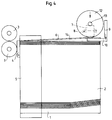
- Tensioning the uppermost sheet and reaching into the resulting space can not only be carried out on the trailing edge of the sheet, but alternatively or additionally on the side edges. Furthermore, it can be carried out on the leading edge of the sheet, as will be described below with reference to FIG. 7.
- a sheet stack 15 is concavely curved in its front region by using a correspondingly curved sheet support plate 16.
- Two friction wheels 17 correspond in structure and function to the friction wheels 7 of the previous embodiment, but are arranged above the front corners of the sheet stack 15.
- One or more grippers 18 are attached to a rotatable gripper bar 19, which is arranged in front of the sheet stack 15.
- the grippers 18 pivot to the front edge 21 of the uppermost sheet 20, grasp the sheet 20 at the front edge 21 and pull it off the sheet stack 15, to feed it to a printing press.
- the remaining sheets are retained by a front stacking stop 22, over which the top sheet 20 is raised when the space 23 between the top two sheets is formed.
- 22 stripping springs or stripping brushes can be provided on the side next to the front stacking stop.
- the embodiment of FIG. 7 does not allow quite as high working speeds as the previous embodiment, since the sheets cannot be pulled overlapping from the sheet stack.
- very few moving parts are required, the masses of which can moreover be kept small, so that the working speeds are more conventional Single sheet feeders can be easily reached or surpassed without excessive acceleration and the associated vibrations.
- the sheet separation is carried out by tensioning the top sheet much more reliably, with significantly less effort and with much less noise than with a conventional single sheet feeder working with air.
Abstract
Description
Der Anleger einer Bogendruckmaschine hat die Aufgabe, die auf einer Bogenauflageplatte exakt vorgestapelten Bogen zu vereinzeln und aufeininderfolgend der Anlage der Druckmaschine zuzuführen. Man findet heute für Bogenoffset-Druckmaschinen hauptsächlich zwei Anlegersysteme, nämlich Einzelbogenanleger mit Saugstange und Schuppenanleger mit Saugkopf.The feeder of a sheet-fed printing press has the task of separating the sheets which have been precisely pre-stacked on a sheet support plate and then feeding them to the printing press in succession. Today there are mainly two feed systems for sheetfed offset printing presses, namely single sheet feeders with a suction rod and scale feeders with a suction head.
Bei einem Einzelbogenanleger wird der oberste Bogen des Stapels pneumatisch durch mehrere an einer Stange befestigte Sauger in der Vorderkante angehoben und dann von Zuführgreifern oder Transportrollen übernommen. Diese führen den Bogen einzeln zur Anlage der Druckmaschine. Durch Einstellung der Saugkraft, durch Veränderung der Kippung der Saugstange und durch Einwirkung von Blasluft gegen die Vorderkante des Stapels kann der Einzelbogenanleger an unterschiedliche Papierdicken und Papierqualitäten angepaßt werden. Sobald der vereinzelte Bogen in die Maschine gelaufen ist, kann ein neuer Bogen vereinzelt werden. Daher muß bei einem Einzelbogenanleger der Vereinzelungsvorgang sehr schnell vonstatten gehen, um die gewünschte Maschinengeschwindigkeit zu erreichen.In the case of a single sheet feeder, the top sheet of the stack is lifted pneumatically by several suction cups attached to a rod in the front edge and then taken over by feed grippers or transport rollers. These guide the sheet individually to the press. By adjusting the suction power, by changing the tilting of the suction rod and by blowing air against the front edge of the stack, the single sheet feeder can be adapted to different paper thicknesses and paper qualities. As soon as the separated sheet has run into the machine, a new sheet can be separated. Therefore, with a single sheet feeder, the separating process must take place very quickly in order to achieve the desired machine speed.
Für höhere Maschinengeschwindigkeiten verwendet man Schuppenanleger, bei denen die Bogen durch einen Saugkopf an der Hinterkante des Stapels vereinzelt werden. Ein Schuppenanleger weist verschiedene pneumatische Trenn- und Schleppsauger auf, die den obersten Bogen abnehmen und ihn dann kontinuierlich dem Anlagetisch zuführen. Zusätzlich sind in der Hinterkante des Anlegeapparates verschiedene Blasvorrichtungen, Abstreifbürsten, Abstreifbleche und Bogenniederhalter angebracht, welche die Aufgabe haben, eine störungsfreie Vereinzelung zu gewährleisten und für einen ruhigen, geraden Transport der Bogen zu sorgen, die auf einem Anlagetisch überlappt werden. Während eines kurzen Stops an der Anlage wird jeder Bogen passergenau ausgerichtet. Sowohl die Blas- und Saugluft als auch die weiteren erwähnten Hilfsmittel müssen vom Drucker genau auf den jeweiligen Bedruckstoff eingestellt werden.For higher machine speeds, scale feeders are used, in which the sheets are separated by a suction head on the rear edge of the stack. A shed feeder has various pneumatic separating and drag suction devices that remove the top sheet and then feed it continuously to the feed table. In addition, there are several in the rear edge of the feeder Blowers, scraper brushes, scraper plates and sheet hold-down are attached, which have the task of ensuring a trouble-free separation and ensure a smooth, straight transport of the sheets that are overlapped on a system table. During a short stop at the system, each sheet is aligned precisely. Both the blowing and suction air as well as the other aids mentioned must be set exactly by the printer to the respective substrate.
Bei den bekannten Anlegersystemen sind somit Saug- bzw. Blasluft erforderlich, und je höher die Arbeitsgeschwindigkeit, um so mehr und um so leistungsfähigere Saug- und Blasvorrichtungen sind erforderlich, bei entsprechend hohem Luftverbrauch. Die Saug- und Blasvorrichtungen verursachen erhebliche Geräusche, und das periodische Ein- und Ausschalten der Luftströmungen und die Bewegung der Saugköpfe im Maschinentakt führen zu schwierig beherrschbaren Schwingungen.In the known feeder systems, suction or blowing air is therefore required, and the higher the working speed, the more and the more powerful suction and blowing devices are required, with a correspondingly high air consumption. The suction and blowing devices cause considerable noise, and the periodic switching on and off of the air flows and the movement of the suction heads in the machine cycle lead to vibrations that are difficult to control.
Der Erfindung liegt die Aufgabe zugrunde, einen Bogenanleger und ein Verfahren zur Bogenvereinzelung zu schaffen, die eine hohe Arbeitsgeschwindigkeit und einen verringerten Aufwand für Saug- und Blasvorrichtungen bzw. einen verringerten Luftverbrauch aufweisen.The invention has for its object to provide a sheet feeder and a method for sheet separation, which have a high working speed and reduced effort for suction and blowing devices and reduced air consumption.
Diese Aufgabe wird gemäß der Erfindung durch eine Vorrichtung mit den Merkmalen des Anspruchs 1 und durch ein Verfahren mit den Merkmalen des Anspruchs 10 gelöst. Vorteilhafte Ausgestaltungen der Erfindung ergeben sich durch die Merkmale der Unteransprüche.This object is achieved according to the invention by a device with the features of
Der auf einer Bogenauflageplatte aufliegende Bogenstapel wird vorgewölbt, vorzugsweise dadurch, daß die Bogenauflageplatte nicht eben ausgebildet wird. Eine konkave Form des Bogenstapels zumindest im oberen Bereich läßt sich alternativ z. B. auch dadurch erreichen, daß an den Seiten eines eben aufliegenden Bogenstapels Mitnehmer angreifen, die ihn teilweise anheben. Es genügt, wenn die Wölbung an der Maschinenseite oder an der maschinenabgewandten Seite des Bogenstapels erzeugt wird. Falls eine konvexe Wölbung gewünscht wird, läßt sich unter Umständen die Wölbung ausnutzen, die ein Bogenstapel häufig von sich aus aufweist.The sheet stack resting on a sheet support plate is bulged, preferably by the sheet support plate not being made flat. A concave shape of the stack of sheets, at least in the upper region, can alternatively be used e.g. B. also achieve that attack on the sides of a sheet stack lying flat drivers, which raise it partially. It is sufficient if the curvature is created on the machine side or on the side of the sheet stack facing away from the machine. If a convex curvature is desired, the curvature which a stack of sheets often has on its own can be used under certain circumstances.
Auf den obersten Bogen drücken mehrere Haftelemente, die vorzugsweise in der Nähe der seitlichen Bogenränder angeordnet sind und die Haftflächen aufweisen, die den Bogen berühren. Im Falle einer konvexen Wölbung werden die Haftelemente bzw. deren Haftflächen anschließend aufeinander zu bewegt. Dadurch hebt sich der oberste Bogen teilweise vom Bogenstapel ab, so daß zwischen dem obersten Bogen und dem Rest des Bogenstapels ein Zwischenraum entsteht.A plurality of adhesive elements press on the uppermost sheet, which are preferably arranged in the vicinity of the lateral sheet edges and have the adhesive surfaces which touch the sheet. In the case of a convex curvature, the adhesive elements or their adhesive surfaces are then moved towards one another. As a result, the uppermost sheet is partially raised from the sheet stack, so that a space is created between the uppermost sheet and the rest of the sheet stack.
Falls ein konkav gewölbter Bogenstapel verwendet wird, werden die Haftflächen voneinander weg bewegt, so daß der oberste Bogen gestreckt wird. Das Strecken des Bogens hat den Vorteil, daß auch dünne Papiere sicher getrennt werden können. Außerdem sind die Abmessungen des entstehenden Zwischenraumes besonders gut definiert. Dies ist von Vorteil, wenn der entstandene Zwischenraum benutzt wird, um den Bogen vollständig von Bogenstapel abzulösen und der Druckmaschine zuzuführen. Nachfolgend werden einige Beispiele dazu beschrieben.If a concave stack of sheets is used, the adhesive surfaces are moved away from each other so that the top sheet is stretched. Stretching the sheet has the advantage that even thin papers can be separated safely. In addition, the dimensions of the resulting space are particularly well defined. This is advantageous if the resulting space is used to completely detach the sheet from the sheet stack and feed it to the printing press. Some examples of this are described below.
Bei einer Ausführungsform, bei der die Wölbung des Bogenstapels im Bereich seiner Vorderseite besteht, d. h. der Seite des Bogenstapels, die der Druckmaschine zugewandt ist, können z. B. Greifer vorgesehen werden, die die Bogenvorderkante erfassen. Die Greifer ziehen den obersten Bogen vom Bogenstapel ab, wobei die übrigen Bogen durch einen Anschlag zurückgehalten werden, und übergeben ihn an die Druckmaschine. Da die Haftelemente den obersten Bogen nur teilweise vom Bogenstapel abgehoben haben, ist seine Lage im Augenblick der Erfassung durch die Greifer genau definiert. Daher kann die übergabe ohne Zwischenstop erfolgen, z. B. an Transportwalzen, die den Bogen in einem Zuge passergenau in die Druckmaschine befördern. Dadurch wird der Bewegungsablauf vergleichmäßigt, und die Maschinengeschwindigkeit kann erhöht werden.In one embodiment, in which the curvature of the sheet stack is in the region of its front side, ie the side of the sheet stack which faces the printing press, z. B. grippers are provided which capture the leading edge of the sheet. The grippers pull the top sheet from the sheet stack, the remaining sheets being held back by a stop, and transfer it to the printing press. Because the adhesive elements only the top sheet partially lifted off the sheet stack, its position is precisely defined at the moment it is gripped. Therefore, the transfer can take place without a stopover, e.g. B. on transport rollers that convey the sheet in register in one go into the printing press. This smoothes the movement and the machine speed can be increased.
Noch höhere Geschwindigkeiten sind mit einer Ausführungsform möglich, bei der der Bogenstapel nicht an der Vorderseite, sondern in seinem hinteren Bereich gewölbt ist. Die Haftelemente heben den obersten Bogen in seinem hinteren Bereich vom Stapel ab, und in den entstehenden Zwischenraum können ein oder mehrere Tastfinger eingeführt werden, welche die übrigen Bogen festhalten. Dies kann an der Hinterseite des Bogenstapels und/oder im hinteren Bereich seiner Seiten durchgeführt werden. Zum Transport des obersten Bogens zur Druckmaschine können z. B. rotierende Reibräder verwendet werden. Noch bevor der Bogen vollständig vom Stapel abgezogen ist, können der oder die Tastfinger gelöst werden, kann der nächste Bogen mit Hilfe der Haftelemente angehoben werden und können der oder die Tastfinger wieder in Position gebracht werden, um den nächsten Bogen zuzuführen. Die Bogen können der Druckmaschine somit eng aufeinanderfolgend oder sogar gestaffelt zugeführt werden. Dennoch bleibt genug Zeit für die bewegten Bauteile, ihre verschiedenen Positionen einzunehmen. Daher kann der Bewegungsablauf so gestaltet werden, daß nur sehr geringe Beschleunigungen der Bauteile auftreten. Dadurch können die bewegten Bauteile und ihre Antriebe schwächer dimensioniert werden, und Schwingungen werden reduziert.Even higher speeds are possible with an embodiment in which the sheet stack is arched not in the front but in its rear area. The adhesive elements lift the uppermost sheet from the stack in its rear area, and one or more touch fingers can be inserted into the resulting space to hold the remaining sheets. This can be done on the back of the sheet stack and / or in the back of its sides. For transporting the top sheet to the printing press, e.g. B. rotating friction wheels can be used. Before the sheet is completely removed from the stack, the finger or fingers can be released, the next sheet can be lifted with the aid of the adhesive elements and the finger or fingers can be brought back into position to feed the next sheet. The sheets can thus be fed to the printing press in close succession or even staggered. Nevertheless, there is enough time for the moving components to take up their various positions. Therefore, the sequence of movements can be designed so that only very slight accelerations of the components occur. As a result, the moving components and their drives can be dimensioned weaker and vibrations are reduced.
Eine besonders vorteilhafte Weiterbildung dieser Ausführungsform besteht darin, daß ein solcher Tastfinger, der die übrigen Bogen festhält, gleichzeitig eine Gegendruckeinrichtung für ein Reibrad bildet. Der oberste Bogen wird zwischen einer reibungsarmen, beispielsweise polierten Oberfläche des Tastfingers und dem Reibrad eingeklemmt, und das Reibrad transportiert den Bogen zuverlässig und praktisch schlupffrei zur Druckmaschine. Da der Reibungskoeffizient zwischen dem Reibrad und dem Bogen wesentlich größer als der Reibungskoeffizient zwischen dem Bogen und dem Tastfinger ist, bleibt das Abzugsverhalten auf lange Zeit konstant.A particularly advantageous development of this embodiment consists in that such a touch finger, which holds the remaining sheets, simultaneously forms a counterpressure device for a friction wheel. The top one The sheet is clamped between a low-friction, for example polished surface of the touch finger and the friction wheel, and the friction wheel conveys the sheet to the printing press reliably and practically without slippage. Since the coefficient of friction between the friction wheel and the sheet is significantly greater than the coefficient of friction between the sheet and the finger, the trigger behavior remains constant for a long time.
Um die Haftflächen aufeinander zu oder voneinander weg zu bewegen, genügt es an sich, wenn eines der Haftelemente entsprechend angetrieben wird. Bei einem spiegelbildlichen Antrieb von einander gegenüberliegenden, gleich aufgebauten Haftelementen ist die Gefahr jedoch geringer, daß der oberste Bogen beim Anheben auf dem Stapel verschoben wird. Alternativ oder zusätzlich können feststehende oder bewegliche Stapelanschläge verwendet werden, um die Bogen exakt ausgerichtet zu halten. Wird der Abzug der Bogen vom Bogenstapel z. B. mittels Reibrädern durchgeführt, die die Bogen an Transportwalzen übergeben, so können die Bogen der Druckmaschine in einem ruhigen, geraden Lauf passergenau zugeführt werden, so daß auf eine Ausrichtung der Bogen vor dem Eintritt in die Druckwerke verzichtet werden kann.In order to move the adhesive surfaces towards or away from each other, it is sufficient in itself if one of the adhesive elements is driven accordingly. In the case of a mirror-image drive of opposing, identically constructed adhesive elements, the risk is lower, however, that the uppermost sheet is shifted when lifting on the stack. Alternatively or additionally, fixed or movable stacking stops can be used to keep the sheets precisely aligned. The deduction of the sheets from the sheet stack z. B. carried out by means of friction wheels that pass the sheet to transport rollers, so the sheet of the printing press can be fed in register in a quiet, straight run, so that an alignment of the sheet before entering the printing units can be dispensed with.
Die Haftelemente, die den jeweils obersten Bogen strecken oder zusammenziehen, können z. B. bewegliche Finger sein, die von der Seite über den Bogenstapel greifen und an ihren Enden Haftflächen tragen. In der bevorzugten Ausführungsform sind die Haftelemente fortlaufend oder intermittierend angetriebene Reibräder, deren Oberflächen die Haftflächen bilden und die federnd gegen die Bogenoberseite drücken. Durch geeignete Einstellung der Anpreßkräfte der Reibräder ist eine Anpassung an unterschiedliche Papiere möglich.The adhesive elements that stretch or contract the top sheet, z. B. be movable fingers that grip from the side over the sheet stack and carry adhesive surfaces at their ends. In the preferred embodiment, the adhesive elements are continuously or intermittently driven friction wheels, the surfaces of which form the adhesive surfaces and which press resiliently against the upper side of the sheet. Appropriate adjustment of the contact pressure of the friction wheels enables adaptation to different papers.
Damit die Reibräder oder sonstigen Haftelemente den Transport der angehobenen Bogen zur Druckmaschine nicht behindern, können sie im Maschinentakt angehoben und wieder auf den Bogen abgesenkt werden. Im Falle einer Verwendung von Reibrädern läßt sich diese Wirkung auch durch Reibräder erzielen, die exzentrisch gelagert und synchron mit dem Maschinentakt angetrieben werden.So that the friction wheels or other adhesive elements do not hinder the transport of the raised sheets to the printing press, they can be raised in the machine cycle and lowered back onto the sheet. If friction wheels are used, this effect can also be achieved by friction wheels which are mounted eccentrically and driven synchronously with the machine cycle.
Während die oben beschriebenen Ausführungsformen völlig ohne Luft auskommen und entsprechend kostengünstig betreibbar und geräuscharm sind, sind auch Ausführungsformen mit einem begrenzten Lufteinsatz denkbar. Beispielsweise kann der oberste Bogen statt durch Reibwalzen auch durch einen Schleppsauger vom Stapel abgezogen werden, wobei die übrigen Bogen zuverlässig auf dem Stapel festgehalten werden. Anstelle von Reibwalzen können auch Saugwalzen verwendet werden, die einen porösen Mantel aufweisen und in denen ein Unterdruck herrscht, so daß der Bogen daran haftet. Der Eingriff in den Zwischenraum zwischen den beiden obersten Bogen kann ebenfalls durch Luft oder luftunterstützt erfolgen, sofern es die Strömungsdynamik zuläßt. Für das anfängliche Trennen der Bogen, für das bei den herkömmlichen Anlegersystemen sehr viel Luft benötigt wird, ist aber in allen diesen Ausführungsformen keine oder nur sehr wenig Luft erforderlich, und die Anzahl der benötigten Saug- bzw. Blasvorrichtungen ist geringer.While the above-described embodiments work entirely without air and are correspondingly inexpensive to operate and low-noise, embodiments with a limited use of air are also conceivable. For example, the uppermost sheet can also be pulled off the stack by a suction device instead of by friction rollers, the remaining sheets being reliably held on the stack. Instead of friction rollers, suction rollers can also be used, which have a porous jacket and in which a negative pressure prevails, so that the sheet adheres to it. The intervention in the space between the two uppermost arches can also be carried out by air or air-assisted, provided the flow dynamics allow it. For the initial separation of the sheets, for which a lot of air is required in the conventional feeder systems, no or very little air is required in all of these embodiments, and the number of suction or blowing devices required is smaller.
Weitere Merkmale und Vorteile der Erfindung ergeben sich aus der folgenden Beschreibung mehrerer Ausführungsformen und aus der Zeichnung, auf die Bezug genommen wird.Further features and advantages of the invention will become apparent from the following description of several embodiments and from the drawing, to which reference is made.
Darin zeigen:
- Fig. 1
- einen Anleger für eine Bogendruckmaschine von hinten;
- Fig. 2
bis 5 - den Anleger von Fig. 1 im Längsschnitt von der linken Seite aus gesehen in verschiedenen Phasen eines Vereinzelungszyklus;
- Fig. 6
- eine Ansicht von oben auf den Anleger von Fig. 1
bis 5;
und - Fig. 7
- eine weitere Ausführungsform eines Anlegers für eine Bogendruckmaschine im Längsschnitt.
- Fig. 1
- a feeder for a sheet-fed printing machine from behind;
- 2 to 5
- the feeder of Figure 1 seen in longitudinal section from the left side in different phases of a separation cycle.
- Fig. 6
- a top view of the feeder of Fig. 1 to 5;
and - Fig. 7
- a further embodiment of a feeder for a sheet-fed printing machine in longitudinal section.
Der in Fig. 1 bis 6 gezeigte Anleger enthält eine in der Höhe verfahrbare Bogenauflageplatte 1 und einen auf der Bogenauflageplatte 1 aufliegenden Bogenstapel 2.The feeder shown in FIGS. 1 to 6 contains a
An eine Vorderseite des Anlegers schließt sich eine Druckmaschine an, von der lediglich Transportwalzen 3 eingezeichnet sind, die parallel zur Vorderkante des Bogenstapels 2 drehbar gelagert sind. Jeweils zwei Transportwalzen 3, die längs einer Linie an ihrem Umfang aneinander angrenzen, bilden ein Walzenpaar zur übergabe von Bogen an die Druckmaschine. Vorne am Anleger sind außerdem bewegliche vordere Stapelanschläge 4 sowie feststehende seitliche Stapelanschläge 5 (Fig. 2 bis 6) angeordnet.A printing machine connects to a front of the feeder, of which only
Die Bogenauflageplatte 1 ist in ihrem vorderen und mittleren Bereich eben. Im Bereich der beiden hinteren, d. h. von der Druckmaschine abgewandten Ecken der Bogenauflageplatte 1 ist die Oberseite der Bogenauflageplatte 1 so ausgebildet, daß sie von dem ebenen Bereich aus in Richtung auf die Ecken ansteigt. Die Bogenauflageplatte 1 weist also eine zumindest teilweise konkave Oberseite auf. Der auf der Bogenauflageplatte 1 aufliegende Bogenstapel 2 nimmt im wesentlichen die gleiche Form an, so daß die beiden hinteren, oberen Ecken des Bogenstapels 2 höher als seine übrige Oberfläche liegen.The
Oberhalb des obersten Bogens 6 des Bogenstapels 2 ist im Bereich der beiden hinteren Ecken jeweils ein Reibrad 7 angeordnet, das eine Achse 8 aufweist, die sich parallel zu den Seitenkanten des Bogens 6 erstreckt. Die Reibräder 7 sind durch nicht gezeigte Mittel federnd in Richtung auf die Oberseite des obersten Bogens 6 vorgespannt, wobei sie federnd nach oben ausweichen können. Die Lage der Reibräder 7 und somit der Stapeloberkante kann durch nicht gezeigte Sensoren erfaßt werden, um die Oberseite des Bogenstapels 2 durch Verfahren der Bogenauflageplatte 1 im Betrieb auf gleicher Höhe zu halten. Die Reibräder 7 drücken dann mit einer definierten Kraft auf die hinteren Ecken des jeweils obersten Bogens 6. Die Achsen 8 der Reibräder 7 sind mit nicht gezeigten Antriebseinrichtungen zum Drehen der Reibräder 7 verbunden.Above the
An der Hinterkante des Bogenstapels 2 ist ein Tastfuß 9 angeordnet, der einen langgestreckten Tastfinger 10 aufweist, der ungefähr parallel zur Oberseite des Bogenstapels 2 verläuft. Der Tastfuß 9 ist in Richtung auf den Bogenstapel 2 und davon weg beweglich, indem er in der Blattebene von Fig. 2 um einen Drehpunkt 11 schwenkbar ist. Alternativ kann der Tastfuß 9 linear beweglich oder um einen Drehpunkt schwenkbar sein, der in der Ebene der Oberseite des Bogenstapels 2 liegt. Zum Bewegen des Tastfußes 9 sind nicht gezeigte Antriebsmittel vorgesehen.At the rear edge of the
Zwischen den beiden Reibrädern 7 ist ein Reibrad 12 angeordnet, das eine Achse 13 aufweist, die sich parallel zur Hinterkante des Bogenstapels 2 erstreckt. Das Reibrad 12 befindet sich genau oberhalb des Tastfingers 10 des Tastfußes 9, wenn der Tastfuß 9 in Richtung auf den Bogenstapel 2 geschwenkt worden ist. Das Reibrad 12 und seine Achse 13 sind von oben in Richtung auf den Bogenstapel 2 bzw. den Tastfinger 10 und davon weg verfahrbar. Für diese Bewegung und für eine Drehung des Reibrades 12 sind nicht gezeigte Antriebsmittel vorgesehen.Between the two
Im Betrieb des Anlegers werden zuerst die Reibräder 7 in einander entgegengesetzten Richtungen gedreht, wie in Fig. 1 durch Pfeile angezeigt, so daß der oberste Bogen 6 auseinandergezogen und zwischen den Reibrädern 7 gespannt wird. Auf diese Weise wird zwischen den beiden obersten Bogen des Bogenstapels 2 ein Zwischenraum 14 gebildet. Um auch bei kritischen Papieren, etwa sehr dünnen Bogen, eine sichere Abtrennung nur eines einzigen Bogens vom Bogenstapel 2 zu gewährleisten, können seitlich neben dem Tastfuß 9 Abstreiffedern oder Abstreifbürsten vorgesehen werden, die gegen die Hinterkante des Bogenstapels 2 drücken (in den Zeichnungen nicht dargestellt).During operation of the feeder, the
In diesem Zustand, in Fig. 2 von der Seite dargestellt, schwenkt der Tastfuß 9 berührungsfrei von hinten in den entstandenen Zwischenraum 14. Durch diese Schwenkbewegung erreicht er die in Fig. 3 gezeigte Position, in der der Tastfinger 10 über die vertikale Mittellinie des Reibrades 12 hinaus in den Zwischenraum 14 eingedrungen ist. Anschließend senkt sich der Tastfuß 9 unterhalb des obersten Bogens 6 auf den Bogenstapel 2 ab, um die übrigen Bogen auf dem Bogenstapel 2 festzuhalten. Dieser Absenkvorgang kann separat durchgeführt werden, wie in Fig. 4 durch einen Pfeil angezeigt, oder sich bei geeigneter Anordnung des Drehpunktes 11 durch die Schwenkbewegung des Tastfußes 9 ergeben.In this state, shown from the side in FIG. 2, the
Gleichzeitig mit dem Absenken des Tastfußes 9 auf den Bogenstapel 2 oder im Anschluß daran senkt sich das Reibrad 12 ab, wie in Fig. 4 durch einen weiteren Pfeil angezeigt, wobei der oberste Bogen 6 zwischen dem Reibrad 12 und dem Tastfinger 10 eingeklemmt wird. Wie in Fig. 5 gezeigt, werden danach die beweglichen Stapelanschläge 4 vom Bogenstapel 2 weggeschwenkt und wird das Reibrad 12 in der eingezeichneten Pfeilrichtung gedreht.Simultaneously with the lowering of the
Die Oberseite des Tastfingers 10 ist z. B. eine polierte Metalloberfläche, die verglichen mit dem Reibrad 12 einen geringen Reibungskoeffizienten gegenüber dem Bogen 6 aufweist. Dadurch wird der oberste Bogen 6 nach vorne in Richtung auf die Transportwalzen 3 geschoben. Um dies zu erleichtern, können die Reibwalzen 7 durch nicht gezeigte Mittel zwischenzeitlich von dem Bogen 6 abgehoben werden. Es ist aber auch denkbar, daß die Vorspannung der Reibwalzen 7 so gering ist, daß der Bogentransport nicht behindert wird.The top of the
Die Länge des Tastfingers 10 bzw. die Entfernung der Transportwalzen 3 vom Bogenstapel 2 werden so gewählt, daß der oberste Bogen 6 rechtzeitig von den Transportwalzen 3 ergriffen wird, wenn er zwischen dem Reibrad 12 und dem Tastfinger 10 austritt.The length of the
Sobald der oberste Bogen 6 zwischen dem Reibrad 12 und dem Tastfinger 10 des Tastfußes ausgetreten ist, werden das Reibrad 12, der Tastfuß 9 und ggf. die Reibräder 7 wieder in die in Fig. 2 gezeigten Positionen gebracht. Danach kann sofort mit dem nächsten Vereinzelungszyklus begonnen werden, während der Bogen 6 noch vom Bogenstapel 2 abgezogen wird, wobei er sich z. B. in der Position befindet, die in Fig. 6 gestrichelt dargestellt ist. Während des Abziehens vom Bogenstapel 2 wird der Bogen 6 durch die seitlichen Stapelanschläge 5 geführt.As soon as the
Das Spannen des obersten Bogens und das Eingreifen in den entstehenden Zwischenraum kann nicht nur an der Bogenhinterkante durchgeführt werden, sondern alternativ oder zusätzlich an den Seitenkanten. Ferner kann es an der Bogenvorderkante durchgeführt werden, wie nachfolgend unter Bezugnahme auf Fig. 7 beschrieben wird.Tensioning the uppermost sheet and reaching into the resulting space can not only be carried out on the trailing edge of the sheet, but alternatively or additionally on the side edges. Furthermore, it can be carried out on the leading edge of the sheet, as will be described below with reference to FIG. 7.
In der Ausführungsform von Fig. 7 ist ein Bogenstapel 15 in seinem vorderen Bereich konkav gewölbt, indem eine entsprechend gewölbte Bogenauflageplatte 16 verwendet wird. Zwei Reibräder 17 entsprechen in Aufbau und Funktion den Reibrädern 7 der vorhergehenden Ausführungsform, sind jedoch über den vorderen Ecken des Bogenstapels 15 angeordnet. Ein oder mehrere Greifer 18 sind an einer drehbaren Greiferstange 19 angebracht, die vor dem Bogenstapel 15 angeordnet ist.In the embodiment of FIG. 7, a
Nachdem die Reibräder 17 den obersten Bogen 20 des Bogenstapels 15 nach dem in Fig. 1 dargestellten Prinzip gespannt haben, schwenken die Greifer 18 zur Vorderkante 21 des obersten Bogens 20, ergreifen den Bogen 20 an der Vorderkante 21 und ziehen ihn vom Bogenstapel 15 ab, um ihn einer Druckmaschine zuzuführen. Die übrigen Bogen werden durch einen vorderen Stapelanschlag 22 zurückgehalten, über den hinweg jeweils der oberste Bogen 20 angehoben wird, wenn der Zwischenraum 23 zwischen den beiden obersten Bogen gebildet wird. Außerdem können seitlich neben dem vorderen Stapelanschlag 22 Abstreiffedern oder Abstreifbürsten vorgesehen sein.After the
Die Ausführungsform von Fig. 7 erlaubt nicht ganz so hohe Arbeitsgeschwindigkeiten wie die vorhergehende Ausführungsform, da die Bogen nicht überlappend vom Bogenstapel abgezogen werden können. Andererseits sind bei der Ausführungsform von Fig. 7 nur sehr wenige bewegte Teile erforderlich, deren Massen sich überdies gering halten lassen, so daß die Arbeitsgeschwindigkeiten herkömmlicher Einzelbogenanleger leicht erreicht oder übertroffen werden können, ohne daß übermäßige Beschleunigungen und die damit einhergehenden Schwingungen auftreten. Außerdem erfolgt die Bogentrennung durch das Spannen des obersten Bogens wesentlich zuverlässiger, mit wesentlich weniger Aufwand und mit wesentlich weniger Geräusch als bei einem herkömmlichen, mit Luft arbeitenden Einzelbogenanleger.The embodiment of FIG. 7 does not allow quite as high working speeds as the previous embodiment, since the sheets cannot be pulled overlapping from the sheet stack. On the other hand, in the embodiment of FIG. 7, very few moving parts are required, the masses of which can moreover be kept small, so that the working speeds are more conventional Single sheet feeders can be easily reached or surpassed without excessive acceleration and the associated vibrations. In addition, the sheet separation is carried out by tensioning the top sheet much more reliably, with significantly less effort and with much less noise than with a conventional single sheet feeder working with air.
- 11
- BogenauflageplatteSheet support plate
- 22nd
- BogenstapelSheet stack
- 33rd
- TransportwalzeTransport roller
- 44th
- StapelanschlagStack stop
- 55
- StapelanschlagStack stop
- 66
- oberster Bogentop bow
- 77
- ReibradFriction wheel
- 88th
- Achseaxis
- 99
- TastfußFeet
- 1010th
- TastfingerTouch finger
- 1111
- Drehpunktpivot point
- 1212th
- ReibradFriction wheel
- 1313
- Achseaxis
- 1414
- ZwischenraumSpace
- 1515
- BogenstapelSheet stack
- 1616
- BogenauflageplatteSheet support plate
- 1717th
- ReibradFriction wheel
- 1818th
- GreiferGripper
- 1919th
- GreiferstangeGripper bar
- 2020th
- oberster Bogentop bow
- 2121
- Vorderkante des obersten BogensFront edge of the top sheet
- 2222
- StapelanschlagStack stop
Claims (12)
gekennzeichnet durch
eine Einrichtung (1; 16) zum wenigstens teilweisen Wölben eines Bogenstapels (2; 15) wenigstens in seinem oberen Bereich und durch wenigstens zwei Haftelemente (7; 17), die im Abstand zueinander auf der Oberseite des Bogenstapels angeordnet sind und die Haftflächen aufweisen, die wenigstens teilweise und/oder zeitweise auf die Oberseite des Bogenstapels drücken, wobei wenigstens eines der Haftelemente antreibbar ist, um Haftflächen, die gerade auf die Oberseite des Bogenstapels drücken, aufeinander zu oder voneinander weg zu bewegen, so daß zwischen den beiden obersten Bogen des Bogenstapels ein Zwischenraum (14; 23) entsteht.Feeder for a sheet printing machine,
marked by
a device (1; 16) for at least partially arching a sheet stack (2; 15) at least in its upper region and by means of at least two adhesive elements (7; 17) which are arranged at a distance from one another on the upper side of the sheet stack and have the adhesive surfaces, which at least partially and / or temporarily press on the top of the sheet stack, at least one of the adhesive elements being drivable in order to move adhesive surfaces which are just pressing on the top of the sheet stack toward or away from one another, so that between the two uppermost sheets of the A gap (14; 23) is formed in the stack of sheets.
gekennzeichnet durch
eine Einrichtung (10; 18), die in den Zwischenraum (14; 23) zwischen den beiden obersten Bogen eingreift.Investor according to claim 1,
marked by
a device (10; 18) which engages in the space (14; 23) between the two uppermost arches.
dadurch gekennzeichnet,
daß die Einrichtung, die in den Zwischenraum eingreift, einen oder mehrere bewegliche Greifer (18) umfaßt, die den obersten Bogen (20) ergreifen und vom Bogenstapel (15) abziehen.Investor according to claim 2,
characterized by
that the device which engages in the intermediate space comprises one or more movable grippers (18) which grip the uppermost sheet (20) and pull it off the sheet stack (15).
dadurch gekennzeichnet,
daß die Einrichtung, die in den Zwischenraum eingreift, einen oder mehrere berührungsfrei in den Zwischenraum hinein bewegliche Tastfinger (10) enthält, die auf den Bogen unterhalb des obersten Bogens (6) absenkbar sind.Investor according to claim 2,
characterized by
that the device which engages in the intermediate space contains one or more touch fingers (10) which can move into the intermediate space without contact and which can be lowered onto the sheet below the uppermost sheet (6).
dadurch gekennzeichnet,
daß wenigstens einer der Tastfinger (10) eine reibungsarme Oberfläche aufweist, die eine Gegendruckeinrichtung für ein oberhalb des Tastfingers angeordnetes Reibrad (12) bildet, das auf den obersten Bogen (6) absenkbar ist, um den obersten Bogen in Richtung auf eine Anlage (3) der Druckmaschine zu befördern.Investor according to claim 4,
characterized by
that at least one of the touch fingers (10) has a low-friction surface, which forms a counterpressure device for a friction wheel (12) arranged above the touch finger, which can be lowered onto the uppermost sheet (6) in order to move the uppermost sheet in the direction of a system (3 ) of the printing press.
dadurch gekennzeichnet,
daß die Anlage einer dazugehörigen Druckmaschine ein oder mehrere nahe am Bogenstapel (2) angeordnete Paare von Transportwalzen (3) umfaßt.Investor according to claim 5,
characterized by
that the system of an associated printing press comprises one or more pairs of transport rollers (3) arranged close to the sheet stack (2).
dadurch gekennzeichnet,
daß die Haftelemente Reibräder (7; 17) sind, die in Richtung auf die Oberseite des Bogenstapels (2; 15) vorgespannt sind.Investor according to one of the preceding claims,
characterized by
that the adhesive elements are friction wheels (7; 17) which are biased towards the top of the sheet stack (2; 15).
dadurch gekennzeichnet,
daß auf jeder Seite des Bogenstapels (2; 15) in der Nähe der Bogenvorderkanten bzw. der Bogenhinterkanten jeweils ein Reibrad (7; 17) angeordnet ist, das antreibbar auf einer Achse (8) gelagert ist, die quer zu den Bogenvorderkanten bzw. Bogenhinterkanten verläuft.Investor according to claim 7,
characterized by
that a friction wheel (7; 17) is arranged on each side of the sheet stack (2; 15) in the vicinity of the sheet leading edges or the sheet trailing edges, which is drivably mounted on an axis (8) which is transverse to the sheet leading edges or sheet trailing edges runs.
dadurch gekennzeichnet,
daß die Einrichtung zum Wölben des Bogenstapels (2; 15) eine wenigstens teilweise konvexe oder konkave Bogenauflageplatte (1; 16) ist.Investor according to one of the preceding claims,
characterized by
that the device for arching the sheet stack (2; 15) is an at least partially convex or concave sheet support plate (1; 16).
dadurch gekennzeichnet,
daß der Bogenstapel (2; 15) wenigstens teilweise und wenigstens in seinem oberen Bereich gewölbt wird und daß in dem gewölbten Bereich des Bogenstapels der oberste Bogen (6; 20) durch mechanisches Angreifen an der Bogenoberseite gespannt oder zusammengeschoben wird, so daß zwischen den beiden obersten Bogen des gewölbten Bogenstapels ein Zwischenraum (14; 23) entsteht.Method for separating sheets that are stacked on top of one another in a feeder of a sheet-fed printing press,
characterized by
that the sheet stack (2; 15) is arched at least partially and at least in its upper area and that in the arched area of the sheet stack the uppermost sheet (6; 20) is tensioned or pushed together by mechanical engagement on the upper side of the sheet, so that between the two a gap (14; 23) is created in the uppermost sheet of the arched sheet stack.
dadurch gekennzeichnet,
daß der Bogenstapel (2; 15) konkav gewölbt wird, daß auf jeder Seite des Bogenstapels wenigstens ein Haftelement (7; 17) gegen die Oberseite des obersten Bogens (6; 20) gedrückt wird und daß die Oberflächen der Haftelemente, die gegen den obersten Bogen drücken, seitlich voneinander weg bewegt werden, um den obersten Bogen zu spannen.A method according to claim 10,
characterized by
that the sheet stack (2; 15) is concavely curved, that on each side of the sheet stack at least one adhesive element (7; 17) is pressed against the top of the uppermost sheet (6; 20) and that the surfaces of the adhesive elements against the uppermost Press the bow, move it sideways to tension the top bow.
dadurch gekennzeichnet,
daß der Zwischenraum (14) auf einer Seite des Bogenstapels erzeugt wird, die von einer Anlage (3) der Bogendruckmaschine entfernt ist, daß in den Zwischenraum zwischen den beiden obersten Bogen eingegriffen wird, um den Bogen unterhalb des obersten Bogens (6) festzuhalten, daß der oberste Bogen mit mechanischen Mitteln (12) in Richtung auf die Druckmaschine befördert und an diese übergeben wird und daß dieser Vorgang von neuem begonnen wird, noch während der zuletzt vereinzelte Bogen vom Bogenstapel (2) abgezogen wird.A method according to claim 10 or claim 11,
characterized by
that the intermediate space (14) is created on a side of the sheet stack which is remote from a system (3) of the sheet-fed printing machine, that the intermediate space between the two uppermost sheets is gripped in order to hold the sheet underneath the uppermost sheet (6), that the top sheet by mechanical means (12) in Directed to the printing press and transferred to this and that this process is started again while the last separated sheet is withdrawn from the sheet stack (2).
Applications Claiming Priority (2)
| Application Number | Priority Date | Filing Date | Title |
|---|---|---|---|
| DE19543382 | 1995-11-21 | ||
| DE19543382A DE19543382C2 (en) | 1995-11-21 | 1995-11-21 | Process for separating sheets and feeders for a sheet-fed printing machine to carry out the process |
Publications (3)
| Publication Number | Publication Date |
|---|---|
| EP0775656A2 true EP0775656A2 (en) | 1997-05-28 |
| EP0775656A3 EP0775656A3 (en) | 1998-09-09 |
| EP0775656B1 EP0775656B1 (en) | 2002-08-07 |
Family
ID=7778025
Family Applications (1)
| Application Number | Title | Priority Date | Filing Date |
|---|---|---|---|
| EP96118618A Expired - Lifetime EP0775656B1 (en) | 1995-11-21 | 1996-11-20 | Sheet feeder and method of separating sheets |
Country Status (5)
| Country | Link |
|---|---|
| US (1) | US5915682A (en) |
| EP (1) | EP0775656B1 (en) |
| JP (1) | JPH09169442A (en) |
| AU (1) | AU7186196A (en) |
| DE (2) | DE19543382C2 (en) |
Families Citing this family (9)
| Publication number | Priority date | Publication date | Assignee | Title |
|---|---|---|---|---|
| DE10147410B4 (en) * | 2001-09-26 | 2005-08-18 | Helmut Steinhilber | Method and device for separating leaves from a stack |
| DE102004017348B3 (en) * | 2004-04-06 | 2005-04-21 | Helmut Steinhilber | Singling device for removing sheets of paper from stack uses rollers moving over top sheet in stack to slip sheet off stack in opposite direction to separation direction |
| JP2007204162A (en) * | 2006-01-30 | 2007-08-16 | Fujifilm Corp | Automatic feeder for lithographic printing plate |
| WO2007086580A1 (en) * | 2006-01-30 | 2007-08-02 | Fujifilm Corporation | Automatic feeding device for lithographic printing plates |
| JP2007246205A (en) * | 2006-03-15 | 2007-09-27 | Fujifilm Corp | Automatic feeding device for lithographic printing plate |
| JP2007204164A (en) * | 2006-01-30 | 2007-08-16 | Fujifilm Corp | Automatic feeder of lithographic printing plate |
| US9682415B2 (en) * | 2014-03-26 | 2017-06-20 | Novelis Inc. | De-stacking process for the separation of lubricated aluminum sheets |
| US10421629B2 (en) | 2017-03-02 | 2019-09-24 | Kabushiki Kaisha Toshiba | Paper feed apparatus and image forming apparatus |
| DE102022122393A1 (en) | 2021-09-07 | 2023-03-09 | Mabeg Systems Gmbh | Variable sheet feed |
Family Cites Families (8)
| Publication number | Priority date | Publication date | Assignee | Title |
|---|---|---|---|---|
| US2827288A (en) * | 1954-11-23 | 1958-03-18 | Old Town Corp | Sheet feeding device |
| US3627307A (en) * | 1970-02-26 | 1971-12-14 | Optische Ind De Oude Delft Nv | Film-changing device |
| US4165870A (en) * | 1978-03-20 | 1979-08-28 | International Business Machines Corporation | Wave generator to shingle sheets |
| JPS58139932A (en) * | 1982-02-10 | 1983-08-19 | Sharp Corp | Vacuum separation type document sheet suction device |
| DE3211371C2 (en) * | 1982-03-27 | 1984-02-09 | Fraunhofer-Gesellschaft zur Förderung der angewandten Forschung e.V., 8000 München | Device for separating the topmost sheet of a stack of sheet-like material |
| SU1315090A1 (en) * | 1985-07-29 | 1987-06-07 | Ростовский научно-исследовательский институт технологии машиностроения | Method of separating upper sheet from a stack |
| JPS63247237A (en) * | 1987-03-31 | 1988-10-13 | Kao Corp | Separation device for paper sheet |
| SU1680606A1 (en) * | 1989-02-03 | 1991-09-30 | Московский Полиграфический Институт | Method of successive feed of flexible sheet stock from pile |
-
1995
- 1995-11-21 DE DE19543382A patent/DE19543382C2/en not_active Expired - Fee Related
-
1996
- 1996-11-20 AU AU71861/96A patent/AU7186196A/en not_active Abandoned
- 1996-11-20 EP EP96118618A patent/EP0775656B1/en not_active Expired - Lifetime
- 1996-11-20 DE DE59609537T patent/DE59609537D1/en not_active Expired - Lifetime
- 1996-11-21 JP JP8310898A patent/JPH09169442A/en active Pending
- 1996-11-21 US US08/759,826 patent/US5915682A/en not_active Expired - Lifetime
Non-Patent Citations (1)
| Title |
|---|
| None |
Also Published As
| Publication number | Publication date |
|---|---|
| JPH09169442A (en) | 1997-06-30 |
| EP0775656A3 (en) | 1998-09-09 |
| US5915682A (en) | 1999-06-29 |
| DE19543382C2 (en) | 1999-05-27 |
| DE59609537D1 (en) | 2002-09-12 |
| EP0775656B1 (en) | 2002-08-07 |
| AU7186196A (en) | 1997-05-29 |
| DE19543382A1 (en) | 1997-05-28 |
Similar Documents
| Publication | Publication Date | Title |
|---|---|---|
| DE3418344C2 (en) | ||
| DE3531889C2 (en) | Separating device for the uppermost sheet of a sheet stack with an air knife acting on the front side of the sheet stack with blown air | |
| DE2638767C2 (en) | Sheet separating device | |
| DE202006013884U1 (en) | Apparatus for producing and controlling samples of supporting sheets by means of a vacuum conveyor | |
| DE2649959A1 (en) | Transfer device for part-stack of printed sheets - has grab reciprocating above inclined guide delivering to table | |
| EP1770036B1 (en) | Sheet guiding device for sheet feeder | |
| DE19543382C2 (en) | Process for separating sheets and feeders for a sheet-fed printing machine to carry out the process | |
| EP0417503A1 (en) | Method and means for handling piled, preferably folded printed products | |
| DE2244249C2 (en) | Sheet feeding device | |
| EP0773179B1 (en) | Device for making auxiliary stacks during continuous pile exchange in a piler of a printing machine | |
| CH652344A5 (en) | TENSIONER OF A BOWING DEVICE. | |
| DE2628809A1 (en) | DEVICE AND METHOD FOR INDIVIDUAL FEEDING OF STACKED OBJECTS | |
| DE19649341A1 (en) | Method and non-stop delivery device for a sheet-fed printing machine | |
| EP0806391B1 (en) | Device for feeding printed articles to a further work station | |
| DE19614491A1 (en) | Sheet brake in the delivery of a printing press | |
| DE4323905A1 (en) | Device for separating flat objects | |
| DE4214232C1 (en) | Suction pick-up for sheet rear edge - has transport suction grips interlaced with lift suction grips to prevent rear edge of paper dropping | |
| DE3531145C2 (en) | ||
| DE102020116074B4 (en) | Device and method for depositing and positioning a stack forming aid | |
| DE3210942A1 (en) | Device for laterally aligning the top sheet of a pile of sheets | |
| DE2753048C2 (en) | Method and apparatus for producing a bundled bar from printed sheets | |
| DE19645239B4 (en) | Sheetfed, especially for printing presses | |
| DE4447204C2 (en) | Suction head | |
| DE10258038A1 (en) | Method and device for separating the sheets of a record carrier from a stack | |
| DE10159933A1 (en) | Paper unloading device for a cylinder screen printing machine |
Legal Events
| Date | Code | Title | Description |
|---|---|---|---|
| PUAI | Public reference made under article 153(3) epc to a published international application that has entered the european phase |
Free format text: ORIGINAL CODE: 0009012 |
|
| 17P | Request for examination filed |
Effective date: 19961121 |
|
| AK | Designated contracting states |
Kind code of ref document: A2 Designated state(s): CH DE ES FR GB LI NL |
|
| PUAL | Search report despatched |
Free format text: ORIGINAL CODE: 0009013 |
|
| AK | Designated contracting states |
Kind code of ref document: A3 Designated state(s): CH DE ES FR GB LI NL |
|
| 17Q | First examination report despatched |
Effective date: 20000728 |
|
| GRAG | Despatch of communication of intention to grant |
Free format text: ORIGINAL CODE: EPIDOS AGRA |
|
| GRAG | Despatch of communication of intention to grant |
Free format text: ORIGINAL CODE: EPIDOS AGRA |
|
| GRAH | Despatch of communication of intention to grant a patent |
Free format text: ORIGINAL CODE: EPIDOS IGRA |
|
| GRAH | Despatch of communication of intention to grant a patent |
Free format text: ORIGINAL CODE: EPIDOS IGRA |
|
| GRAA | (expected) grant |
Free format text: ORIGINAL CODE: 0009210 |
|
| AK | Designated contracting states |
Kind code of ref document: B1 Designated state(s): CH DE ES FR GB LI NL |
|
| PG25 | Lapsed in a contracting state [announced via postgrant information from national office to epo] |
Ref country code: NL Free format text: LAPSE BECAUSE OF FAILURE TO SUBMIT A TRANSLATION OF THE DESCRIPTION OR TO PAY THE FEE WITHIN THE PRESCRIBED TIME-LIMIT Effective date: 20020807 |
|
| REG | Reference to a national code |
Ref country code: GB Ref legal event code: FG4D Free format text: NOT ENGLISH |
|
| REG | Reference to a national code |
Ref country code: CH Ref legal event code: EP |
|
| REF | Corresponds to: |
Ref document number: 59609537 Country of ref document: DE Date of ref document: 20020912 |
|
| GBT | Gb: translation of ep patent filed (gb section 77(6)(a)/1977) |
Effective date: 20020902 |
|
| NLV1 | Nl: lapsed or annulled due to failure to fulfill the requirements of art. 29p and 29m of the patents act | ||
| PG25 | Lapsed in a contracting state [announced via postgrant information from national office to epo] |
Ref country code: FR Free format text: LAPSE BECAUSE OF FAILURE TO SUBMIT A TRANSLATION OF THE DESCRIPTION OR TO PAY THE FEE WITHIN THE PRESCRIBED TIME-LIMIT Effective date: 20030221 |
|
| ET | Fr: translation filed | ||
| PG25 | Lapsed in a contracting state [announced via postgrant information from national office to epo] |
Ref country code: ES Free format text: LAPSE BECAUSE OF FAILURE TO SUBMIT A TRANSLATION OF THE DESCRIPTION OR TO PAY THE FEE WITHIN THE PRESCRIBED TIME-LIMIT Effective date: 20030228 |
|
| PLBE | No opposition filed within time limit |
Free format text: ORIGINAL CODE: 0009261 |
|
| STAA | Information on the status of an ep patent application or granted ep patent |
Free format text: STATUS: NO OPPOSITION FILED WITHIN TIME LIMIT |
|
| 26N | No opposition filed |
Effective date: 20030508 |
|
| PGFP | Annual fee paid to national office [announced via postgrant information from national office to epo] |
Ref country code: GB Payment date: 20141121 Year of fee payment: 19 Ref country code: CH Payment date: 20141125 Year of fee payment: 19 Ref country code: DE Payment date: 20141126 Year of fee payment: 19 |
|
| PGFP | Annual fee paid to national office [announced via postgrant information from national office to epo] |
Ref country code: FR Payment date: 20141120 Year of fee payment: 19 |
|
| REG | Reference to a national code |
Ref country code: DE Ref legal event code: R119 Ref document number: 59609537 Country of ref document: DE |
|
| REG | Reference to a national code |
Ref country code: CH Ref legal event code: PL |
|
| GBPC | Gb: european patent ceased through non-payment of renewal fee |
Effective date: 20151120 |
|
| PG25 | Lapsed in a contracting state [announced via postgrant information from national office to epo] |
Ref country code: LI Free format text: LAPSE BECAUSE OF NON-PAYMENT OF DUE FEES Effective date: 20151130 Ref country code: CH Free format text: LAPSE BECAUSE OF NON-PAYMENT OF DUE FEES Effective date: 20151130 |
|
| REG | Reference to a national code |
Ref country code: FR Ref legal event code: ST Effective date: 20160729 |
|
| PG25 | Lapsed in a contracting state [announced via postgrant information from national office to epo] |
Ref country code: GB Free format text: LAPSE BECAUSE OF NON-PAYMENT OF DUE FEES Effective date: 20151120 Ref country code: DE Free format text: LAPSE BECAUSE OF NON-PAYMENT OF DUE FEES Effective date: 20160601 |
|
| PG25 | Lapsed in a contracting state [announced via postgrant information from national office to epo] |
Ref country code: FR Free format text: LAPSE BECAUSE OF FAILURE TO SUBMIT A TRANSLATION OF THE DESCRIPTION OR TO PAY THE FEE WITHIN THE PRESCRIBED TIME-LIMIT Effective date: 20151130 |