JP2007246205A - Automatic feeding device for lithographic printing plate - Google Patents
Automatic feeding device for lithographic printing plate Download PDFInfo
- Publication number
- JP2007246205A JP2007246205A JP2006070332A JP2006070332A JP2007246205A JP 2007246205 A JP2007246205 A JP 2007246205A JP 2006070332 A JP2006070332 A JP 2006070332A JP 2006070332 A JP2006070332 A JP 2006070332A JP 2007246205 A JP2007246205 A JP 2007246205A
- Authority
- JP
- Japan
- Prior art keywords
- printing plate
- lithographic printing
- uppermost
- roller
- plate
- Prior art date
- Legal status (The legal status is an assumption and is not a legal conclusion. Google has not performed a legal analysis and makes no representation as to the accuracy of the status listed.)
- Pending
Links
Images


Abstract
Description
この発明は、複数の平版刷版だけを横方向にして重ねて束にした状態で装填し、吸盤を用いて各平版刷版を1枚づつ持ち上げることにより枚葉分離して搬出する平版刷版の自動供給装置に関する。 The present invention relates to a lithographic printing plate in which only a plurality of lithographic printing plates are loaded in a stacked state in a horizontal direction and are separated into a sheet by lifting each lithographic printing plate one by one using a suction cup. Relates to the automatic feeding apparatus.
一般に、オフセット印刷には、平版刷版(いわゆるPS版)が利用されている。また、この平版印刷の分野では、未露光の平版刷版の供給を受けて、この平版刷版に対しコンピュータ等のデジタルデータに基づいてレーザ露光処理をし、自動現像機で平版刷版上に形成された潜像を顕像に変換する現像処理をして直接印刷版を製版するCTP(Computer to Plate)システムが実用化されている。このCTPシステムには、平版刷版の自動供給装置を備えたものがある。 In general, a lithographic printing plate (so-called PS plate) is used for offset printing. Also, in this lithographic printing field, upon receiving supply of an unexposed lithographic printing plate, the lithographic printing plate is subjected to laser exposure processing based on digital data from a computer or the like, and is applied onto the lithographic printing plate by an automatic processor. A CTP (Computer to Plate) system for making a printing plate directly by performing a development process for converting the formed latent image into a visible image has been put into practical use. Some CTP systems are equipped with an automatic supply device for lithographic printing plates.
従来の自動製版機の平版刷版の自動供給装置では、複数枚の平版刷版と合紙とが交互に積層されて束にされたものを印刷版包装箱に収納し、開閉蓋を閉じて遮光した状態で、平版刷版の自動供給装置内の印刷版供給カセットへ装填し、平版刷版の自動供給装置の扉を閉じて装置内部を遮光してから、自動装置で印刷版包装箱の開閉蓋を開き、製版作業が開始された際に、印刷版包装箱の内部に収納した平版刷版の束から平版刷版の自動供給装置の枚葉供給装置によって平版刷版の束から合紙を取り除き平版刷版を1枚ずつ分離して露光処理部側へ搬出するものが提案されている(例えば、特許文献1参照。)。 In a conventional automatic lithographic printing plate feeder of an automatic plate making machine, a plurality of lithographic printing plates and interleaf sheets are stacked alternately and stored in a printing plate packaging box, and the lid is closed. With the light shielded, it is loaded into the printing plate supply cassette in the lithographic printing plate automatic supply device, the door of the lithographic printing plate automatic supply device is closed and the inside of the device is shielded from light. When the open / close lid is opened and the plate-making operation is started, the sheet is fed from the bundle of planographic plates by the sheet feeder of the automatic plate feeder from the bundle of planographic plates stored in the printing plate packaging box. There is a proposal that removes the lithographic printing plates one by one and transports them to the exposure processing unit side (see, for example, Patent Document 1).
このような自動製版機の平版刷版の自動供給装置では、平版刷版の自動供給装置内で遮光状態を保ったまま包装材が取り去られた平版刷版の感光面から合紙を取り除いて廃棄場所にストックさせるようにするため、構造が複雑で大型の合紙取り除き用の自動装置が別途必要となるので、これを平版刷版の自動供給装置を備えたCTPシステムに利用すると、CTPシステムが大型化し高価になってしまう。 In such a lithographic printing plate automatic supply device of such an automatic plate making machine, the interleaf is removed from the photosensitive surface of the lithographic printing plate from which the packaging material has been removed while maintaining the light-shielded state in the lithographic printing plate automatic supply device. In order to make it stock in the disposal site, an automatic device for removing a large interleaf paper having a complicated structure is necessary. When this is used for a CTP system equipped with an automatic lithographic printing plate supply device, the CTP system Becomes large and expensive.
またCTPシステムでは、合紙の保護を必要とせず、じかに重ねて束ねた状態で取り扱っても傷が問題とならない程度に記録層側の表面を強化した、表面強化型のフォトポリマPS版(いわゆる合紙レス平版刷版)を利用するものの開発が進んでいる。 Further, the CTP system does not require protection of the interleaf, and the surface-enhanced photopolymer PS plate (so-called so-called “strengthened recording layer”) has been reinforced so that scratches do not pose a problem even when handled in a state of being stacked and bundled directly. Development of products using interleaf-free lithographic printing plates) is in progress.
この合紙レス平版刷版として構成される平版刷版には、薄いアルミニュウム基板の表面上へ感光剤を層状に塗布して記録層である感光層を構成し、さらに平版刷版(PS版)の感光層の最外表面上に、酸素による感光層の減感現像防止のためオーバーコート層(いわゆるOC層と呼ばれるPVA:ポリビニールアルコール)を塗布し、外力に対し強い特性(例えば、通常のPS版の20倍以上の強度特性)としたものがある。 In the planographic printing plate constituted as this interleaf-free lithographic printing plate, a photosensitive layer is formed by coating a photosensitive agent on the surface of a thin aluminum substrate in a layered manner, and further a lithographic printing plate (PS plate) On the outermost surface of the photosensitive layer, an overcoat layer (PVA: polyvinyl alcohol called so-called OC layer) is applied to prevent desensitization development of the photosensitive layer by oxygen, and is resistant to external force (for example, normal Some strength properties are 20 times greater than those of PS plates.
この合紙レス平版刷版のOC層は、画像記録(露光)完了までは必要だが、現像に対しては障害となるために、現像前の水洗工程で完全に除去できるように、OC層を水溶性材料で構成している。 The OC layer of this interleaf-free lithographic printing plate is necessary until the completion of image recording (exposure). However, since it becomes an obstacle to development, the OC layer is formed so that it can be completely removed by a washing step before development. Consists of water-soluble materials.
さらに、この平版刷版には、アルミニュウム基板の裏面(感光層を設けていない面)に、平版刷版を搬送する際に重なっている平版刷版同士が密着しないようにするため、水ガラス製のバックコート層を設けたものがある。 Furthermore, this lithographic printing plate is made of water glass so that the lithographic printing plates that are overlapped when the lithographic printing plates are transported do not adhere to the back surface of the aluminum substrate (the surface on which the photosensitive layer is not provided). There are those provided with a back coat layer.
また、利用する平版刷版が例えばB1サイズ等の大型の合紙レス平版刷版(合紙レスPS版)を使用するCTPシステムでは、複数の平版刷版だけを略水平である横方向にし、一方の平版刷版の表面のオーバーコート層上に他方の平版刷版のバックコート層を直接接触させて積層し所定複数枚重ねた束を平版刷版の自動供給装置のハウジング内に装填し、製版作業の開始と共に自動供給装置の枚葉供給装置によって平版刷版の束から平版刷版を1枚ずつ分離して、露光処理部側へ搬出する。 In a CTP system in which a planographic printing plate to be used uses, for example, a large interleaf-less planographic printing plate such as B1 size (interleaf-less PS plate), only a plurality of planographic printing plates are arranged in a horizontal direction, The backcoat layer of the other lithographic printing plate is directly brought into contact with the overcoat layer on the surface of one lithographic printing plate and stacked, and a predetermined number of stacked bundles are loaded into the housing of the lithographic printing plate automatic supply device, When the plate making operation is started, the lithographic printing plates are separated one by one from the bundle of lithographic printing plates by the sheet feeding device of the automatic feeding device, and are carried out to the exposure processing unit side.
このような平版刷版の自動供給装置では、合紙レス平版刷版だけを一枚づつ分離して搬出すれば良いので、合紙取り出し機構、合紙搬送機構及び合紙集積部が不要となるから、CTPシステムの生産性を向上でき、廉価なCTPシステムを提供でき、CTPシステム内の省スペース化を図って小型化することが可能である。 In such a lithographic printing plate automatic supply apparatus, it is only necessary to separate and carry out the slip-less lithographic printing plates one by one, so that the slip sheet take-out mechanism, slip sheet transport mechanism, and slip sheet stacking unit are not required. Thus, the productivity of the CTP system can be improved, an inexpensive CTP system can be provided, and the CTP system can be reduced in size while saving space.
さらに、この合紙レス平版刷版を使用する平版刷版の自動供給装置は、複数枚重ねられた平版刷版の束における最も上にある平版刷版の表面にピックアップローラであるゴム製の搬出用ローラ(ナッジャーローラ)を所要のニップ力(圧接力)を負荷した状態で転接させることにより平版刷版の搬送抵抗に抗して平版刷版を一枚づつ分離して搬出する、いわゆる搬送ローラ方式で構成することが考えられる。 Further, an automatic lithographic printing plate supply device using this interleaf-free lithographic printing plate is provided with a rubber carrying-out roller as a pick-up roller on the surface of the uppermost lithographic printing plate in a stack of lithographic printing plates stacked. The rolling plate (roller) is rolled with the required nip force (pressure contact force) applied, so that the lithographic printing plate is separated and conveyed one by one against the resistance of the lithographic printing plate. It is conceivable to use a conveyance roller system.
このような合紙レス平版刷版を使用するCTPシステムにおける搬送ローラ方式の平版刷版の自動供給装置では、自動供給装置のハウジング内に複数の平版刷版だけを略水平である横方向にして重ねて束にした状態で装填するため、梅雨時に稼動する場合等のように自動供給装置のハウジング内が高温多湿(例えば、気温30℃、湿度50%以上)になると、OC層が空気中の水分を吸水し、溶け出して接着性が増加する傾向がある。
In an automatic feeding device of a transport roller type lithographic printing plate in a CTP system that uses such a slip-less lithographic printing plate, only a plurality of lithographic printing plates are arranged in a horizontal direction in a housing of the automatic feeding device. Since it is loaded in a bundled state, if the inside of the housing of the automatic supply device becomes hot and humid (for example,
その結果、搬送ローラ方式の平版刷版の自動供給装置では、OC層が吸水し溶けて接着性が増加した部分がその上に重ねられている最も上にある感光性印刷版のアルミニウム基板の裏面に接着してしまい、この最も上にある感光性印刷版をその下の感光性印刷版から引き剥がして搬出するための搬送負荷が増加するため、ピックアップ用のローラを強く押し当ててニップ力を増加し搬送力を大きくしなければならなくなる。 As a result, in the automatic supply device of the transport roller type lithographic printing plate, the back surface of the aluminum substrate of the uppermost photosensitive printing plate on which the OC layer absorbs water and melts to increase the adhesion is superimposed on it. The transport load for peeling the uppermost photosensitive printing plate from the lower photosensitive printing plate and carrying it out increases, so the nip force is increased by strongly pressing the pickup roller. Increasing the transport force will be necessary.
また、この搬送ローラ方式の平版刷版の自動供給装置では、OC層が吸水し溶けて接着性が増加した部分の接着力が大きくなると、ピックアップ用のローラで一時に複数枚の感光性印刷版を搬出する状態や、搬送負荷が増加して搬送不可の状態にもなりかねない。 Further, in this automatic feeding device of the transport roller type lithographic printing plate, when the adhesive force of the portion where the OC layer absorbs water and melts and the adhesion is increased, a plurality of photosensitive printing plates are picked up at a time by the pickup roller. May be in a state of unloading, or a state in which the conveyance load increases and the conveyance is impossible.
さらに、この搬送ローラ方式の平版刷版の自動供給装置では、ピックアップ用のローラを強く押し当てて搬送力を増加した場合に、最も上にある平版刷版における搬出用ローラのニップ力を受ける範囲の裏面が、その下に位置する平版刷版の表面を強く擦るようにして摺動する。 Further, in this transport roller type lithographic printing plate automatic supply device, the range of receiving the nip force of the unloading roller in the uppermost lithographic printing plate when the pick-up roller is strongly pressed to increase the transport force The back surface of the plate slides so as to rub against the surface of the planographic printing plate located therebelow.
すなわち、この搬送ローラ方式の平版刷版の自動供給装置では、搬出される平版刷版の直下にある平版刷版における搬出用ローラのニップ力を搬出される平版刷版を介して受ける範囲の部分が、搬出される平版刷版の裏面によって搬送方向に強く擦られることになる。 That is, in the automatic feeding device of the transport roller type lithographic printing plate, a portion in a range where the nip force of the carry-out roller in the lithographic printing plate immediately below the lithographic printing plate to be carried out is received via the lithographic printing plate to be carried out. However, it is rubbed strongly in the transport direction by the back surface of the lithographic printing plate to be transported.
このため、搬出される平版刷版の直下にある平版刷版における、搬出用ローラのニップ力の影響を受ける範囲の感光層及びオーバーコート層の部分に擦り傷を付けて目視可能な黒傷ができる等、印刷面に重大な問題を起こす事がある。
本発明は、上述の問題に鑑み、複数の平版刷版だけを横方向にして重ねて束にした状態で装填し、吸盤を用いて各平版刷版を1枚づつ持ち上げることにより枚葉分離して搬出する平版刷版の自動供給装置を新たに提供することを目的とする。 In view of the above-described problems, the present invention loads a plurality of planographic printing plates in a stacked state in a horizontal direction and bundles them together, and separates the sheets by lifting each of the planographic printing plates one by one using a suction cup. The purpose is to provide a new automatic supply device for lithographic printing plates to be carried out.
本発明の請求項1に記載の平版刷版の自動供給装置は、一方の平版刷版の表面上に他方の平版刷版の裏面を直接接触させて積層することにより平版刷版が所定複数枚重ねられて束にされたものが、略水平に保持した状態でセットされる格納装置と、略水平にセットされた平版刷版の束における最も上に位置する平版刷版に対して、波打つように湾曲させて形成した吸着面部で吸着することにより最上位の平版刷版の直下の平版刷版が密着しないように捌くサッカーと、略水平にセットされた平版刷版の束における最上位の平版刷版に対して転接可能に装着した搬出用ローラと、サッカーで吸着した最上位の平版刷版を、所定高さ位置に持ち上げてから搬送方向下流側の搬出ローラ上へ横に搬送し、搬出ローラ上に最上位の平版刷版を降下させて搬出用ローラとの間にニップさせ、搬出ローラと搬出用ローラとでニップして転接することにより搬出可能とさせるように操作する移動操作手段と、を有することを特徴とする。 According to a first aspect of the present invention, there is provided an apparatus for automatically supplying a lithographic printing plate, wherein a plurality of lithographic printing plates are laminated on the surface of one lithographic printing plate by directly contacting the back surface of the other lithographic printing plate. The stacked and bundled undulates the storage device that is set in a state of being held substantially horizontally and the lithographic printing plate located at the top of the bundle of lithographic printing plates that are set substantially horizontally. The uppermost lithographic plate in a bundle of lithographic printing plates set almost horizontally and sucked so that the lithographic printing plate directly below the uppermost lithographic printing plate does not adhere by adsorbing at the adsorbing surface formed by curving The unloading roller mounted so as to be capable of rolling contact with the printing plate and the uppermost lithographic printing plate adsorbed by soccer are lifted to a predetermined height position and then conveyed horizontally onto the unloading roller on the downstream side in the conveying direction. Lower the top lithographic printing plate onto the unloading roller It is nipped between the discharge roller, and having a a moving operation means for operating so as to enable unloading by rolling contact with a nip between the discharge roller and the carry-out roller.
上述のように構成することにより、合紙の介在無しで所定複数枚の平版刷版を積層し重ねて束にしたものを略水平に保持した状態でセットし、最上部の位置にある搬出される平版刷版をサッカーで吸着した際に、サッカーの波打つように湾曲させて形成した吸着面部に沿って平版刷版を変形した状態で持ち上げるので、平版刷版が波打つように湾曲させて形成した吸着面部の形状に沿う弾性変形により生じた隙間から空気を流入させながら平版刷版を持ち上げることによって、搬出される平版刷版の搬送方向下流側部分を、その下の平版刷版から引き剥がす良好な捌き動作を行わせることができる。さらに、移動操作手段によりサッカーで吸着した最上位の平版刷版を所定高さ位置に持ち上げてから搬送方向下流側の搬出ローラ上へ横に搬送する際に、搬出される平版刷版の搬送方向上流側部分を、その下の平版刷版から引き剥がす良好な捌き動作を行わせることができる。また、一枚に分離された平版刷版を搬出ローラと搬出用ローラとでニップして転接することにより搬出するので、平版刷版同士が摺接して擦れ傷が発生する事態を解消できる。 By configuring as described above, a predetermined plurality of lithographic printing plates are stacked and stacked without any interleaving paper, and are set in a state of being held substantially horizontally, and unloaded at the uppermost position. When the lithographic printing plate is sucked with soccer, the lithographic printing plate is lifted in a deformed state along the suction surface portion formed by curving so as to wave the soccer, so that the lithographic printing plate is curved and formed to wave. Good for peeling the downstream part of the transported lithographic printing plate from the underlying lithographic printing plate by lifting the lithographic printing plate while allowing air to flow in through the gap created by elastic deformation along the shape of the suction surface. Can be performed. Further, when the uppermost lithographic printing plate adsorbed by soccer by the moving operation means is lifted to a predetermined height position and then transported laterally onto the unloading roller on the downstream side in the conveying direction, the conveying direction of the lithographic printing plate to be unloaded It is possible to perform a good rolling operation for peeling the upstream portion from the lithographic printing plate therebelow. Further, since the lithographic printing plates separated into one sheet are carried out by being nipped between the carrying-out roller and the carrying-out roller and rolling, the situation where the lithographic printing plates are brought into sliding contact with each other to cause scratches can be solved.
請求項2に記載の発明は、請求項1に記載の平版刷版の自動供給装置において、搬出用ローラを、サッカーで吸着して最上位の平版刷版を持ち上げた際にサッカーとの間で高低差を作ることにより最上位の平版刷版の直下の平版刷版が密着しないように捌くよう装着したことを特徴とする。 According to a second aspect of the present invention, in the lithographic printing plate automatic supply apparatus according to the first aspect, when the uppermost lithographic printing plate is lifted by adsorbing the unloading roller with the soccer, It is characterized in that it is mounted so that the lithographic printing plate directly below the uppermost lithographic printing plate does not adhere by making a level difference.
上述のように構成することにより、請求項1に記載の発明の作用、効果に加えて、平版刷版の搬送方向下流側端部近くの部分が、例えば、その一部でサッカーに持ち上げられ、他部で搬出用ローラに押し下げられることにより、大きなウェーブを描くように十分に弾性変形して湾曲した状態となり、その下にある平版刷版との間で搬送方向下流側の幅方向全体に渡って密着が全面的に解除された状態とし、平版刷版の弾性変形により生じた隙間から空気を十分に流入させ、搬出される平版刷版の搬送方向中間部を、その下の平版刷版から引き剥がす捌き動作を行わせることができる。 By configuring as described above, in addition to the operation and effect of the invention according to claim 1, a portion near the downstream end in the transport direction of the lithographic printing plate is, for example, partly lifted to soccer, By being pushed down by the unloading roller at the other part, it is sufficiently elastically deformed and curved so as to draw a large wave, and it extends across the entire width direction downstream of the transport direction with the lithographic printing plate under it. In this state, the contact is completely released, air is sufficiently allowed to flow in through the gap generated by the elastic deformation of the lithographic printing plate, and the intermediate portion in the transport direction of the lithographic printing plate to be unloaded is removed from the lower lithographic printing plate. A tearing-off operation can be performed.
請求項3に記載の発明は、請求項1又は請求項2に記載の平版刷版の自動供給装置において、サッカーで吸着した最上位の平版刷版を所定高さ位置に持ち上げてから搬送方向下流側の搬出ローラ上へ横に搬送する際に、最上位の平版刷版に隣接する平版刷版が共に搬出されることを制止するストッパを設けたことを特徴とする。 According to a third aspect of the present invention, in the lithographic printing plate automatic supply apparatus according to the first or second aspect, the uppermost lithographic printing plate adsorbed by soccer is lifted to a predetermined height position, and then downstream in the conveying direction. A stopper is provided to prevent the lithographic printing plate adjacent to the uppermost lithographic printing plate from being unloaded together when being conveyed horizontally onto the side carry-out roller.
上述のように構成することにより、サッカーで吸着した平版刷版を略水平に移動した際に、その下に隣接する平版刷版が搬送方向下流側へ向けて移動しようとしても、ストッパに当たって制止されるので、サッカーで吸着した平版刷版だけをより確実に搬出できる。 With the above-described configuration, when the lithographic printing plate adsorbed by soccer moves substantially horizontally, even if the lithographic printing plate adjacent below it moves toward the downstream side in the conveyance direction, it is stopped by hitting the stopper. Therefore, only the lithographic printing plate adsorbed by soccer can be carried out more reliably.
請求項4に記載の発明は、請求項1乃至請求項3の何れか1項に記載の平版刷版の自動供給装置において、サッカーで吸着した最上位の平版刷版を所定高さ位置に持ち上げてから搬送方向下流側の搬出ローラ上へ横に搬送する際に、最上位の平版刷版とその下の平版刷版との間に空気を吹き付けることにより引き剥がして離間させるエアブロアのノズルを配置したことを特徴とする。 According to a fourth aspect of the present invention, in the lithographic printing plate automatic supply apparatus according to any one of the first to third aspects, the uppermost lithographic printing plate adsorbed by soccer is lifted to a predetermined height position. The air blower nozzle is arranged to be separated by blowing air between the uppermost lithographic printing plate and the lithographic printing plate below the uppermost lithographic printing plate when transported horizontally onto the unloading roller on the downstream side in the transport direction. It is characterized by that.
上述のように構成することにより、サッカーで吸着した平版刷版を搬送方向下流側へ向けて略水平に移動する動作の際に、このサッカーで吸着した平版刷版とその下に隣接する平版刷版との間に空気を吹き付けることにより、これらの間を引き剥がして離間させ、サッカーで吸着した平版刷版だけをより確実に搬出できる。 With the configuration described above, the lithographic printing plate adsorbed by soccer and the lithographic printing plate adjacent to the lithographic printing plate adsorbed by soccer are moved during the operation of moving the lithographic printing plate adsorbed by soccer substantially horizontally toward the downstream side in the transport direction. By blowing air between the plates, the space between them can be peeled off and separated, and only the planographic printing plate adsorbed by soccer can be more reliably carried out.
本発明の平版刷版の自動供給装置によれば、複数の平版刷版だけを横方向にして重ねて束にした状態で装填し、吸盤を用いて各平版刷版を1枚づつ持ち上げることにより各平版刷版を確実に枚葉分離して搬出できるという効果がある。 According to the automatic lithographic printing plate supply apparatus of the present invention, only a plurality of lithographic printing plates are loaded in a stacked state in a horizontal direction, and each lithographic printing plate is lifted one by one using a suction cup. There is an effect that each lithographic printing plate can be reliably separated and carried out.
本発明の平版刷版の自動供給装置に関する実施の形態について図1乃至図12により説明する。本実施の形態に係わる平版刷版の自動供給装置は、例えば、現在市販されている一般の感光性印刷版(PS版)と比較して、感光性印刷版の表面に感光剤を塗布して形成された感光面が外力に対し強く(20倍以上)、合紙の保護を必要としないフォトポリマPS版である、いわゆる合紙レス感光性印刷版(合紙レスPS版)であって、B1サイズ等の大型の合紙レス平版刷版を所定複数枚束にしたものを装置内に略水平方向に向けて重ねた束にして装填し(なお小型の平版刷版を略水平方向に向けて重ねた束にして装填したものであっても良い)枚葉供給装置で各平版刷版を1枚づつ分離して搬出する送給作業を可能に構成する。 DESCRIPTION OF THE PREFERRED EMBODIMENTS Embodiments relating to a planographic printing plate automatic supply apparatus according to the present invention will be described with reference to FIGS. The lithographic printing plate automatic supply apparatus according to the present embodiment applies a photosensitive agent to the surface of a photosensitive printing plate as compared with, for example, a general photosensitive printing plate (PS plate) currently on the market. The formed photosensitive surface is strong against external force (20 times or more) and is a so-called interleaf-less photosensitive printing plate (interleaf-less PS plate) that is a photopolymer PS plate that does not require protection of the interleaf. B1 size or other large slip-less lithographic printing plates are bundled into a stack that is stacked in a substantially horizontal direction in the apparatus (with a small lithographic printing plate oriented in a substantially horizontal direction) The sheet feeding device may be configured to perform a feeding operation in which each lithographic printing plate is separated and transported one by one.
すなわち、この平版刷版の自動供給装置に用いる合紙レス平版刷版としての合紙レス感光性印刷版(合紙レス感光性印刷版)は、所定サイズの長方形の板状に形成された薄いアルミニウム板である支持体上に、感光材料を含有する感光面(画像記録層である感光剤面、すなわちEm面)が設けられている。 That is, an interleaf-free photosensitive printing plate (interleaf-free photosensitive printing plate) as an interleaf-less lithographic printing plate used in this lithographic printing plate automatic supply apparatus is a thin plate formed into a rectangular plate of a predetermined size. On a support that is an aluminum plate, a photosensitive surface containing a photosensitive material (photosensitive agent surface that is an image recording layer, that is, an Em surface) is provided.
この平版刷版の自動供給装置に用いる合紙レス感光性印刷版は、これを製造してから所定複数枚の感光性印刷版を、合紙を廃止して、感光性印刷版の表面に当たる感光面に感光性印刷版の裏面に当たる(PS版アルミ面であるBack面)を直接接触させる状態で積層して束にした状態で、運搬や保管を行い、さらに感光性印刷版の母材であるアルミ面で感光面を擦りながら感光性印刷版を1枚づつ分離して搬出しても、傷や圧力カブリ等を生じないという特性を持つ。 The slip-less photosensitive printing plate used in the lithographic printing plate automatic supply device is manufactured by manufacturing a predetermined number of the photosensitive printing plates, eliminating the slip sheet, and exposing the photosensitive printing plate to the surface of the photosensitive printing plate. It is transported and stored in a state of being laminated and bundled in a state where the back surface of the photosensitive printing plate hits the back side of the photosensitive printing plate (the back surface of the PS plate aluminum surface), and is the base material of the photosensitive printing plate. Even if the photosensitive printing plates are separated and carried out one by one while rubbing the photosensitive surface with the aluminum surface, there is a characteristic that scratches, pressure fog, etc. do not occur.
また、この平版刷版の自動供給装置に用いる合紙レス感光性印刷版は、感光性印刷版の裏面に当たるアルミニュウム材料面であるBack面に、その下に積み重ねられた感光性印刷版表面の記録面に対して擦れ傷を付けることを防止するためのオーバーコート層を塗布したものであっても良い。 In addition, the slip-less photosensitive printing plate used in this lithographic printing plate automatic feeding apparatus is recorded on the back side of the photosensitive printing plate stacked on the back side of the aluminum material which is the back side of the photosensitive printing plate. An overcoat layer may be applied to prevent the surface from being scratched.
この合紙レス感光性印刷版は、製造後、合紙無しで所定複数枚積み重ねられることにより直方体の束にされて梱包され、搬送及び保管等の取り扱いが容易な状態とされる。この合紙レス感光性印刷版は、梱包を解いてから合紙無しで所定複数枚積み重ねられた束の状態で、CTPシステムに設けた平版刷版の自動供給装置の内部へ遮光状態で供給する。 This interleaf-less photosensitive printing plate is manufactured, and after stacking, a predetermined number of sheets are stacked without interleaving paper to be bundled in a rectangular parallelepiped and packaged so that handling such as transportation and storage is easy. This interleaf-free photosensitive printing plate is supplied in a light-shielded state to the inside of a lithographic printing plate automatic supply device provided in the CTP system in the form of a bundle in which a predetermined number of sheets are stacked without unloading after unpacking. .
このCTP(Computer to Plate)システムは、コンピュータ等のデジタルデータに基づいてレーザ露光処理をし、自動現像機で感光性印刷版上に形成された潜像を顕像に変換する現像処理をして直接印刷版を製版する。 This CTP (Computer to Plate) system performs laser exposure processing based on digital data from a computer or the like, and performs development processing to convert a latent image formed on a photosensitive printing plate into a visible image by an automatic processor. Make a printing plate directly.
図1及び図2に示すように、このCTPシステムは、合紙無しで所定複数枚積み重ねられた平版刷版11の束が供給されるカセットの格納装置10と、このカセットの格納装置10に連続して平版刷版11の束から平版刷版11(PS版)を1枚づつ分離して供給する枚葉供給装置12と、インナードラム露光装置(モノゴンスキャナー)14と、バッファ装置16と、現像処理装置18とを備える。
As shown in FIGS. 1 and 2, this CTP system includes a
このCTPシステムにおけるカセットの格納装置10は、外部から作業員が搬入した複数の印刷版供給カセット20をカセットラック22に保管し、所要の印刷版供給カセット20を枚葉供給装置12へ供給するよう構成する。
The
このため、カセットラック22は、平版刷版11を横にして収納した印刷版供給カセット20を略水平方向にした状態で、縦方向に並んだ複数(ここでは5段)の段部にそれぞれセットしてストックできるように構成する。
For this reason, the
このカセットラック22は、縦に5段並んだ内の所要の印刷版供給カセット20を枚葉供給装置12の搬入口に位置合わせしてから印刷版供給カセット20の先端部を搬入口内に挿入した供給状態にセットできるようにするため、カセットラック22をカセットの格納装置10内部で、図示しない昇降機構で、所定の5段階の各位置へ移動するよう昇降操作可能に装着する。
In this
また、このカセットの格納装置10では、所要の印刷版供給カセット20が枚葉供給装置12の搬入口の高さ位置に位置決めされた状態で、カセット移動機構23によって印刷版供給カセット20を枚葉供給装置12の搬入口内にセットした供給セット位置とカセットラック22の棚段に収めた収納位置との間を移動操作可能に構成する。
In the
さらに、このカセットの格納装置10では、図示しないが、所要の印刷版供給カセット20をカセット移動機構23によって枚葉供給装置12の搬入口内に移動してセットする際に印刷版供給カセット20の蓋20Aを自動的に開き、印刷版供給カセット20を棚段上の収納位置に移動する際に蓋20Aを自動的に閉じる開閉手段を設ける。
Further, in the
また、この枚葉供給装置12は、搬入口内にセットされた印刷版供給カセット20の蓋20Aが開いている部分にある平版刷版11の束における最上部位置にある搬出される平版刷版11を捌いて隣接する平版刷版との接着力を低減させるための捌き手段と、この1枚づつに捌かれた平版刷版11を送り出すための搬送ローラ方式に構成された搬出手段とを備える。なお、ここで、「捌き」とは、複数の合紙レス平版刷版11の束(スタック版)における最上部位置にある搬出される平版刷版11を持ち上げて滑らせ、その下にある平版刷版11との間の密着を解除することを意味する。
In addition, the
図4及び図7に示すように、枚葉供給装置12では、捌き手段と搬送ローラ方式の搬出手段とを単一の操作部材206上に装着して一体的に構成したピックアップユニット200を配置する。このピックアップユニット200では、操作部材206に、捌き手段としてサッカー(真空サッカー、吸盤)202と、搬送ローラ方式の搬出手段の一部を構成するためのゴムローラ製の搬出用ローラ146とを装着する。
As shown in FIGS. 4 and 7, in the single-
なお、このピックアップユニット200には、図示しないが搬送対象となる平版刷版11のサイズに対応して、幅方向全長に渡って平均的に持ち上げる動作ができるよう所要複数個の吸盤で構成したサッカー202を、平版刷版11の幅方向に直線状に並べて配置する。
The
この操作部材206は、長板の中央部をU字状に切欠した所定の変形板状に形成し、その長手方向両端部から一対の操作棒208を突設する。この操作部材206は、その長手方向を搬送方向に直交する方向に向けた状態で、その両端部から突出した一対の操作棒208をそれぞれ制御部120で駆動制御される移動操作機構122に接続して装着する。
The
この移動操作機構122は、サッカー202及び搬出用ローラ146を装着した操作部材206と相俟って、略水平にセットされた最上位の平版刷版11を所定高さ位置に持ち上げてから搬送方向下流側の搬出ローラ147上へ横に搬送し、搬出ローラ147上に最上位の平版刷版11を降下させて搬出用ローラ146との間にニップさせ、搬出用ローラ146と搬出ローラ147とでニップして転接することにより搬出可能とさせるように操作する移動操作手段を構成する。
This moving
この移動操作機構122は、操作部材206を、高さ方向の昇降動作と略水平方向へ向けて移動する往復動作とを組み合わせた所定の制御動作させるように構成する。
The moving
この移動操作機構122は、図示しないが例えば、一対の操作棒208を、それぞれリンクの一端部に軸着し、このリンクの他端部を回転駆動円板の回転軸から偏芯した位置に軸着し、各リンクから突設した従動子をカム溝内へ摺動自在に挿入し、回転駆動円板を正転又は逆転させることにより、図3に矢印Aで示す昇降動作と、矢印Bで示す略水平方向の往復動作と、矢印Cで示す昇降動作とを行うように構成する。なお、制御された昇降動作を行わせる手段と、制御された略水平方向の往復動作を行わせる手段とを設けて構成しても良い。
Although not shown, for example, the moving
この枚葉供給装置12では、移動操作機構122で操作されるピックアップユニット200のサッカー202によって印刷版供給カセット20に収納された平版刷版11を吸着して持ち上げてから搬出ローラ147上へ送り出すよう構成する。
In this
よって、従来利用されている複数枚重ねられた平版刷版の束における最も上にある平版刷版の表面にピックアップローラを転接させ搬出する、いわゆる搬送ローラ方式の構成と比較して、印刷版供給カセットに収納された平版刷版の束を持ち上げて最上位置の平版刷版をピックアップローラに圧接させるためのいわゆる平版刷版搬送高さ調整機構が不要となり、枚葉供給装置12の構成を簡素化して低価格化を図れることができる。
Therefore, in comparison with a so-called conveying roller type configuration in which a pick-up roller is brought into contact with the surface of the uppermost lithographic printing plate in a bundle of lithographic printing plates stacked in a conventional manner, the printing plate is used. A so-called lithographic printing plate transport height adjustment mechanism is not required to lift the bundle of lithographic printing plates stored in the supply cassette and press the uppermost lithographic printing plate against the pickup roller, thereby simplifying the configuration of the
この操作部材206には、その長手方向両端部に、それぞれ昇降装置210を介して、いわゆる首振り可能な状態で各サッカー202を装着する。この昇降装置210は、制御部120で駆動制御されるアクチェータ等を利用してサッカー202を、平版刷版11の表面に密着させる吸着位置から所定距離離間した持ち上げ位置まで昇降操作可能に構成する。
Each
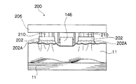
サッカー202は、図8、図9乃至図11に示すように、真空吸着用の吸盤装置として構成するもので、真空吸着用の吸盤部を平版刷版11の上端部に沿うように長細い形状(例えば、長円形状)に形成する。このサッカー202は、吸盤本体201の底部に当たる吸着面部を、長手方向に対して波打つように湾曲させて構成する。
As shown in FIGS. 8 and 9 to 11, the
すなわち、この吸盤本体201の吸着面部には、吸着平面から離間するように湾曲した変形操作用の凹部201Aを、真空ホース226が接続される吸引口部224を設ける部分に形成する。なお、このサッカー202では、吸盤本体201の吸着面の中央部に、空気を吸引するための吸引口部224を配置する。
That is, in the suction surface portion of the suction cup
さらに、この吸盤本体201の吸着面部には、吸盤本体201の長手方向両端部近くにも、変形操作用の凹部201Aを形成する。さらに隣接する変形操作用の凹部201Aの間には、湾曲した凸部201Bを滑らかにカーブして連続するよう形成し、吸盤本体201の両端に当たる変形操作用の凹部201Aの端部を凸部201Bに形成する。
Further, the suction surface portion of the
この吸盤本体201は、変形操作用の凹部201Aの最も凹んだ点と、凸部201Bの最も突出した頂点との高低差を、0.6mmから0.9mmに構成する。
The suction cup
この変形操作用の凹部201Aは、吸盤本体201で平版刷版11を吸着したときに、吸引口部224から空気を吸引したときの吸引力で変形操作用の凹部201Aの湾曲形状に添わせるよう平版刷版11を弾性変形させるためのものである。よって、この吸盤本体201には、少なくとも1つの変形操作用の凹部201Aを、真空ホース226に接続した吸引口部224がある部分に設ける。
When the
また、吸盤本体201の吸着面部には、その外周を取り囲むように一段高い枠状の当接端縁部203を一体的に形成する。さらに、この吸盤本体201の吸着面部では、当接端縁部203の内側を空気通路となる浅い溝状の底面部205に形成する。この底面部205の中央部には、吸引口部224を開口させる。
Further, the suction surface portion of the
この吸盤本体201の吸着面部には、その当接端縁部203の外周側部から斜め外方に向けてスカート部202Aを一体的に形成する。このスカート部202Aは、波形状の当接端縁部203と、平版刷版11の平面との間に介在して気密を保つ作用を奏するように比較的柔らかく構成し、かつ当接端縁部203における波形状の高低差に対応した長さを持つように構成する。このため、このスカート部202Aは、その厚さを0.3mmから0.5mmの薄いものに構成する。
On the suction surface portion of the
また、サッカー202の吸引口部224には、真空ホース226の一端部を接続し、真空ホース226の他端部を、制御部120で吸気操作を制御される吸気装置である真空ポンプ24に接続する。
Also, one end of a
このサッカー202は、制御部120で真空ポンプ24を駆動制御し真空ホース226を介してサッカー202の吸引口部224から空気を吸引することにより、スカート部202Aに囲まれた波型形状の当接端縁部203に平版刷版11の表面が密着するように吸着させ、平版刷版11が当接端縁部203の波形状に沿うように弾性変形させて、この吸着された平版刷版11とその下にある平版刷版11との隙間から容易に空気を流入させて真空密着を解除する捌き動作を適切に行うことができる。
The
また、このサッカー202では、スカート部202Aを薄く弾力を弱く構成しているので、吸盤本体201の吸着面部にある変形操作用の凹部201Aと凸部201Bとにより形成される波形形状に沿わせるように平版刷版11を吸着したときに、吸着した平版刷版11の端部がその下にある平版刷版11の表面に押し当てられて空気の侵入を妨げるように変形することを抑制し、吸着した平版刷版11とその下の平版刷版11との間に空気が入り易くすることができる。
Further, in this
なお、スカート部202Aの弾力が強いと、吸盤本体201の端部から斜め外方に向けて突出しているスカート部202Aによって、吸着されている平版刷版11の端部がその下にある平版刷版11の表面に押し当てられて吸盤形状に変形し、吸盤の作用でその下の平版刷版11を吸着する虞がある。そこで、このサッカー202では、スカート部202Aを薄く弾力を弱く構成することによって、この吸盤化現像を防止する。
When the elasticity of the
また、上述のように用いられるサッカー202は、印刷版供給カセット20内に載置された平版刷版11の束における最も上に位置する平版刷版11を、矢印A方向に持ち上げるような捌き動作を行うためのものであるので真空ポンプの一回の駆動時間が短く、空気の吸引能力も小さくて良いため、比較的小型で低出力の廉価な真空ポンプを利用することができる。
In addition, the
このように構成されたサッカー202は、複数の合紙レス平版刷版11の束における最上部位置にある搬出される平版刷版11の搬送方向先端(図で上端)から所定の短い距離(吸着対象の先端からスカートの先端までの距離)を置いた位置に吸着可能なように、ピックアップユニット200に配置する。本実施の形態では、平版刷版11の先端からスカート部202Aの先端までの距離を2mmから10mmの範囲内の距離に設定する。
The
図7に示すように、操作部材206には、その長手方向中央部に設けたU字状の切欠部内に臨むように、搬出用ローラ146を配置する。この搬出用ローラ146は、その回転軸212の両端部をそれぞれ操作部材206の裏面に突設された図示しない軸受部材に回動自由に支受させて装着する。
As shown in FIG. 7, a carry-out
図3に示すように、この枚葉供給装置12では、搬送ローラ方式の搬出手段を、搬出ローラ147と搬出用ローラ146との間に平版刷版11をニップした状態で搬出ローラ147を回転駆動することにより、平版刷版11を搬出するように構成する。
As shown in FIG. 3, in the
次に、上述した図7に示す構成のピックアップユニット200による、複数の合紙レス平版刷版11の束における最上部位置にある搬出される平版刷版11を1枚づつ分離するように捌くため、この平版刷版の枚葉供給装置で実行する枚葉分離動作と、この捌かれた平版刷版11を搬出する搬出動作について説明する。
Next, the pick-up
このピックアップユニット200は、制御部120で移動操作機構122を制御することによって、図3に矢印Aで示す昇降動作による捌き動作と、矢印Bで示す略水平方向の往復動作による捌き動作と、矢印Cで示す昇降動作による搬出のための動作とを行う。
The
このピックアップユニット200は、動作開始前に、サッカー202を搬出用ローラ146の平版刷版11に対する当接レベルから離間した所定の上昇位置に移動させた状態で待機する。
The
制御部120は、平版刷版11を一枚づつ分離して搬出する動作を開始する指令を受けると、ピックアップユニット200を制御して、図12のフローチャートに示す所定の捌き動作を行う。
When the control unit 120 receives an instruction to start the operation of separating and transporting the
この制御部120は、捌き動作の制御を開始するため移動操作機構122を駆動制御して、ピックアップユニット200を退避位置で待機している状態から、合紙レス平版刷版11の束上面に移動させる。
The control unit 120 drives and controls the
この動作の際、ピックアップユニット200では、その搬出用ローラ146が初めに最も上に位置する平版刷版11の表面に当接する。
During this operation, in the
次に、制御部120は、昇降装置210を駆動制御してサッカー202を平版刷版11の表面に圧接させて捌き動作スタート状態にセットする。
Next, the control unit 120 drives and controls the elevating
次に、制御部120は、図12のフローチャートに示す捌き動作の制御を開始し、そのステップ30の密着開始工程で、真空ポンプ24の駆動を開始する。これにより、真空ポンプ24は、駆動されて、真空ホース226を介してサッカー202の吸盤本体201に設けた吸引口部224から空気を吸引することにより、底面部205とスカート部202Aとの内部を平版刷版11の搬送方向先端側端部から所定距離だけ置いた位置の表面に吸着させる動作を開始し、次のステップ31に移行する。
Next, the control unit 120 starts the control of the whirling operation shown in the flowchart of FIG. 12, and starts driving the
このステップ31では、変形用の待機工程として、図9に示すように吸盤本体201の吸着面部にある変形操作用の凹部201Aと凸部201Bとにより形成される波形形状に吸着された平版刷版11の形状がなじむようにする、変形待ち時間(ここでは3秒間)だけその位置を保って待機してから、次のステップ32に移行する。
In this
このステップ32では、空気導入用持ち上げ工程として、制御部120が移動操作機構122を駆動制御し操作部材206を移動操作して、サッカー202と、これに吸着されている平版刷版11とを、比較的遅い速度で持ち上げて、空気が平版刷版11の間に入るきっかけを作る動作を行う。
In this
このとき、平版刷版11は、その搬送方向先端側端部近くのサッカー202に吸着された部分が当接端縁部203の波型形状に沿って弾性変形し、その下にある平版刷版11の表面との間に空気が流入可能な比較的小さな開口が開いて密着が部分的に解除された状態となる。
At this time, the
これとともに、平版刷版11は、その搬送方向先端側端部近くの全幅に渡る部分が、その中央部で搬出用ローラ146に押し下げられ、その両側部分で各サッカー202によって持ち上げられて比較的大きなウェーブを描くように十分に弾性変形して湾曲した図11に示す状態となり、サッカー202に吸着された平版刷版11とその下にある平版刷版11との間で少なくとも搬送方向先端の幅方向全体に渡って密着が全面的に解除された状態となる。
At the same time, the
次に、ステップ33へ進んで、昇降動作による捌き動作を行うあおり操作工程へ移行し、制御部120は、移動操作機構122を駆動制御しピックアップユニット200を上下に往復させるあおり操作をする。このあおり操作は、制御部120が移動操作機構122を制御して、サッカー202とこれに吸着されている平版刷版11とを、比較的に最も速い速度で、平版刷版11の表面から70mmの高さへ持ち上げてから平版刷版11の表面から20mmの高さまで持ち下げるという一連の動作を3回繰り返して平版刷版11を煽ることにより捌く動作を行う。
Next, proceeding to step 33, the process proceeds to the tilting operation step in which the lifting operation is performed, and the control unit 120 controls the
このようにサッカー202で吸着した平版刷版11に対してあおり操作を行うことによって、搬出される平版刷版11は、その先端部が比較的小さな波型形状と比較的大きなウェーブ形状とを同時に成すように弾性変形した状態で隙間を開け、その下にある平版刷版11の表面に対して全幅に渡り離間した隙間から大量の空気を取り入れながら、あおられることにより、サッカー202に吸着された平版刷版11とその下の平版刷版11との間に入った空気が平版刷版11の先端から中央部に向けて入ることにより密着を解除するように捌くので、サッカー202に吸着されている平版刷版11とその下にある平版刷版11とが密着されている状態を平版刷版11の先端から中央部にかけて解除する状態とし、次のステップ34に移行する。
By performing a tilting operation on the
ステップ34では、略水平方向の動作による捌き動作としての全面離間用の捌き工程として、制御部120が移動操作機構122を駆動制御して、サッカー202で吸着した平版刷版11を70mmの高さへ持ち上げた状態から、搬送方向下流側へ向けて略水平に150mm程度の距離だけ移動させる。
In
この平版刷版11の先端部をサッカー202で吸着して70mmの高さへ持ち上げた状態で略水平方向に150mm程度移動させる動作は、平版刷版11の厚さに対応した比較的速い所要の速度で行う。
The operation of moving the
このサッカー202で吸着された平版刷版11を搬送方向下流側へ向けて略水平に移動する動作では、搬出する平版刷版11の後端側部分とこれに隣接して印刷版供給カセット20内に残されるべき平版刷版11との間に空気が押し込まれて搬出する平版刷版11の搬送方向後端側部分の密着を解除するように捌く。
In the operation of moving the
さらに、このサッカー202で吸着された平版刷版11を搬送方向下流側へ向けて略水平に移動する動作では、搬出する平版刷版11の後端側部分の上方にある空気が希薄となって引き上げるように吸引する作用によって搬出する平版刷版11の搬送方向後端側部分をその下の平版刷版11から引き離すように捌く。
Further, in the operation of moving the
また、このサッカー202で吸着された平版刷版11は、搬送方向下流側へ向けて略水平に移動する動作によって、その全底面側が隣接する平版刷版11の表面上を離間しながら摺動することによって、全面的に密着状態が解除される。
Further, the
次に、制御部120は、ステップ35へ進んで、降下動作による搬出準備工程へ移行し、制御部120が移動操作機構122を駆動制御しピックアップユニット200を降下させて、サッカー202に吸着されている平版刷版11の先端部を、図示しない駆動モータで回動されるゴムローラ製の搬出ローラ147上におき、搬出ローラ147と搬出用ローラ146との間に平版刷版11をニップした状態とし、次のステップ36に移行する。
Next, the control unit 120 proceeds to step 35 and shifts to a carry-out preparation process by a lowering operation. The control unit 120 drives and controls the
次に、制御部120は、ステップ36へ進んで搬出工程へ移行し、制御部120が真空ポンプ24を停止させ大気に開放する電磁弁を開いてサッカー202内の負圧を大気圧に戻すことにより、サッカー202の吸着状態を解除して平版刷版11を開放し、さらに昇降装置210を駆動制御して、サッカー202を平版刷版11から離間した所定の上昇位置に移動させる。
Next, the control unit 120 proceeds to step 36 and shifts to the carry-out process, where the control unit 120 stops the
この後、制御部120は、搬出ローラ147の図示しない駆動モータを駆動制御して、搬出ローラ147と搬出用ローラ146との間にニップされた平版刷版11をインナードラム露光装置14へ搬送するための搬送ベルト巻き掛け機構へ向けて搬出する。
Thereafter, the control unit 120 drives and controls a drive motor (not shown) of the carry-out
このように、一枚の平版刷版11を搬出ローラ147と搬出用ローラ146との間にニップして搬出する場合には、平版刷版11同士が摺接して擦れ傷が発生する事態を解消できる。
As described above, when the
なお、上述した一枚の平版刷版11の搬出動作が完了すると、制御部120は、移動操作機構122を駆動制御して、ピックアップユニット200を待機位置に復帰させて次の搬送動作に備える。
When the carry-out operation of the single
すなわち、前述したピックアップユニット200を利用して平版刷版11を1枚づつ分離するように捌く枚葉分離動作と、この捌かれた平版刷版11を搬出する搬出動作では、捌き第1段階として、印刷版供給カセット20に収納された最上位の平版刷版11をサッカー202の真空吸着により吸い付け、サッカー202の吸着面を波型形状にした構成によって、平版刷版11のサッカー202が密着した直下の部分で捌く(空気流入のきっかけを作る)。
That is, the sheet separation operation for separating the
次に、この枚葉分離動作及び搬出動作では、捌き第2段階として、平版刷版11をサッカー202で吸着して持ち上げたときに、平版刷版11に吸着したサッカー202の高さ位置と、搬出用ローラ146が平版刷版11に当接する高さ位置との高低差により、平版刷版11の先端付近を捌く。
Next, in this sheet separation operation and unloading operation, as the second stage of rolling, when the
次に、この枚葉分離動作及び搬出動作では、捌き第3段階として、サッカー202で吸着した平版刷版11をピックアップユニット200の動作によって吸着面から例えば70mmの高さまで持ち上げてから20mmの高さまで持ち下げるという一連の動作を3回繰り返して平版刷版11をあおることで、密着した平版刷版11の中央付近を捌く。
Next, in this sheet separation operation and carry-out operation, as a third stage of rolling, the
次に、この枚葉分離動作及び搬出動作では、捌き第4段階として、例えば、サッカー202を吸着面から70mmの高さに位置させた状態でピックアップユニット200を略水平に移動し、搬出用ローラ146の上方で停止させる動作によって密着した平版刷版11の後端部分を捌く。
Next, in this single wafer separation operation and unloading operation, as a fourth stage of rolling, for example, the
次に、この枚葉分離動作及び搬出動作では、ピックアップユニット200を下降させて、搬出用ローラ146と搬出ローラ147とで平版刷版11をニップする状態としてから搬出ローラ147を回動して平版刷版11を搬出するという動作を行う。
Next, in this sheet separation operation and unloading operation, the
次に、上述したピックアップユニット200による、複数の合紙レス平版刷版11の束における最上部位置にある搬出される平版刷版11を1枚づつ分離して搬出する動作をより確実に実行できるようにするための手段について説明する。
Next, the operation of separating and carrying out the
この上述したピックアップユニット200による搬出動作では、サッカー202で吸着した平版刷版11を搬送方向下流側へ向けて略水平に移動する動作の際に、その下隣接する平版刷版11が引きずられて搬出される虞がある。
In the carrying-out operation by the
そこで、図5に示すように、平版刷版11をより確実に1枚づつ分離する手段では、印刷版供給カセット20における搬送方向下流側の所定位置に、サッカー202で吸着した平版刷版11の持ち上げ位置以下の所定高さを持つ突片状(壁状でも良い)のストッパ25を配置する。
Therefore, as shown in FIG. 5, in the means for separating the
このようにストッパ25を設けた場合には、サッカー202で吸着した平版刷版11を略水平に移動した際に、その下に隣接する平版刷版11が搬送方向下流側へ向けて移動しようとしても、ストッパ25に当たって制止されるので、サッカー202で吸着した平版刷版11だけをより確実に搬出できる。
When the
また、平版刷版11をより確実に1枚づつ分離する手段では、図6に示すように、印刷版供給カセット20の搬送方向下流側近傍の所定位置に、エアブロアのノズル27を配置して構成する。
Further, in the means for separating the
このように構成した場合には、サッカー202で吸着した平版刷版11を搬送方向下流側へ向けて略水平に移動する動作の際に、このサッカー202で吸着した平版刷版11とその下に隣接する平版刷版11との間に空気を吹き付けることにより、これらの間を引き剥がして離間させ、サッカー202で吸着した平版刷版11だけをより確実に搬出できる。
In the case of such a configuration, the
図2に示すように、この枚葉供給装置12では、前述したようにピックアップユニット200によって1枚だけ分離した平版刷版11を搬送ベルト巻き掛け機構へ送給する。
As shown in FIG. 2, in the
この搬送ベルト巻き掛け機構には、各平版刷版11をインナードラム露光装置14へ搬送するために、主搬送ベルト148を張架した主搬送ベルト巻き掛け機構150と、副搬送ベルト152を張架した副搬送ベルト巻き掛け機構154とを設置する。
The transport belt winding mechanism includes a main transport
この主搬送ベルト巻き掛け機構150は、平版刷版11の搬入位置から、インナードラム露光装置14への搬出位置との間に搬送ベルト148を張架して搬送路を構成する。
The main conveyor
また、副搬送ベルト巻き掛け機構154は、主搬送ベルト巻き掛け機構150における主搬送ベルト148の下側に設定される搬送路の一部を共用して搬送中の平版刷版11が脱落することを防止するよう構成する。
Further, the sub-transport
このため、副搬送ベルト巻き掛け機構154は、主搬送ベルト148における、搬出ローラ147から搬出された各平版刷版11の先端が突き当てられるガイド範囲より搬送方向下流側の中間ローラ156から、主搬送ベルト148の下側に設定される搬送路の出口に近い中間ローラ158の区間で、主搬送ベルト148と副搬送ベルト152とが添うようになって走行するよう巻き掛けて構成する。
For this reason, the sub-transport
このように構成された主搬送ベルト巻き掛け機構150では、搬出用ローラ146と搬出ローラ147とにニップされて搬出された平版刷版11の先端が、主搬送ベルト148における先端の第1ローラ151と中間ローラ156との間に張架された部分に相当するガイド範囲148Aに当たり、主搬送ベルト148の走行動作に従って中間ローラ156側へ搬送される。
In the main conveyance
そして、先端を主搬送ベルト148にガイドされた平版刷版11は、中間ローラ156の位置で、主搬送ベルト148と副搬送ベルト152との間に挟み込まれて挟持された状態で搬送路上を搬送され、出口に近い中間ローラ158の位置で挟持状態を開放され、インナードラム露光装置14へ搬入される。
Then, the
このCTPシステムにおけるインナードラム露光装置14は、円弧内周面形状(円筒内周面の一部を構成する形状)の支持体134を母体として構成されており、この支持体134の内周面に沿って平版刷版11を支持するようになっている。
The inner
このインナードラム露光装置14では、図示しない真空吸着手段によって、未記録の記録媒体である平版刷版11を支持体134の内周面に確実に密着させて沿わせた状態に保持してから露光処理を行う。
In this inner
このインナードラム露光装置14では、支持体134の円弧中心位置に、光ビーム偏向器としてのスピナーミラー装置136を配設する。このスピナーミラー装置136は、反射鏡部材(スピナーミラー)138を頂面に配置した回転軸140を、図示しない制御部のスピナードライバによって回転制御がされる駆動源としてのモータによって高速回転可能に構成する。このスピナーミラー装置136では、回転軸140の回転中心軸を支持体134の円弧中心軸と一致するように構成する。
In the inner
このスピナーミラー装置136では、光源側の光学系から投射された光ビームを、回動する反射鏡部材138の反射鏡面に反射させて平版刷版11の感光面に対して主走査方向への走査露光を行う。
In the
このスピナーミラー装置136は、図示しない副走査移動手段によって、支持体134の円弧中心軸の軸線方向(図2の表面から裏面に貫通する方向)に等速度で移動制御されることにより副走査する。
The
このためスピナーミラー装置136では、制御部のスピナードライバによって、そのモータの回転制御がされると共に、図示しない副走査移動手段により副走査方向に移動制御される。
Therefore, in the
このように構成されたスピナーミラー装置136は、光源側の光学系から投射され画像情報に応じて変調された光ビームを、回動する反射鏡部材138の反射鏡面に反射させて主走査方向への走査露光を行いながら、スピナーミラー装置136を副走査方向へ移動することによって、平版刷版11の記録面全面に対して2次元の画像を記録する処理を行う。
The
このCTPシステムに設けるバッファ装置16は、インナードラム露光装置14で露光処理された平版刷版11を、搬送速度を調整することによって所要のタイミングで現像処理装置18へ搬入する機能を有する。
The
現像処理装置18は、搬入されて来た露光済の平版刷版11に対する現像処理を行って潜像を顕像化して印刷版を製版する。
The
なお、前述した平版刷版の自動供給装置は、前述した合紙の保護を必要としないフォトポリマPS版以外に、例えば、いわゆるサーマルPS版で、表面に形成された画像を形成する記録層に傷が付くことを防止するため、記録層の最外表面上にオーバーコート層(現像前の水洗工程で完全に除去できる水溶性材料で構成されたOC層等)が塗布されているものを利用することができる。さらに、平版刷版の自動供給装置は、合紙の保護を必要とせず、じかに重ねて束ねた状態で取り扱っても傷が問題とならない程度に記録層側の表面を強化した表面強化型のサーマルPS版を利用することができる。 In addition to the photopolymer PS plate that does not require the protection of the slip sheet, the automatic lithographic printing plate supply device described above is, for example, a so-called thermal PS plate for a recording layer that forms an image formed on the surface. In order to prevent scratches, an overcoat layer (an OC layer composed of a water-soluble material that can be completely removed by a washing process before development) is applied on the outermost surface of the recording layer. can do. Furthermore, the lithographic printing plate automatic supply device does not require protection of interleaf paper, and it is a surface-enhanced thermal plate that has a surface that has been strengthened to the extent that scratches do not pose a problem even when handled in a stacked and bundled state. PS version can be used.
また、この平版刷版の自動供給装置の構成は、一般に平版印刷の分野で用いられる製版方式に対応した平版刷版である、光を利用して記録層に画像を記録する(光モード)の平版刷版、熱を利用して記録層に画像を記録する(熱モード)の平版刷版、記録層中で光を熱に変換させて画像を記録する(光、熱モード)の平版刷版、化学反応を利用した平版刷版、物理的な現像を利用した平版刷版、さらにはいわゆるコンベンショナルな平版刷版を一枚づつ分離して供給することに利用できることは勿論である。 In addition, the configuration of this lithographic printing plate automatic supply device is a lithographic printing plate that is generally compatible with a plate making method used in the field of lithographic printing, and records an image on a recording layer using light (optical mode). Lithographic printing plate, lithographic printing plate for recording an image on a recording layer using heat (thermal mode), lithographic printing plate for recording an image by converting light into heat in the recording layer (light, thermal mode) Of course, the present invention can be used to separate and supply a lithographic printing plate using a chemical reaction, a lithographic printing plate using physical development, and a so-called conventional lithographic printing plate.
10 カセットの格納装置
11 平版刷版
12 枚葉供給装置
14 インナードラム露光装置
20 印刷版供給カセット
22 カセットラック
23 カセット移動機構
25 ストッパ
27 ノズル
120制御部
122移動操作機構
146搬出用ローラ
147搬出ローラ
200ピックアップユニット
201吸盤本体
202サッカー
202A スカート部
203当接端縁部
205底面部
DESCRIPTION OF
Claims (4)
前記略水平にセットされた平版刷版の束における最も上に位置する前記平版刷版に対して、波打つように湾曲させて形成した吸着面部で吸着することにより最上位の前記平版刷版の直下の前記平版刷版が密着しないように捌くサッカーと、
前記略水平にセットされた平版刷版の束における最上位の前記平版刷版に対して転接可能に装着した搬出用ローラと、
前記サッカーで吸着した最上位の前記平版刷版を、所定高さ位置に持ち上げてから搬送方向下流側の搬出ローラ上へ横に搬送し、当該搬出ローラ上に最上位の前記平版刷版を降下させて前記搬出用ローラとの間にニップさせ、前記搬出ローラと搬出用ローラとでニップして転接することにより搬出可能とさせるように操作する移動操作手段と、
を有することを特徴とする平版刷版の自動供給装置。 In a state in which a predetermined number of the lithographic printing plates are stacked and bundled on the surface of one lithographic printing plate by bringing the back surface of the other lithographic printing plate into direct contact with each other and being held substantially horizontally A storage device set,
Immediately below the uppermost lithographic printing plate by adsorbing it to the uppermost lithographic printing plate in the bundle of lithographic printing plates set substantially horizontally, by adsorbing it on the adsorbing surface portion formed so as to wave And the football that crawls so that the lithographic printing plate of the
A carry-out roller mounted so as to be capable of rolling contact with the uppermost lithographic printing plate in a bundle of lithographic printing plates set substantially horizontally;
The uppermost lithographic printing plate adsorbed by the football is lifted to a predetermined height position and then horizontally conveyed onto a carry-out roller on the downstream side in the carrying direction, and the uppermost lithographic plate is lowered onto the carry-out roller. A moving operation means that is niped between the unloading roller and niped between the unloading roller and the unloading roller to enable unloading, and
An apparatus for automatically supplying a lithographic printing plate, comprising:
Priority Applications (2)
| Application Number | Priority Date | Filing Date | Title |
|---|---|---|---|
| JP2006070332A JP2007246205A (en) | 2006-03-15 | 2006-03-15 | Automatic feeding device for lithographic printing plate |
| PCT/JP2007/051499 WO2007086580A1 (en) | 2006-01-30 | 2007-01-30 | Automatic feeding device for lithographic printing plates |
Applications Claiming Priority (1)
| Application Number | Priority Date | Filing Date | Title |
|---|---|---|---|
| JP2006070332A JP2007246205A (en) | 2006-03-15 | 2006-03-15 | Automatic feeding device for lithographic printing plate |
Publications (1)
| Publication Number | Publication Date |
|---|---|
| JP2007246205A true JP2007246205A (en) | 2007-09-27 |
Family
ID=38590897
Family Applications (1)
| Application Number | Title | Priority Date | Filing Date |
|---|---|---|---|
| JP2006070332A Pending JP2007246205A (en) | 2006-01-30 | 2006-03-15 | Automatic feeding device for lithographic printing plate |
Country Status (1)
| Country | Link |
|---|---|
| JP (1) | JP2007246205A (en) |
Citations (8)
| Publication number | Priority date | Publication date | Assignee | Title |
|---|---|---|---|---|
| JPH04116034A (en) * | 1990-09-06 | 1992-04-16 | Fuji Photo Film Co Ltd | Sheet leafing device |
| JPH06100187A (en) * | 1992-09-24 | 1994-04-12 | Fuji Photo Film Co Ltd | Sheet sucking device |
| JPH08268587A (en) * | 1995-03-31 | 1996-10-15 | Fuji Photo Film Co Ltd | Pump for suction device |
| JPH09169442A (en) * | 1995-11-21 | 1997-06-30 | Heidelberger Druckmas Ag | Paper feed device and method for individualizing sheet |
| JP2000335765A (en) * | 1999-05-28 | 2000-12-05 | Shin Etsu Polymer Co Ltd | Feeding device for cut-plate sheet |
| JP2002128294A (en) * | 2000-10-25 | 2002-05-09 | Fuji Photo Film Co Ltd | Sucking and carrying device for printing plate |
| JP2002160837A (en) * | 2000-11-24 | 2002-06-04 | Fuji Photo Film Co Ltd | Image recording device |
| JP2003081447A (en) * | 2001-09-13 | 2003-03-19 | Fuji Photo Film Co Ltd | Lithographic printing plate laminated bundle and lithographic printing plate loading member |
-
2006
- 2006-03-15 JP JP2006070332A patent/JP2007246205A/en active Pending
Patent Citations (8)
| Publication number | Priority date | Publication date | Assignee | Title |
|---|---|---|---|---|
| JPH04116034A (en) * | 1990-09-06 | 1992-04-16 | Fuji Photo Film Co Ltd | Sheet leafing device |
| JPH06100187A (en) * | 1992-09-24 | 1994-04-12 | Fuji Photo Film Co Ltd | Sheet sucking device |
| JPH08268587A (en) * | 1995-03-31 | 1996-10-15 | Fuji Photo Film Co Ltd | Pump for suction device |
| JPH09169442A (en) * | 1995-11-21 | 1997-06-30 | Heidelberger Druckmas Ag | Paper feed device and method for individualizing sheet |
| JP2000335765A (en) * | 1999-05-28 | 2000-12-05 | Shin Etsu Polymer Co Ltd | Feeding device for cut-plate sheet |
| JP2002128294A (en) * | 2000-10-25 | 2002-05-09 | Fuji Photo Film Co Ltd | Sucking and carrying device for printing plate |
| JP2002160837A (en) * | 2000-11-24 | 2002-06-04 | Fuji Photo Film Co Ltd | Image recording device |
| JP2003081447A (en) * | 2001-09-13 | 2003-03-19 | Fuji Photo Film Co Ltd | Lithographic printing plate laminated bundle and lithographic printing plate loading member |
Similar Documents
| Publication | Publication Date | Title |
|---|---|---|
| JP4102540B2 (en) | Sheet-fed method of plate-like member | |
| EP1319616B1 (en) | Device for removing image recording material | |
| US6729837B1 (en) | Sheet feeder and sheet feeding method | |
| JP2002321840A (en) | Device for feeding printing plate sheet by sheet | |
| US7913621B2 (en) | Plate feeding apparatus and plate feeding method | |
| JP2007246205A (en) | Automatic feeding device for lithographic printing plate | |
| EP1426832A2 (en) | Image recording material conveying device and automatic image recording system | |
| JP2007008715A (en) | Automatic supply device of lithographic press plate | |
| JP2012232816A (en) | Paper sheet feeding device, and image forming apparatus with the same | |
| WO2007086580A1 (en) | Automatic feeding device for lithographic printing plates | |
| JP2007119247A (en) | Feeding device for planographic plate and sheet separation method | |
| JP2007001681A (en) | Automatic planographic printing plate feeder | |
| US6675711B2 (en) | Apparatus for feeding and ejecting a printing plate onto a surface plate | |
| JP2007022781A (en) | Automatic supply device for lithographic plate | |
| JP2007031139A (en) | Automatic supply-delivery device of lithographic plate | |
| JP2007204162A (en) | Automatic feeder for lithographic printing plate | |
| US6624840B1 (en) | Automatic exposure apparatus for printing plates and method for exposing printing plates | |
| JP2003076032A (en) | Device for conveying and guiding printing plate | |
| JPH0229029B2 (en) | ||
| JP2006176287A (en) | Automatic supply device of photosensitive printing plate | |
| JP2003276878A (en) | Image-recording material sheet carrier | |
| JP2007093739A (en) | Supply and conveying device for lithographic printing plate | |
| JP2005003713A (en) | Registering device of printing form | |
| JP2007204164A (en) | Automatic feeder of lithographic printing plate | |
| JP2007238247A (en) | Device for automatically supplying lithographic plate |
Legal Events
| Date | Code | Title | Description |
|---|---|---|---|
| A621 | Written request for application examination |
Effective date: 20080716 Free format text: JAPANESE INTERMEDIATE CODE: A621 |
|
| A131 | Notification of reasons for refusal |
Free format text: JAPANESE INTERMEDIATE CODE: A131 Effective date: 20100427 |
|
| A521 | Written amendment |
Effective date: 20100625 Free format text: JAPANESE INTERMEDIATE CODE: A523 |
|
| A02 | Decision of refusal |
Free format text: JAPANESE INTERMEDIATE CODE: A02 Effective date: 20100803 |