EP0775580A2 - Druckkopf für eine mit Bläschen angetriebene Tintenstrahldruckvorrichtung - Google Patents
Druckkopf für eine mit Bläschen angetriebene Tintenstrahldruckvorrichtung Download PDFInfo
- Publication number
- EP0775580A2 EP0775580A2 EP96308587A EP96308587A EP0775580A2 EP 0775580 A2 EP0775580 A2 EP 0775580A2 EP 96308587 A EP96308587 A EP 96308587A EP 96308587 A EP96308587 A EP 96308587A EP 0775580 A2 EP0775580 A2 EP 0775580A2
- Authority
- EP
- European Patent Office
- Prior art keywords
- heat generating
- print head
- jet printer
- bubble jet
- electrodes
- Prior art date
- Legal status (The legal status is an assumption and is not a legal conclusion. Google has not performed a legal analysis and makes no representation as to the accuracy of the status listed.)
- Withdrawn
Links
Images


Classifications
-
- B—PERFORMING OPERATIONS; TRANSPORTING
- B41—PRINTING; LINING MACHINES; TYPEWRITERS; STAMPS
- B41J—TYPEWRITERS; SELECTIVE PRINTING MECHANISMS, i.e. MECHANISMS PRINTING OTHERWISE THAN FROM A FORME; CORRECTION OF TYPOGRAPHICAL ERRORS
- B41J2/00—Typewriters or selective printing mechanisms characterised by the printing or marking process for which they are designed
- B41J2/005—Typewriters or selective printing mechanisms characterised by the printing or marking process for which they are designed characterised by bringing liquid or particles selectively into contact with a printing material
- B41J2/01—Ink jet
- B41J2/135—Nozzles
- B41J2/14—Structure thereof only for on-demand ink jet heads
- B41J2/14016—Structure of bubble jet print heads
- B41J2/14072—Electrical connections, e.g. details on electrodes, connecting the chip to the outside...
-
- B—PERFORMING OPERATIONS; TRANSPORTING
- B41—PRINTING; LINING MACHINES; TYPEWRITERS; STAMPS
- B41J—TYPEWRITERS; SELECTIVE PRINTING MECHANISMS, i.e. MECHANISMS PRINTING OTHERWISE THAN FROM A FORME; CORRECTION OF TYPOGRAPHICAL ERRORS
- B41J2/00—Typewriters or selective printing mechanisms characterised by the printing or marking process for which they are designed
- B41J2/005—Typewriters or selective printing mechanisms characterised by the printing or marking process for which they are designed characterised by bringing liquid or particles selectively into contact with a printing material
- B41J2/01—Ink jet
- B41J2/135—Nozzles
- B41J2/14—Structure thereof only for on-demand ink jet heads
- B41J2/14016—Structure of bubble jet print heads
- B41J2/14088—Structure of heating means
- B41J2/14112—Resistive element
- B41J2/1412—Shape
Definitions
- the present invention relates to a print head for a bubble jet printer, and more particularly, to a print head for a bubble jet printer which enables gray scale printing.
- a printing apparatus in which ink is discharged by heat-generated bubbles is called a bubble jet printer. That is, in the bubble jet printer, the ink is discharged via a nozzle formed in the print head by bubbles created by heating the ink by a heat generating unit installed in the print head. Accordingly, text and/or graphics can be printed on a paper. In the general print head of a bubble jet printer, ink is discharged in constant amounts.
- a print head for a bubble jet printer for improving print quality is disclosed in U.S. Patent No. 4,339,762 by Yoshiaki et al.
- the print head proposed by yoshiaki et al. has a structure in which a grooved member 10 and a substrate 20 are connected to each other and ink is discharged from spaces formed therebetween.
- the grooved member 10 has a plurality of grooves 11a, 11b, 11c, 11d, 11e and 11f which are arranged longitudinally at predetermined intervals placed between a plurality of contact surfaces 12a, 12b, 12c, 12d, 12e, 12f and 12g.
- the substrate 20 has a plurality of contact layers 24 arranged opposite the contact surfaces 12a to 12g, a plurality of electrodes 23a, 23b, 23c, 23d, 23e and 23f to which current is applied and a heat generating member 22, wherein the electrodes and the heat generating member 22 are placed between the contact layers 24. Also, there is a common electrode 21 on the substrate 20 for applying current to the heat generating member 22.
- the above print head has a complicated structure in which the volume of ink is controlled by changes of applied pulses, so that the manufacturing process therefor is difficult.
- each area of electrodes corresponding to a plurality of heat generating units is different, so that the heat generating units are of different sizes. Accordingly, the size of the discharged ink bubble is controlled, thereby providing an effect to improve the print quality.
- this technology requires a nozzle for each heat generating unit, So that integration of the print head is difficult and the manufacturing process of the head is complicated.
- a print head for a bubble jet printer comprising : a substrate having a predetermined ink chamber into which ink is supplied, a nozzle plate having a plurality of nozzles disposed above the substrate; a plurality or electrodes attached to the substrate; and a heat generating unit having a plurality of heat generating subunits each connected to the plurality of electrodes.
- each nozzle corresponds to the plurality of heat generating subunits.
- the surface areas of the heat generating subunits are different.
- the electrodes comprise: a common electrode connected to one end of at least one of the heat generating subunits; a coupling electrode for coupling the other end of the heat generating subunit connected to the common electrode to ends of the heat generating subunits which are not connected to the common electrode; and a connection electrode connected to the other ends of the heat generating subunits which are not connected to the common electrode.
- the heat generating area may be changed by selecting the electrodes connected to the heat generating units, thereby varying the size of bubbles.
- the print head for the bubble jet printer according to the present invention can control the size of bubbles to control the amount of discharged ink, so that gray scale printing can be attained.
- FIG. 3 one cell of a print head for a bubble jet printer according to the present invention is shown.
- the print head has a nozzle plate having a plurality of nozzles, a substrate, a plurality of ink chambers formed on the substrate, a plurality of electrodes attached to the substrate, and a plurality of heat generating units connected to said plurality of electrodes.
- FIGS. 3 and 4 show one cell of the print head for the bubble jet printer according to the present invention, a nozzle 31 formed on a nozzle plate 30 and a substrate 40 for forming a predetermined chamber 50 into which ink 111 is supplied. Opposite the nozzle 31 and on the substrate 40, there are a plurality of electrodes 70 to which a predetermined current is applied. Between the electrodes and the substrate 40, there is an insulation layer 80. Also, there is a heat generating unit 60 appropriately connected to the electrodes 70 on the insulation layer 80.
- the set of electrodes includes one common electrode and several coupling electrodes.
- the electrodes 70 include a common electrode 71, first, second and third coupling electrodes 72, 73 and 74, and first, second and third connection electrodes 75, 76 and 77.
- the heat generating unit 60 includes first through sixth heat generating subunits 61 through 66.
- the common electrode 71 is connected to one end of the fourth, fifth and sixth heat generating subunits 64, 65 and 66, and the first, second and third connection electrodes 75, 76 and 77 are connected to an end of each of the first, second and third heat generating subunits 61, 62 and 63, respectively.
- the first coupling electrode 72 couples the first and sixth heat generating subunits 61 and 66
- the second coupling electrode 73 couples the second and fifth heat generating subunits 62 and 65
- the third coupling electrode 74 couples the third and fourth heat generating subunits 63 and 64.
- the heat generating area of the heat generating unit 60 changes when the heat generating subunits have different areas one another. That is, the first and sixth heat generating subunits 61 and 66 are simultaneously heated when power is applied to the first connection electrode 75, the second and fifth heat generating subunits 62 and 65 are simultaneously heated when power is applied to the second connection electrode 76, and the third and fourth heat generating subunits 63 and 64 are simultaneously heated when power is applied to the third connection electrode 77.
- the first and sixth heat generating subunits 61, 66 or the first, second, fifth and sixth heat generating subunits 61, 62, 65, 66 or the first, second, third, fourth, fifth, and sixth heat generating subunits 61, 62, 63, 64, 65, 66 are heated respectively.
- selecting the number of connection electrodes from the heat generating unit can change the number of the heat generating subunits resulting in the modulation of the heat generating area.
- the electrodes 70 connected to the heat generating unit 60, the first through sixth heat generating subunits 61 to 66, can be arranged in the same plane without being overlapped. If the heat generating unit 60 is manufactured by overlapping the heat generating subunits 61 to 66, the manufacturing cost is increased and the manufacturing process is complicated.
- the nozzle 31 and the heat generating unit 60 are positioned opposite each other such that the ink discharge direction through the nozzle 31 is perpendicular to the surface of heat generating unit 60.
- a nozzle 53 may be formed at one end of the ink chamber 50 such that the surface of heat generating unit 60 is co-linear to the ink discharge direction through the nozzle 53. In this case, the direction of the nozzle 53 is perpendicular to the plane of the heat generating unit 60.
- a protection layer 55 (see FIG. 3) for protecting the heat generating unit 60 from the ink 111, made of a compound including Ta, Si 3 N 4 and SiC, is formed on the heat generating unit 60.
- the heat generating subunits 61-66 of the heat generating unit 60 may be made of Ta-Al alloy or HfB 2
- the electrodes 70 may be made of Al-Cu alloy.
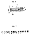
- ink bubbles of varying sizes may be obtained by varying the sizes of heat generating subunits 61', 62' and 63' as shown in FIG. 5.
- a pixel formed of four dots having a matrix structure can be printed in eleven scales of gray as shown in FIG. 7. That is, when a pixel is printed while the dots form a matrix structure, for example, when a pixel comprised of a 2x2 matrix and having two dot sizes whose diameter ratio is 1:3, is used, printing in eleven gray scales can be attained.
- the heating area of the heat generating unit is controlled, so that the size of the ink bubbles discharged via a nozzle can be controlled. As a result, the printing can be attained in various gray scales.
Landscapes
- Particle Formation And Scattering Control In Inkjet Printers (AREA)
Applications Claiming Priority (4)
| Application Number | Priority Date | Filing Date | Title |
|---|---|---|---|
| KR1019950043906A KR970025962A (ko) | 1995-11-27 | 1995-11-27 | 잉크제트 프린팅장치 |
| KR4390695 | 1995-11-27 | ||
| KR4511896 | 1996-10-10 | ||
| KR1019960045118A KR100450779B1 (ko) | 1995-11-27 | 1996-10-10 | 버블제트프린터 |
Publications (2)
| Publication Number | Publication Date |
|---|---|
| EP0775580A2 true EP0775580A2 (de) | 1997-05-28 |
| EP0775580A3 EP0775580A3 (de) | 1997-10-22 |
Family
ID=26631426
Family Applications (1)
| Application Number | Title | Priority Date | Filing Date |
|---|---|---|---|
| EP96308587A Withdrawn EP0775580A3 (de) | 1995-11-27 | 1996-11-27 | Druckkopf für eine mit Bläschen angetriebene Tintenstrahldruckvorrichtung |
Country Status (2)
| Country | Link |
|---|---|
| EP (1) | EP0775580A3 (de) |
| JP (1) | JPH09164683A (de) |
Cited By (3)
| Publication number | Priority date | Publication date | Assignee | Title |
|---|---|---|---|---|
| EP1356937A3 (de) * | 2002-04-23 | 2004-01-14 | Canon Kabushiki Kaisha | Tintenstrahlkopf |
| US6749290B2 (en) | 2001-09-04 | 2004-06-15 | Canon Kabushiki Kaisha | Recording unit, image recording apparatus and image recording method |
| WO2019044631A1 (en) * | 2017-08-31 | 2019-03-07 | Canon Kabushiki Kaisha | APPARATUS FOR MANUFACTURING LIQUID CONTAINING EXTRAFINE BUBBLES AND METHOD OF MANUFACTURING |
Families Citing this family (1)
| Publication number | Priority date | Publication date | Assignee | Title |
|---|---|---|---|---|
| KR970025962A (ko) * | 1995-11-27 | 1997-06-24 | 김광호 | 잉크제트 프린팅장치 |
Citations (3)
| Publication number | Priority date | Publication date | Assignee | Title |
|---|---|---|---|---|
| US4339762A (en) | 1979-04-02 | 1982-07-13 | Canon Kabushiki Kaisha | Liquid jet recording method |
| US4503444A (en) | 1983-04-29 | 1985-03-05 | Hewlett-Packard Company | Method and apparatus for generating a gray scale with a high speed thermal ink jet printer |
| US5121143A (en) | 1988-09-14 | 1992-06-09 | Graphtec Corp. | Ink printing head with variable-size heat elements |
Family Cites Families (6)
| Publication number | Priority date | Publication date | Assignee | Title |
|---|---|---|---|---|
| DE2945658A1 (de) * | 1978-11-14 | 1980-05-29 | Canon Kk | Fluessigkeitsstrahl-aufzeichnungsverfahren |
| EP0124312A3 (de) * | 1983-04-29 | 1985-08-28 | Hewlett-Packard Company | Widerstandsanordnungen für thermische Tintenstrahldrucker |
| US4965594A (en) * | 1986-02-28 | 1990-10-23 | Canon Kabushiki Kaisha | Liquid jet recording head with laminated heat resistive layers on a support member |
| JPS62261452A (ja) * | 1986-05-09 | 1987-11-13 | Canon Inc | 多値化記録方式 |
| JP2836749B2 (ja) * | 1989-05-09 | 1998-12-14 | 株式会社リコー | 液体噴射記録ヘッド |
| JPH03239563A (ja) * | 1990-02-17 | 1991-10-25 | Mitsubishi Electric Corp | サーマルヘツド |
-
1996
- 1996-11-21 JP JP31078296A patent/JPH09164683A/ja active Pending
- 1996-11-27 EP EP96308587A patent/EP0775580A3/de not_active Withdrawn
Patent Citations (3)
| Publication number | Priority date | Publication date | Assignee | Title |
|---|---|---|---|---|
| US4339762A (en) | 1979-04-02 | 1982-07-13 | Canon Kabushiki Kaisha | Liquid jet recording method |
| US4503444A (en) | 1983-04-29 | 1985-03-05 | Hewlett-Packard Company | Method and apparatus for generating a gray scale with a high speed thermal ink jet printer |
| US5121143A (en) | 1988-09-14 | 1992-06-09 | Graphtec Corp. | Ink printing head with variable-size heat elements |
Non-Patent Citations (1)
| Title |
|---|
| "SPSE Third International Congress on Advances in Non-Impact Printing Technologies, San Francisco, Aug. 24-28, 1986", 1986, article SUZUKI ET AL. |
Cited By (5)
| Publication number | Priority date | Publication date | Assignee | Title |
|---|---|---|---|---|
| US6749290B2 (en) | 2001-09-04 | 2004-06-15 | Canon Kabushiki Kaisha | Recording unit, image recording apparatus and image recording method |
| EP1356937A3 (de) * | 2002-04-23 | 2004-01-14 | Canon Kabushiki Kaisha | Tintenstrahlkopf |
| US6984025B2 (en) | 2002-04-23 | 2006-01-10 | Canon Kabushiki Kaisha | Ink jet head |
| WO2019044631A1 (en) * | 2017-08-31 | 2019-03-07 | Canon Kabushiki Kaisha | APPARATUS FOR MANUFACTURING LIQUID CONTAINING EXTRAFINE BUBBLES AND METHOD OF MANUFACTURING |
| US11938503B2 (en) | 2017-08-31 | 2024-03-26 | Canon Kabushiki Kaisha | Ultrafine bubble-containing liquid manufacturing apparatus and manufacturing method |
Also Published As
| Publication number | Publication date |
|---|---|
| EP0775580A3 (de) | 1997-10-22 |
| JPH09164683A (ja) | 1997-06-24 |
Similar Documents
| Publication | Publication Date | Title |
|---|---|---|
| US6030065A (en) | Printing head and inkjet printer | |
| EP0709213B1 (de) | Verfahren und Vorrichtung für Korrektionskopf und Drucker mit diesem Kopf | |
| CN100436138C (zh) | 采用具有多个喷墨加热器的喷墨头的喷墨设备 | |
| US5353051A (en) | Recording apparatus having a plurality of recording elements divided into blocks | |
| US7300137B2 (en) | Liquid-discharge recording head | |
| US5956056A (en) | Ink jet recording apparatus and method of recording with separated image data | |
| EP1935655B1 (de) | Substrat für einen Tintenstrahldruckkopf | |
| US20020057309A1 (en) | Printer and printer head | |
| US7207650B2 (en) | Apparatus and method for discharging liquid | |
| EP1428665B1 (de) | Flüssigkeitsausstosskopfsvorrichtung und Verfahren | |
| EP0517520B1 (de) | Farbstrahlaufzeichnungsverfahren und Vorrichtung | |
| EP1116589B1 (de) | Tintenstrahldruckverfahren und Tintenstrahldrucker | |
| EP1287995B1 (de) | Flüssigkeitsausstosskopf und damit versehene Bilderzeugungsvorrichtung | |
| JP2000141632A (ja) | プリンタ | |
| EP1356937B1 (de) | Tintenstrahlkopf | |
| JP5230084B2 (ja) | インクジェット記録ヘッド | |
| US5638100A (en) | Ink jet and ink preliminary ejecting method | |
| JPH0332844A (ja) | 液体噴射記録ヘッド | |
| US7588317B2 (en) | Printing apparatus, printhead, and driving method therefor | |
| JPH05261941A (ja) | インクジェット記録方法及びインクジェット記録ヘッド | |
| US20040217997A1 (en) | Fluid ejection device | |
| JPH09164683A (ja) | バブルジェットプリンタ用印刷ヘッド | |
| KR100450779B1 (ko) | 버블제트프린터 | |
| JP3849634B2 (ja) | 液体噴射装置 | |
| US6315378B1 (en) | Printing apparatus and printing method |
Legal Events
| Date | Code | Title | Description |
|---|---|---|---|
| PUAI | Public reference made under article 153(3) epc to a published international application that has entered the european phase |
Free format text: ORIGINAL CODE: 0009012 |
|
| AK | Designated contracting states |
Kind code of ref document: A2 Designated state(s): DE FR GB IT NL |
|
| PUAL | Search report despatched |
Free format text: ORIGINAL CODE: 0009013 |
|
| AK | Designated contracting states |
Kind code of ref document: A3 Designated state(s): DE FR GB IT NL |
|
| STAA | Information on the status of an ep patent application or granted ep patent |
Free format text: STATUS: THE APPLICATION IS DEEMED TO BE WITHDRAWN |
|
| 18D | Application deemed to be withdrawn |
Effective date: 19980423 |