EP0774992B1 - Multifunktions-rueckschlagventil - Google Patents
Multifunktions-rueckschlagventil Download PDFInfo
- Publication number
- EP0774992B1 EP0774992B1 EP94922152A EP94922152A EP0774992B1 EP 0774992 B1 EP0774992 B1 EP 0774992B1 EP 94922152 A EP94922152 A EP 94922152A EP 94922152 A EP94922152 A EP 94922152A EP 0774992 B1 EP0774992 B1 EP 0774992B1
- Authority
- EP
- European Patent Office
- Prior art keywords
- housing
- control valve
- valve
- pressure
- cylindrical section
- Prior art date
- Legal status (The legal status is an assumption and is not a legal conclusion. Google has not performed a legal analysis and makes no representation as to the accuracy of the status listed.)
- Expired - Lifetime
Links
Images

Classifications
-
- A—HUMAN NECESSITIES
- A61—MEDICAL OR VETERINARY SCIENCE; HYGIENE
- A61M—DEVICES FOR INTRODUCING MEDIA INTO, OR ONTO, THE BODY; DEVICES FOR TRANSDUCING BODY MEDIA OR FOR TAKING MEDIA FROM THE BODY; DEVICES FOR PRODUCING OR ENDING SLEEP OR STUPOR
- A61M39/00—Tubes, tube connectors, tube couplings, valves, access sites or the like, specially adapted for medical use
- A61M39/22—Valves or arrangement of valves
- A61M39/24—Check- or non-return valves
-
- F—MECHANICAL ENGINEERING; LIGHTING; HEATING; WEAPONS; BLASTING
- F16—ENGINEERING ELEMENTS AND UNITS; GENERAL MEASURES FOR PRODUCING AND MAINTAINING EFFECTIVE FUNCTIONING OF MACHINES OR INSTALLATIONS; THERMAL INSULATION IN GENERAL
- F16K—VALVES; TAPS; COCKS; ACTUATING-FLOATS; DEVICES FOR VENTING OR AERATING
- F16K15/00—Check valves
- F16K15/14—Check valves with flexible valve members
- F16K15/144—Check valves with flexible valve members the closure elements being fixed along all or a part of their periphery
- F16K15/147—Check valves with flexible valve members the closure elements being fixed along all or a part of their periphery the closure elements having specially formed slits or being of an elongated easily collapsible form
-
- F—MECHANICAL ENGINEERING; LIGHTING; HEATING; WEAPONS; BLASTING
- F16—ENGINEERING ELEMENTS AND UNITS; GENERAL MEASURES FOR PRODUCING AND MAINTAINING EFFECTIVE FUNCTIONING OF MACHINES OR INSTALLATIONS; THERMAL INSULATION IN GENERAL
- F16K—VALVES; TAPS; COCKS; ACTUATING-FLOATS; DEVICES FOR VENTING OR AERATING
- F16K24/00—Devices, e.g. valves, for venting or aerating enclosures
- F16K24/04—Devices, e.g. valves, for venting or aerating enclosures for venting only
-
- A—HUMAN NECESSITIES
- A61—MEDICAL OR VETERINARY SCIENCE; HYGIENE
- A61M—DEVICES FOR INTRODUCING MEDIA INTO, OR ONTO, THE BODY; DEVICES FOR TRANSDUCING BODY MEDIA OR FOR TAKING MEDIA FROM THE BODY; DEVICES FOR PRODUCING OR ENDING SLEEP OR STUPOR
- A61M39/00—Tubes, tube connectors, tube couplings, valves, access sites or the like, specially adapted for medical use
- A61M39/22—Valves or arrangement of valves
- A61M39/24—Check- or non-return valves
- A61M2039/242—Check- or non-return valves designed to open when a predetermined pressure or flow rate has been reached, e.g. check valve actuated by fluid
-
- A—HUMAN NECESSITIES
- A61—MEDICAL OR VETERINARY SCIENCE; HYGIENE
- A61M—DEVICES FOR INTRODUCING MEDIA INTO, OR ONTO, THE BODY; DEVICES FOR TRANSDUCING BODY MEDIA OR FOR TAKING MEDIA FROM THE BODY; DEVICES FOR PRODUCING OR ENDING SLEEP OR STUPOR
- A61M39/00—Tubes, tube connectors, tube couplings, valves, access sites or the like, specially adapted for medical use
- A61M39/22—Valves or arrangement of valves
- A61M39/24—Check- or non-return valves
- A61M2039/2426—Slit valve
-
- A—HUMAN NECESSITIES
- A61—MEDICAL OR VETERINARY SCIENCE; HYGIENE
- A61M—DEVICES FOR INTRODUCING MEDIA INTO, OR ONTO, THE BODY; DEVICES FOR TRANSDUCING BODY MEDIA OR FOR TAKING MEDIA FROM THE BODY; DEVICES FOR PRODUCING OR ENDING SLEEP OR STUPOR
- A61M39/00—Tubes, tube connectors, tube couplings, valves, access sites or the like, specially adapted for medical use
- A61M39/22—Valves or arrangement of valves
- A61M39/26—Valves closing automatically on disconnecting the line and opening on reconnection thereof
- A61M2039/266—Valves closing automatically on disconnecting the line and opening on reconnection thereof where the valve comprises venting channels, e.g. to insure better connection, to help decreasing the fluid space upon disconnection, or to help the fluid space to remain the same during disconnection
Definitions
- the present invention is in the field of multi-function valves. More particularly, the present invention relates to a multi-function valve having particular utility in the performance of open-heart surgery. Still more particularly, the present invention relates to a multi-function valve useful during open heart surgery for controlling aspirated fluid flow from the left ventricle of the heart to an aspiration pump by controlling the level of aspiration suction applied at the heart, for preventing inadvertent reverse flow of fluid to the heart, for safely and controllably venting reverse flow positive pressure which would cause such reverse flow of fluid to the heart, and for controlling inlet positive pressure at the control valve, which inlet positive pressure causes conventional control valves to undesirably weep patient's blood into the operating room environment.
- the heart In the performance of open heart surgery, generally the heart is bypassed and the patient's blood circulation is maintained by use of a heart-lung machine. However, a certain amount of blood finds its way into the left ventricle of the heart. Unless this blood is removed, the left ventricle of the heart is distended and resuscitation of the heart at the conclusion of the procedure is made more difficult or impossible.
- a drain tube into the left ventricle and use a positive-displacement aspiration pump to remove the accumulated blood.
- the speed of operation of such a pump positive-displacement aspiration pump determines the rate at which the pump will aspirate blood from the left ventricle.
- An insufficient rate of aspiration can still allow blood to accumulate in the left ventricle.
- an excessive aspiration rate may cause the drain tube to suck against the heart tissues, thereby causing trauma.
- One former but currently unpopular solution to this problem is to have the speed of the positive-displacement aspiration pump controlled by a technician. However, this solution requires additional operating room personnel and requires additional communication from the physician to the technician.
- a positive-displacement aspiration pump for example, a pump of the roller type
- a pre-set negative pressure relief valve is generally disposed in the suction line between the heart and the positive-displacement aspiration pump. This valve controls the suction applied to the heart by venting ambient air into the suction line downstream of the valve.
- Such a suction control valve may also include a check valve safety feature which prevents reverse flow of fluid toward the heart in the event that plumbing is connected incorrectly during the procedure, or should the aspiration pump be operated in reverse, or should the aspiration pump be stopped with a pressurized reservoir downstream of the pump, for example, causing a positive pressure reverse flow toward the heart.
- control valve may also include a positive pressure venting feature which relieves such a reverse flow positive pressure. This feature insures that aspiration plumbing is not blown apart by such a reverse positive pressure. Also, this venting feature insures that the valve itself is not overcome by a sufficiently high reverse positive pressure such that fluid forces its way past the valve and to the heart.
- the controlled venting of blood at the control valve when necessary to vent such an unintended reverse positive pressure is an acceptable operational aspect of the conventional control valves.
- this positive pressure relief safety feature does function it is the result of an infrequent personnel or equipment error which could be catastrophic for the patient.
- the venting of patient blood into the operating room environment because of a very infrequent reverse flow positive pressure of such magnitude is an accepted and necessary safety function.
- the operating room personnel will have arrange the plumbing and the location of the control valve to minimize the risk from this venting function, should it occur. That is, the blood vented from the control valve is generally arranged at a controlled location near the floor of the operating room, and the venting is preferably at a relatively low velocity so that spray and misting of blood into the operating room air is avoided.
- a physician or another person must adjust the control valve to set the venting level necessary to maintain a desired suction at the heart in view of the operating speed and pumping characterists of the aspiration pump.
- This set venting level continuously admits atmospheric air to the passage leading to e aspiration pump and results in an undesirably large amount of air being mixed with the aspirated blood.
- the venting function is set and does not self-adjust in the event the speed of the aspiration pump, or other such factor which affects the level of suction at the heart, changes during the surgical procedure.
- this control valve uses a sleeve-type of positive pressure relief valve which does properly and controllably vent reverse flow positive pressure should such a pressure be applied to the valve.
- the direction of discharge and velocity of the vented blood are not predictable or controlled.
- the control valve taught by this patent uses an umbrella-type of negative pressure relief valve so that the physician does not need to adjust the valve to control the maximum suction level applied to the patient's heart.
- This umbrella type valve is disposed in a chamber situated laterally of and communicating with the main fluid flow path through the valve.
- control valve according to the '266 patent still uses the familiar sleeve type valve for positive pressure relief so that the disadvantage of unintended release of patient's blood into the operating room from the control valve because of an inlet positive pressure is still present.
- Still another control valve is seen in two related United States patents, 4,502,502; and 4,671,786, issued 5 March 1985, and 9 June 1987, respectively, to J. Krug. These control valves use the familiar duck bill valve member to perform the check valve function. Also, the negative pressure relief valving function is performed by an umbrella valve member disposed in a lateral chamber like that seen in the '224 patent to Siposs. However, the positive pressure relief valving function is performed by a second umbrella valve controlling communication outwardly from this lateral chamber to ambient.
- control valves taught by the Krug '502, and '786 patents also suffer from the undesirable weeping or dribbling of patient's blood into the operating room environment because of an inlet positive pressure created by a fluid column pressure in the aspiration tubing, as was discussed earlier. That is, the choice of an umbrella type of positive pressure relief valve does not eliminate this problem of all of the conventional control valves discussed herein.
- the conventional control valves all accept the necessary controlled venting of blood which could result in the unlikely event of incorrect plumbing connection, reverse operation of the aspiration pump, or stopping of the pump with a pressurized reservoir downstream of the pump causing pressurized blood backflow.
- these occurrences are rare, and the safety function of the valve is necessary to prevent catastrophic injury to the patient.
- control valves seem by their designs to accept the inevitability of unpredictable venting of patient's blood if a reverse flow positive pressure level applied to the valve reaches the venting pressure level. That is, this safety venting feature is accepted as necessary, but the consequences of this feature operating are not dealt with in the designs of conventional control valves.
- a control valve should allow this venting only in a fashion best preserving safety for surrounding operating room personnel.
- an object for this invention is to provide a multi-function control valve which avoids projections on the housing of the valve which could catch on environmental tubing, wiring, and cables in the operating room.
- the present invention provides a multi-function control valve having an elongate housing defining an inlet at one end thereof, an outlet at an opposite end thereof, and a flow path extending between the inlet and outlet to communicate a flow of aspirated patient blood therebetween, a multi-function valve member sealingly disposed in the flow path and including a check valve feature preventing fluid flow from the outlet to the inlet, a vent port opening outwardly from the flow path downstream of the check valve feature, the multi-function valve member including a pressure-responsive yieldable member sealingly cooperating with the housing to prevent fluid flow through the vent passage, the yieldable member comprising a cylindrical section of elastomeric material extending along the flow path and the cylindrical section comprising an inner surface and an outer surface, and further comprising a first pressure-responsive area on the outer surface of the cylindrical section communicating with the inlet port but isolated from the outlet port by the check valve feature, the yieldable member on the one hand yielding in response to a certain level of negative pressure in said flow path to admit ambient air thereto,
- the cylindrical section of elastomeric material further defines a radially outwardly extending circumferential rib which sealingly cooperates with the housing, or the housing defines a radially inwardly extending circumferential rib sealingly cooperating with said cylindrical section of elastomeric material.
- the valve member takes the form of a duck bill check valve member with a slightly elongated cylindrical portion which inwardly defines a pressure-responsive area communicating with the inlet port but isolated from the outlet port by the check valve lips of the duck bill valve.
- the duck bill valve member outwardly sealingly cooperates with the housing at the vent port to control fluid flow through this vent port.
- the duck bill member also defines a pressure responsive area communicating with the vent port. Consequently, when the negative pressure (suction) within the flow path reaches a determined level, the cylindrical portion of the duck bill valve member unseals from the housing to allow entry of ambient air.
- An additional advantage of the present invention resides in the multi-functional aspect of its few component parts. That is, the entire functional repertoire of the control valve, including a check valve function, a positive pressure relief function, a negative pressure relief function, and a positive pressure containment function when the positive pressure is communicated to the inlet of the control valve, is achieved with a structure preferably having a total of three parts. That is, the housing of the valve may preferably be made of two sealingly cooperating parts, which define the inlet, outlet, and vent ports, and which sealingly capture the slightly elongated duck bill valve member therebetween.
- the present control valve in addition to achieving a function not provided by the conventional control valves (inlet positive pressure containment), the present control valve has a sleek housing outer configuration without external projections which could catch surrounding tubing, wires or other operating room fixtures. Accordingly, the present invention provides a control valve which is safer in several respects for the personnel of the operating room, as well as for the patient under their care.
- the present control valve allows blood to be vented therefrom in the event that reverse flow positive pressure reaches a venting pressure level, but only along a controlled and predictable path, and with a reduced flow velocity which prevents splashing and blood misting into the air.
- a multi-function control valve 10 is schematically shown in a use environment, such as an operating room.
- a patient In the operating room, a patient is undergoing open heart surgery, and the patient's heart 12 has inserted into the left ventricle 14 thereof a suction tube 16 having an open distal end 18. From the operating table, the suction tube 16 leads downwardly to a roller type of positive displacement aspiration pump 20, and to a cardiotomy reservoir 22.
- the blood and other patient fluids collected in the cardiotomy reservoir 22 is generally filtered and is otherwise treated before being reintroduced into the patient's circulatory system during or at the conclusion of the surgical procedure.
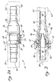
- FIGS 2 show the control valve 10 at a much enlarged scale, and in cross section in Figure 2B.
- the control valve 10 includes an elongate cylindrical two-part housing, generally referenced with the numeral 24.
- the housing 24 includes an inlet part 26, and an axially disposed outlet part 28.
- the inlet part 26 defines a pair of axially extending barbed lugs 30, which are removably captured in a respective pair of axially apertured bosses 32 defined by the outlet part 28.
- the inlet housing part 26 defines a pair of axially and circumferentially extending wall portions 34 extending over and spaced radially outwardly of an underlying wall portion 36 of the outlet housing part 28 and parallel with the lugs 30.
- the wall portions 34 and underlying wall portion 36 of the outlet housing part 28 define a radially and axially extending gap 38 opening axially toward the remainder of the outlet part 28. Consequently, as is well illustrated in Figure 2A, the control valve 10 outwardly presents a sleek cylindrical exterior shape which is only slightly stepped and is substantially without external projections which might catch on other surrounding items. This sleekness of the control valve is especially evident when suction tubing 16 is joined to the housing 24, as can be easily visualized from the dashed lines on Figure 2A. Also, the housing 24 is simply snapped together during manufacture of the control valve 10 by inserting the lugs 30 into the bosser 32 and moving the housing portions 26, 28 axially together.
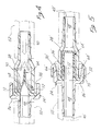
- the housing 24 includes opposite inlet and outlet ends, 40, 42, at which respective inlet and outlet openings 44, 46 are defined. Extending between and communicating the openings 44, and 46, is a flow path, generally referenced with the numeral 48.
- the flow path 48 is cooperatively defined by respective aligned bores 50, and 52 of the inlet and outlet parts 26, and 28. Outwardly, the inlet part and outlet part 26, 28, each define a respective hose barb feature, referenced with the numerals 54, and 56.
- a radially outwardly extending flange portion 62 of a multi-function yieldably shape-retaining elastomeric valving member is a radially outwardly extending flange portion 62 of a multi-function yieldably shape-retaining elastomeric valving member, generally referenced with the numeral 64 (viewing also Figure 6).
- This valving member 64 includes an axially extending cylindrical portion 66, which extends axially from the flange portion into the bore 52 of the outlet part 28, and which is radially spaced inwardly thereof. Spaced from the flange 62, the valving member 64 defines a radially outwardly extending circumferentially continuous rib 68 which sealingly engages the wall portion 36 of the outlet housing part 28. Consequently, the valving member 64 cooperates with the housing 24 to define an annular chamber 70.
- Wall portion 36 of outlet housing part 28 defines at least a single radially extending vent port 72 opening outwardly from the chamber 70 into the gap space
- the valving member 64 Downstream of the rib 68 with respect to blood flow through the valve 10 (that is, rightwardly viewing Figure 2B), the valving member 64 includes a duck bill type of check valve feature, generally referenced with the numeral 74.
- This duck bill check valve feature includes a pair of juxtaposed yieldable lips 76 which sealingly cooperate with one another at a sealing line 78.
- the cylindrical portion 66 defines an area 82 which is exposed to the negative pressure within flow path 48.
- the cylindrical portion 66 defines an area 84 within chamber 70 which is exposed to ambient pressure via the vent port 72.
- the cylindrical portion 66 defines a pair of opposed pressure-responsive areas, one of which is exposed to pressure within flow path 48, and the other of which is exposed to ambient pressure.
- the cylindrical portion 66 of the valving member 64 collapses to unseal rib 68 from wall portion 36.
- the vented blood is received into the gap 38 and against the outer wall portion 34.
- the gap 38 has a considerably larger cross sectional flow area than does the port 72 so that the flow velocity of the vented blood is greatly reduced.
- the gap 38 directs the vented blood at a relatively low velocity along the housing portion 36 and tubing 52 axially.
- This housing portion and tubing provide a flow surface along which the blood will flow without spraying or misting into the operating room environment.
- the present control valve 10 performs an inlet positive pressure containment function which is totally lacking from the conventional control valves heretofore available for use in situations of open heart and other surgical procedures. Only under conditions of outlet positive pressure relieving, which is an essential safety function for the multi-function valve 10, will any blood be vented from the present inventive control valve. When such a situation of outlet positive pressure relieving does occur, as explained above, the present valve provides the additional advantage that the vent port 72 opens toward the wall portion 34 into the relatively larger annular gap 38 so that the velocity of the venting blood is reduced and a blood spray is avoidea.
- the gap 38 itself opens axially along the line of the suction tubing 16 downstream of the control valve 10 so that the venting fluid is directed to flow along the exterior surface of the valve 10 at a low velocity, and will simply flow onto the operating room floor without spitting or spraying about.
- Figure 5 depicts an alternative embodiment of the inventive control valve.
- the duck bill valving member 64' includes a cylindrical portion 66' extending into the outlet part 28' of the control valve 10'.
- This cylindrical portion 66' is outwardly smooth, but the housing wall portion 36' defines a radially inwardly and circumferentially continuous rib 68', which sealingly cooperates with the valving member 64' to define a chamber 70'.
- the embodiment of Figure 5 is the same as that described above.
Landscapes
- Engineering & Computer Science (AREA)
- General Engineering & Computer Science (AREA)
- Health & Medical Sciences (AREA)
- Mechanical Engineering (AREA)
- Heart & Thoracic Surgery (AREA)
- Hematology (AREA)
- Anesthesiology (AREA)
- Biomedical Technology (AREA)
- Pulmonology (AREA)
- Life Sciences & Earth Sciences (AREA)
- Animal Behavior & Ethology (AREA)
- General Health & Medical Sciences (AREA)
- Public Health (AREA)
- Veterinary Medicine (AREA)
- External Artificial Organs (AREA)
- Self-Closing Valves And Venting Or Aerating Valves (AREA)
- Check Valves (AREA)
- Infusion, Injection, And Reservoir Apparatuses (AREA)
Claims (10)
- Multifunktions-Steuerventil (10) mit:einem Gehäuse (24), das einen Einlass (40), einen Auslass (42) und einen Durchflussweg (48) zwischen dem Einlass und dem Auslass zum Hindurchlassen eines Fluidflusses dazwischen definiert;einem Multifunktions-Ventilelement (64), das im Durchflussweg (48) dichtend angeordnet ist und ein Rückschlagventilmerkmal (74) aufweist, das einen Fluidfluss vom Auslass zum Einlass verhindert;wobei das Gehäuse (24) eine Lüftungsöffnung (72) definiert, die sich hinter dem Rückschlagventilmerkmal (74) vom Durchflussweg (48) nach außen öffnet;wobei das Multlfunktions-Ventilelement (64) ein auf Druck reagierendes nachgiebiges Element aufweist, das mit dem Gehäuse dichtend zusammenwirkt, um einen Fluidfluss durch die Lüftungsöffnung zu verhindern, wobei das nachgiebige Element einen zylindrischen Abschnitt (66) aus Elastomermaterial aufweist, das sich entlang des Durchflusswegs (48) erstreckt, wobei der zylindrische Abschnitt eine Innenoberfläche und eine Außenoberfläche aufweist, wobei das nachgiebige Element weiter einen ersten auf Druck reagierenden Bereich (84) auf der Außenoberfläche des zylindrischen Abschnitts aufweist, der mit der Umgebung kommuniziert, einen zweiten auf Druck reagierenden Bereich (82) auf der Innenoberfläche des zylindrischen Abschnitts, der mit dem Einlass (40) kommuniziert und durch das Rückschlagventilmerkmal (74) gegenüber dem Auslass (42) abgedichtet ist, wobei das nachgiebige Element in Reaktion auf einen festgestellten Druckpegel auf dem Rückschlagventilmerkmal zum Öffnen der Lüftungsöffnung (72) nachgibt;wobei das auf Druck reagierende Element einerseits in Reaktion auf einen bestimmten Pegel eines Unterdrucks im Durchflussweg (48) nachgibt, um über die Lüftungsöffnung (72) Umgebungsluft einzulassen, und das nachgiebige Element andererseits in Reaktion auf den festgestellten Pegel eines unter Druck stehenden Fluids nachgibt, das mit dem Auslass (42) kommuniziert, um unter Druck stehendes Fluid aus der Lüftungsöffnung (72) auszulassen; wobei unter Druck stehendes Fluid, das mit dem Einlass kommuniziert und über das Rückschlagventilmerkmal mit dem Auslass kommuniziert, ebenfalls auf den zweiten auf Druck reagierenden Bereich einwirkt, um das nachgiebige Element in einem Dichtungsverhältnis mit dem Gehäuse zu halten, wodurch unter Druck stehendes Fluid, das mit dem Einlass kommuniziert, nicht ausgelassen wird;dadurch gekennzeichnet, dass der zylindrische Abschnitt (66) aus Elastomermaterial eine sich radial nach außen erstreckende umlaufende Rippe (68) definiert, die mit dem Gehäuse (24) dichtend zusammenwirkt, oder das Gehäuse (24) eine sich radial nach innen erstreckende umlaufende Rippe definiert, die mit dem zylindrischen Abschnitt (66) aus Elastomermaterial dichtend zusammenwirkt.
- Steuerventil (10) nach Anspruch 1, bei dem der zylindrische Abschnitt (66) aus Elastomermaterial an dessen vorderem Ende vom Gehäuse (24) dichtend gehalten wird und bei dem an dessen hinterem Ende der zylindrische Abschnitt aus Elastomermaterial das Rückschlagventilmerkmal (74) trägt.
- Steuerventil (10) nach Anspruch 2, bei dem das Rückschlagventilmerkmal (74) ein Paar nachgiebiger Entenschnabellippen (76) aufweist, die mit einander dichtend zusammenwirken, um einen Fluidfluss vom Auslass (42) zum Einlass (40) zu verhindern, und nachgeben, um einen Fluidfluss in die entgegengesetzte Richtung zu ermöglichen.
- Steuerventil (10) nach Anspruch 3, bei dem das Paar Entenschnabellippen (76) mit dem zylindrischen Abschnitt (66) aus Elastomermaterial einstückig ausgebildet sind.
- Steuerventil (10) nach Anspruch 1, bei dem das Gehäuse (24) ein Einlassteil (40) und ein Auslassteil (42) aufweist, die den Einlass (44) bzw. den Auslass (46) und entsprechende Teile des Durchflusswegs (48) definieren, wobei das Einlassteil und das Auslassteil entsprechende sich gegenüber liegende Stirnflächen definieren, und der zylindrische Abschnitt (66) aus Elastomermaterial einen sich radial nach außen erstreckenden Flanschteil (62) definiert, der dichtend zwischen den sich gegenüber liegenden Stirnflächen der Gehäuseteile angeordnet ist.
- Steuerventil (10) nach Anspruch 5, bei dem eines der Gehäuseteile einen durchbrochenen Wulst und das andere der Gehäuseteile einen Widerhaken aufweist, der in den durchbrochenen Wulst eingreift, um die Gehäuseteile mit dem dichtend dazwischen angeordneten Flanschteil (62) zusammen zu halten.
- Steuerventil (10) nach Anspruch 1, bei dem das Gehäuse (24) außerhalb der Lüftungsöffnung (72) und in Ausrichtung damit einen Wandungsteil (34) definiert, wobei der Wandungsteil mit dem Rest des Gehäuses zusammen wirkt, um einen Lüftungsflussweg (38) einer Fläche zu definieren, die wesentlich größer als die Lüftungsöffnung ist.
- Steuerventil (10) nach Anspruch 7, bei dem das Gehäuse (24) länglich ist und der Lüftungsflussweg (38) im Verhältnis zur Gehäuselänge axial angeordnet ist.
- Steuerventil (10) nach Anspruch 7, bei dem der zylindrische Abschnitt (66) aus Elastomermaterial den ersten auf Druck reagierenden Bereich (84) zwischen dessen Flansch (62) und der dichtenden Kooperation des zylindrischen Abschnitts aus Elastomermaterial mit dem Gehäuse zum Abdichten der Lüftungsöffnung (72) gegenüber dem Durchflussweg (48) definiert.
- Steuerventil (10) nach Anspruch 9, bei dem der zylindrische Abschnitt (66) aus Elastomermaterial den zweiten auf Druck reagierenden Bereich (82) auf der gegenüber liegenden Seite des zylindrischen Abschnitts (66) aus Elastomermaterial definiert, der den ersten auf Druck reagierenden Bereich (84) definiert.
Applications Claiming Priority (3)
| Application Number | Priority Date | Filing Date | Title |
|---|---|---|---|
| US08/094,834 US5401255A (en) | 1993-07-20 | 1993-07-20 | Multi-functional valve with unitary valving member and improved safety |
| US94834 | 1993-07-20 | ||
| PCT/US1994/008001 WO1995003085A1 (en) | 1993-07-20 | 1994-07-18 | Multi-function check valve |
Publications (2)
| Publication Number | Publication Date |
|---|---|
| EP0774992A1 EP0774992A1 (de) | 1997-05-28 |
| EP0774992B1 true EP0774992B1 (de) | 2002-11-20 |
Family
ID=22247455
Family Applications (1)
| Application Number | Title | Priority Date | Filing Date |
|---|---|---|---|
| EP94922152A Expired - Lifetime EP0774992B1 (de) | 1993-07-20 | 1994-07-18 | Multifunktions-rueckschlagventil |
Country Status (6)
| Country | Link |
|---|---|
| US (1) | US5401255A (de) |
| EP (1) | EP0774992B1 (de) |
| JP (1) | JPH09500305A (de) |
| CA (1) | CA2167572A1 (de) |
| DE (1) | DE69431761D1 (de) |
| WO (1) | WO1995003085A1 (de) |
Families Citing this family (78)
| Publication number | Priority date | Publication date | Assignee | Title |
|---|---|---|---|---|
| US20020055710A1 (en) | 1998-04-30 | 2002-05-09 | Ronald J. Tuch | Medical device for delivering a therapeutic agent and method of preparation |
| US5853397A (en) * | 1993-12-13 | 1998-12-29 | Migada, Inc. | Medical infusion apparatus including safety valve |
| US5575767A (en) * | 1994-09-16 | 1996-11-19 | Stevens; Robert C. | Method and apparatus for high pressure one-way fluid valving in angiography |
| US5954313A (en) * | 1995-12-29 | 1999-09-21 | Rymed Technologies, Inc. | Medical intravenous administration line connectors having a luer activated valve |
| US5833213A (en) * | 1995-12-29 | 1998-11-10 | Rymed Technologies, Inc. | Multiple dose drug vial adapter for use with a vial having a pierceable septum and a needleless syringe |
| US5788215A (en) * | 1995-12-29 | 1998-08-04 | Rymed Technologies | Medical intravenous administration line connectors having a luer or pressure activated valve |
| US5725374A (en) * | 1996-03-18 | 1998-03-10 | Dental Components, Inc. | Coupler with check valve for a dental ejector hose |
| US5707356A (en) * | 1996-04-30 | 1998-01-13 | Medtronic, Inc. | Pressure relief valve |
| US6883778B1 (en) | 1996-11-18 | 2005-04-26 | Nypro Inc. | Apparatus for reducing fluid drawback through a medical valve |
| US7789864B2 (en) | 1996-11-18 | 2010-09-07 | Nypro Inc. | Luer-activated valve |
| US6106497A (en) * | 1997-01-31 | 2000-08-22 | Medical Instrument Development Laboratories | System and method for preventing an air embolism in a surgical procedure |
| US6053896A (en) * | 1998-05-01 | 2000-04-25 | Cobe Cardiovascular Operating Co., Inc. | Left ventricle valve |
| DE19831698C2 (de) * | 1998-07-15 | 2000-08-31 | Caremed Medical Produkte Ag | Rückschlagventil, insbesondere für eine implantierbare künstliche Harnblase |
| WO2000023128A1 (en) | 1998-10-22 | 2000-04-27 | Medtronic, Inc. | Atraumatic blood suction system |
| EP1171187B1 (de) * | 1999-01-27 | 2005-06-15 | Nypro, Inc. | Gerät zur reduzierung von fluidrücklauf durch ein medizinisches ventil |
| US6142980A (en) * | 1999-03-15 | 2000-11-07 | 3-T Medical Products, Llc | Multi-function medical control valve assembly |
| AU2002220268A1 (en) * | 2000-10-23 | 2002-05-06 | Nypro Inc. | Anti-drawback medical valve |
| US7396348B2 (en) * | 2001-08-22 | 2008-07-08 | Nypro Inc. | Medical valve with expandable member |
| US7753892B2 (en) | 2001-11-13 | 2010-07-13 | Nypro Inc. | Anti-drawback medical valve |
| US6869426B2 (en) * | 2001-11-13 | 2005-03-22 | Nypro Inc. | Anti-drawback medical valve |
| US7837658B2 (en) * | 2001-11-13 | 2010-11-23 | Nypro Inc. | Anti-drawback medical valve |
| US7357792B2 (en) * | 2002-10-29 | 2008-04-15 | Nypro Inc. | Positive push medical valve with internal seal |
| US7175612B2 (en) * | 2003-02-26 | 2007-02-13 | C.R. Bard, Inc. | Suction limiting device with variable control |
| US7988679B2 (en) | 2003-03-18 | 2011-08-02 | Navilyst Medical, Inc. | Pressure responsive slit valve assembly for a plurality of fluids and uses thereof |
| US7435236B2 (en) | 2003-06-27 | 2008-10-14 | Navilyst Medical, Inc. | Pressure actuated valve with improved biasing member |
| CA2433107A1 (en) * | 2003-06-30 | 2004-12-30 | Patrick D. Lemoine | Low noise vacuum release device and controllable suction apparatus using same |
| US7914502B2 (en) | 2003-07-31 | 2011-03-29 | Nypro Inc. | Anti-drawback medical valve |
| US7252652B2 (en) | 2003-08-29 | 2007-08-07 | Boston Scientific Scimed, Inc. | Valved catheters including high flow rate catheters |
| WO2005070342A1 (en) * | 2004-01-22 | 2005-08-04 | Australian Surgical Design & Manufacture Pty Ltd | Heart valve |
| US20050165364A1 (en) * | 2004-01-22 | 2005-07-28 | Dimatteo Kristian | Valved catheter to bypass connector |
| US8034035B2 (en) | 2004-01-29 | 2011-10-11 | Navilyst Medical, Inc. | Pressure activated safety valve with high flow slit |
| US9933079B2 (en) | 2004-01-29 | 2018-04-03 | Angiodynamics, Inc. | Stacked membrane for pressure actuated valve |
| US9314608B2 (en) | 2004-01-29 | 2016-04-19 | Angiodynamics, Inc | Pressure activated safety valve with high flow slit |
| US8187234B2 (en) * | 2004-01-29 | 2012-05-29 | Navilyst Medical, Inc. | Pressure activated safety valve with anti-adherent coating |
| US20050197647A1 (en) * | 2004-03-02 | 2005-09-08 | Dolliver Phillip B. | Surgical wound drain tube with flow control safeguards |
| JP2005296142A (ja) * | 2004-04-07 | 2005-10-27 | Jms Co Ltd | 医療用送液ライン |
| US20050263187A1 (en) * | 2004-05-28 | 2005-12-01 | Jernigan Jay M | Check valve barbed casing |
| WO2006061905A1 (ja) * | 2004-12-09 | 2006-06-15 | Ishizaki Shizai Co., Ltd. | 逆止弁装置及びプラスチック製袋 |
| US7887519B2 (en) * | 2005-01-14 | 2011-02-15 | Nypro Inc. | Valve with internal lifter |
| US8328768B2 (en) * | 2005-02-11 | 2012-12-11 | Angiodynamics, Inc | Pressure activated safety valve with improved flow characteristics and durability |
| US7766886B2 (en) * | 2005-07-30 | 2010-08-03 | The Regents Of The University Of California | Drainage devices and methods |
| USD538889S1 (en) * | 2005-11-23 | 2007-03-20 | Tour & Andersson Ab | Multifunctional valve |
| US8585660B2 (en) | 2006-01-25 | 2013-11-19 | Navilyst Medical, Inc. | Valved catheter with power injection bypass |
| US8968261B2 (en) * | 2006-04-11 | 2015-03-03 | Np Medical Inc. | Medical valve with resilient biasing member |
| US20070244426A1 (en) * | 2006-04-13 | 2007-10-18 | Applied Medical Resources Corporation | Duck bill septum combination |
| WO2008022040A1 (en) * | 2006-08-11 | 2008-02-21 | Nypro Inc. | Medical valve with expandable member |
| US8257286B2 (en) * | 2006-09-21 | 2012-09-04 | Tyco Healthcare Group Lp | Safety connector apparatus |
| EP2162165A1 (de) * | 2007-06-21 | 2010-03-17 | Juan Cardenas | Epiduralnarkoseabgabesystem |
| US8257321B2 (en) * | 2008-05-21 | 2012-09-04 | Navilyst Medical, Inc. | Pressure activated valve for high flow rate and pressure venous access applications |
| IT1391364B1 (it) * | 2008-07-11 | 2011-12-13 | Eurosets Srl | Valvola multifunzione in circuito ematico extracorporeo |
| US20100030164A1 (en) * | 2008-08-04 | 2010-02-04 | Np Medical Inc. | Medical Valve with Raised Seal |
| US8337470B2 (en) * | 2009-01-28 | 2012-12-25 | Angiodynamics, Inc. | Three-way valve for power injection in vascular access devices |
| US8083721B2 (en) | 2009-01-29 | 2011-12-27 | Navilyst Medical, Inc. | Power injection valve |
| WO2010117791A1 (en) * | 2009-03-30 | 2010-10-14 | Np Medical Inc. | Medical valve with distal seal actuator |
| CN102481445B (zh) | 2009-06-22 | 2014-11-26 | Np医药公司 | 具有改善的背压密封的医用阀 |
| US8007468B2 (en) | 2009-07-13 | 2011-08-30 | Navilyst Medical, Inc. | Method to secure an elastic component in a valve |
| US20110087093A1 (en) * | 2009-10-09 | 2011-04-14 | Navilyst Medical, Inc. | Valve configurations for implantable medical devices |
| US8430867B2 (en) * | 2010-03-12 | 2013-04-30 | Kci Licensing, Inc. | Reduced-pressure dressing connection pads, systems, and methods |
| US9138572B2 (en) | 2010-06-24 | 2015-09-22 | Np Medical Inc. | Medical valve with fluid volume alteration |
| US9895524B2 (en) | 2012-07-13 | 2018-02-20 | Angiodynamics, Inc. | Fluid bypass device for valved catheters |
| US9144672B2 (en) | 2013-03-13 | 2015-09-29 | Carefusion 303, Inc. | Needleless connector with compressible valve |
| US9089682B2 (en) | 2013-03-14 | 2015-07-28 | Carefusion 303, Inc. | Needleless connector with support member |
| USD716912S1 (en) * | 2013-04-23 | 2014-11-04 | Foshan Nanhai Chevan Optical Electronics Co., Ltd. | Three way head |
| JP6154336B2 (ja) * | 2014-02-06 | 2017-06-28 | 川澄化学工業株式会社 | 逆止弁 |
| CA2959393C (en) * | 2014-09-08 | 2020-12-29 | Neomed, Inc. | Vented connector for medical fluid vessels |
| US11357964B2 (en) | 2014-09-08 | 2022-06-14 | Avent, Inc. | Vented connector for medical fluid vessels and tapered plug |
| US11376409B2 (en) | 2014-09-08 | 2022-07-05 | Avent, Inc. | Hub component for vented connector |
| US10624817B2 (en) | 2015-03-24 | 2020-04-21 | Neomed, Inc. | Oral administration coupler for back-of-mouth delivery |
| CN105805373B (zh) * | 2016-05-03 | 2019-02-12 | 重庆市百科鼎昱科技有限公司 | 一种呼吸阀、油箱盖和油箱 |
| US10610678B2 (en) | 2016-08-11 | 2020-04-07 | Angiodynamics, Inc. | Bi-directional, pressure-actuated medical valve with improved fluid flow control and method of using such |
| US11083477B2 (en) * | 2017-03-24 | 2021-08-10 | Bio-Life Innovations, Llc | Portable vacuum-powered tongue cleaning device |
| US20200197596A1 (en) * | 2017-09-14 | 2020-06-25 | Clifford Okundaye | Dialysis catheter |
| WO2019222032A1 (en) * | 2018-05-12 | 2019-11-21 | Exploramed Nc7, Inc. | Leash valve apparatus |
| JP7682149B2 (ja) * | 2019-07-24 | 2025-05-23 | クエスト メディカル インコーポレイテッド | 濾過式真空リリーフ通気弁 |
| KR102629274B1 (ko) * | 2022-01-25 | 2024-01-25 | 에이치엘만도 주식회사 | 전동식 조향장치의 감속기 |
| CN115192126A (zh) * | 2022-07-27 | 2022-10-18 | 上海融脉医疗科技有限公司 | 一种快拆式抽吸装置 |
| DE102024106034A1 (de) * | 2024-03-01 | 2025-09-04 | Carl Zeiss Meditec Ag | Fluidreservoir für eine Aspirationsleitung eines medizinischen Systems |
| CN119812684A (zh) * | 2025-03-14 | 2025-04-11 | 宁德时代新能源科技股份有限公司 | 电池装置及用电装置 |
Family Cites Families (22)
| Publication number | Priority date | Publication date | Assignee | Title |
|---|---|---|---|---|
| US2897835A (en) * | 1956-02-29 | 1959-08-04 | Imp Brass Mfg Co | Vacuum breaker |
| US3417775A (en) * | 1965-11-22 | 1968-12-24 | Maytag Co | Vacuum breaker device |
| US3675891A (en) * | 1970-09-18 | 1972-07-11 | Voys Inc Le | Continuous catheter flushing apparatus |
| US3967645A (en) * | 1974-01-25 | 1976-07-06 | Urocare Products, Inc. | Check valve for urine collection device |
| US4303072A (en) * | 1977-12-15 | 1981-12-01 | Robertshaw Controls Company | Intermittent patient suction system and control means therefor |
| US4532081A (en) * | 1982-05-10 | 1985-07-30 | The Dow Chemical Company | Synthesis of 11-deoxyprostaglandins |
| US4502502A (en) * | 1982-09-22 | 1985-03-05 | C. R. Bard, Inc. | Overpressure safety valve |
| US4671786A (en) * | 1982-09-22 | 1987-06-09 | C. R. Bard, Inc. | Overpressure safety valve |
| US4568333A (en) * | 1983-04-12 | 1986-02-04 | Sawyer Philip Nicholas | Valve arrangement especially suitable for preventing introduction of air into vascular systems |
| US4582081A (en) * | 1984-12-21 | 1986-04-15 | Woodford Manufacturing Company | Vacuum breaker |
| US4758224A (en) * | 1985-03-25 | 1988-07-19 | Siposs George G | Suction control valve for left ventricle venting |
| US4642097A (en) * | 1985-03-25 | 1987-02-10 | Siposs George G | Left ventrical vacuum control and pressure relief valve |
| US4725266A (en) * | 1985-03-25 | 1988-02-16 | Siposs George G | Left ventricle vacuum control and pressure relief valve |
| US4610275A (en) * | 1985-11-04 | 1986-09-09 | Beecher William H | Valve for relieving pressure or checking reverse flow |
| US4944732A (en) * | 1988-08-15 | 1990-07-31 | Sandoz Nutrition Corporation | Gastrostomy feeding port |
| US4919167A (en) * | 1989-03-17 | 1990-04-24 | Manska Wayne E | Check valve |
| JPH0461905A (ja) * | 1990-06-27 | 1992-02-27 | Mitsubishi Oil Co Ltd | 圧力調整弁 |
| IL95660A (en) * | 1990-09-12 | 1994-02-27 | Bron Dan | Pressure-compensated infusion regulator |
| US5098405A (en) * | 1991-01-31 | 1992-03-24 | Becton, Dickinson And Company | Apparatus and method for a side port cathether adapter with a one piece integral combination valve |
| GB2253920B (en) * | 1991-02-15 | 1995-07-12 | Cobe Lab | Medical equipment for connection to an optical fibre probe |
| DE4107044A1 (de) * | 1991-03-06 | 1992-09-10 | Joka Kathetertechnik Gmbh | Absperrvorrichtung an einer fluessigkeitsleitung, insbesondere einer fluessigkeitsentnahme- oder infusionseinrichtung |
| ES2028740A6 (es) * | 1991-03-18 | 1992-07-01 | Grifols Lucas Victor | Regulador de caudal para cateteres y similares y procedimiento para la fabricacion del mismo. |
-
1993
- 1993-07-20 US US08/094,834 patent/US5401255A/en not_active Expired - Fee Related
-
1994
- 1994-07-18 EP EP94922152A patent/EP0774992B1/de not_active Expired - Lifetime
- 1994-07-18 CA CA002167572A patent/CA2167572A1/en not_active Abandoned
- 1994-07-18 JP JP7505222A patent/JPH09500305A/ja not_active Ceased
- 1994-07-18 WO PCT/US1994/008001 patent/WO1995003085A1/en not_active Ceased
- 1994-07-18 DE DE69431761T patent/DE69431761D1/de not_active Expired - Lifetime
Also Published As
| Publication number | Publication date |
|---|---|
| CA2167572A1 (en) | 1995-02-02 |
| WO1995003085A1 (en) | 1995-02-02 |
| JPH09500305A (ja) | 1997-01-14 |
| DE69431761D1 (de) | 2003-01-02 |
| US5401255A (en) | 1995-03-28 |
| EP0774992A1 (de) | 1997-05-28 |
Similar Documents
| Publication | Publication Date | Title |
|---|---|---|
| EP0774992B1 (de) | Multifunktions-rueckschlagventil | |
| US4886498A (en) | Mechanism for coupling the aspirant line of an irrigation/aspiration machine to the pressure monitoring section | |
| US4191204A (en) | Pressure responsive fluid collection system | |
| US4758224A (en) | Suction control valve for left ventricle venting | |
| US5447494A (en) | Composite irrigation and suction probe | |
| EP0599472B1 (de) | Saugsysteme | |
| CA2087788C (en) | Surgical cassette | |
| US3417750A (en) | Aspirating means and one-way valve | |
| US5269756A (en) | Irrigation apparatus and method for suction catheters | |
| EP0606449B1 (de) | Medizinische spülvorrichtung sowie verfahren | |
| US5499969A (en) | Microsurgical cassette | |
| US5931821A (en) | Chest drainage unit with controlled automatic excess negativity relief feature | |
| US4714464A (en) | Mechanism for coupling the aspirant line of an irrigation/aspiration machine to the pressure monitoring section | |
| US4880411A (en) | Disposable aspirator | |
| US3861394A (en) | Clearing means for a liquid drainage system | |
| US4725266A (en) | Left ventricle vacuum control and pressure relief valve | |
| US20100030134A1 (en) | Precision orifice safety device | |
| CA2423749A1 (en) | Liquid venting surgical system | |
| US20050197647A1 (en) | Surgical wound drain tube with flow control safeguards | |
| US5447493A (en) | Tumescent lipoplastic apparatus | |
| EP2928509B1 (de) | Verfahren zur handhabung der verschiebung von flüssigen produkten | |
| US4722366A (en) | Flow control device | |
| JPS5818883Y2 (ja) | 内視鏡における送気送水のための切換装置 | |
| CN223715773U (zh) | 一种血栓负压抽吸装置及系统 | |
| CA1235347A (en) | Surgical irrigation/aspiration set-up kit |
Legal Events
| Date | Code | Title | Description |
|---|---|---|---|
| PUAI | Public reference made under article 153(3) epc to a published international application that has entered the european phase |
Free format text: ORIGINAL CODE: 0009012 |
|
| 17P | Request for examination filed |
Effective date: 19960112 |
|
| AK | Designated contracting states |
Kind code of ref document: A1 Designated state(s): DE FR GB |
|
| 17Q | First examination report despatched |
Effective date: 19990803 |
|
| RAP1 | Party data changed (applicant data changed or rights of an application transferred) |
Owner name: EDWARDS LIFESCIENCES CORPORATION |
|
| RAP1 | Party data changed (applicant data changed or rights of an application transferred) |
Owner name: JOSTRA BENTLEY INC. |
|
| GRAG | Despatch of communication of intention to grant |
Free format text: ORIGINAL CODE: EPIDOS AGRA |
|
| GRAG | Despatch of communication of intention to grant |
Free format text: ORIGINAL CODE: EPIDOS AGRA |
|
| GRAH | Despatch of communication of intention to grant a patent |
Free format text: ORIGINAL CODE: EPIDOS IGRA |
|
| GRAH | Despatch of communication of intention to grant a patent |
Free format text: ORIGINAL CODE: EPIDOS IGRA |
|
| GRAA | (expected) grant |
Free format text: ORIGINAL CODE: 0009210 |
|
| AK | Designated contracting states |
Kind code of ref document: B1 Designated state(s): DE FR GB |
|
| PG25 | Lapsed in a contracting state [announced via postgrant information from national office to epo] |
Ref country code: FR Free format text: LAPSE BECAUSE OF FAILURE TO SUBMIT A TRANSLATION OF THE DESCRIPTION OR TO PAY THE FEE WITHIN THE PRESCRIBED TIME-LIMIT Effective date: 20021120 |
|
| REG | Reference to a national code |
Ref country code: GB Ref legal event code: FG4D |
|
| REF | Corresponds to: |
Ref document number: 69431761 Country of ref document: DE Date of ref document: 20030102 |
|
| PG25 | Lapsed in a contracting state [announced via postgrant information from national office to epo] |
Ref country code: DE Free format text: LAPSE BECAUSE OF FAILURE TO SUBMIT A TRANSLATION OF THE DESCRIPTION OR TO PAY THE FEE WITHIN THE PRESCRIBED TIME-LIMIT Effective date: 20030221 |
|
| PG25 | Lapsed in a contracting state [announced via postgrant information from national office to epo] |
Ref country code: GB Free format text: LAPSE BECAUSE OF NON-PAYMENT OF DUE FEES Effective date: 20030718 |
|
| EN | Fr: translation not filed | ||
| PLBE | No opposition filed within time limit |
Free format text: ORIGINAL CODE: 0009261 |
|
| STAA | Information on the status of an ep patent application or granted ep patent |
Free format text: STATUS: NO OPPOSITION FILED WITHIN TIME LIMIT |
|
| 26N | No opposition filed |
Effective date: 20030821 |
|
| GBPC | Gb: european patent ceased through non-payment of renewal fee |
Effective date: 20030718 |