EP0773526B1 - Vorrichtung zum Erzeugen einer Lenkkraftreaktion am Lenkrad eines Karftfahrzeuges mit entkoppelter Steuerung - Google Patents
Vorrichtung zum Erzeugen einer Lenkkraftreaktion am Lenkrad eines Karftfahrzeuges mit entkoppelter Steuerung Download PDFInfo
- Publication number
- EP0773526B1 EP0773526B1 EP19960402381 EP96402381A EP0773526B1 EP 0773526 B1 EP0773526 B1 EP 0773526B1 EP 19960402381 EP19960402381 EP 19960402381 EP 96402381 A EP96402381 A EP 96402381A EP 0773526 B1 EP0773526 B1 EP 0773526B1
- Authority
- EP
- European Patent Office
- Prior art keywords
- steering
- vehicle
- effort
- steering column
- electric motor
- Prior art date
- Legal status (The legal status is an assumption and is not a legal conclusion. Google has not performed a legal analysis and makes no representation as to the accuracy of the status listed.)
- Expired - Lifetime
Links
Images

Classifications
-
- G—PHYSICS
- G09—EDUCATION; CRYPTOGRAPHY; DISPLAY; ADVERTISING; SEALS
- G09B—EDUCATIONAL OR DEMONSTRATION APPLIANCES; APPLIANCES FOR TEACHING, OR COMMUNICATING WITH, THE BLIND, DEAF OR MUTE; MODELS; PLANETARIA; GLOBES; MAPS; DIAGRAMS
- G09B9/00—Simulators for teaching or training purposes
- G09B9/02—Simulators for teaching or training purposes for teaching control of vehicles or other craft
- G09B9/04—Simulators for teaching or training purposes for teaching control of vehicles or other craft for teaching control of land vehicles
Definitions
- the invention relates to a rendering device of effort at the wheel of a motor vehicle with steering decoupled, that is to say without connection between the steering wheel and the wheels resting on the ground, whether the vehicle is real or belonging to a simulation system.
- the invention applies mainly to interactive driving simulators such as study simulators, learning simulators used in driving schools or simulators fun.
- the invention also applies to vehicles laboratories no longer having a mechanical link between the flying and wheels.
- Interactive driving simulation used by car manufacturers as a test means avoiding some real vehicle tests it's all about to obtain complete reproducibility of the tests by the mastery of the environment, recreating for example meteorological conditions, road traffic, driving day or night, and to allow a easy instrumentation for the recording of vehicle settings or driver observation.
- driving simulators The purpose of such driving simulators is to recreate an almost real-life context of driving, by reproducing the different sensations that perceive a driver in a moving vehicle, particular from a real vehicle cockpit placed in front of a screen, but motionless and whose steering wheel is decoupled from the wheels.
- the problem to be solved is to restore the efforts at the steering wheel of the driving simulator interactive, thanks to a mechanism that generates a couple resistant to the steering wheel depending on both the type vehicle to be simulated, whether equipped with a manual or assisted steering, and also depending on the dynamics to be recreated, that is to say, it is stopping or driving.
- This resistant couple must have a very different amplitude and nature the vehicle is simulated, when stopped or while driving.
- the couple resistant that applies to the steering wheel is mainly a couple of dry rubs, not depending or little the position of the steering wheel, but whose amplitude depends characteristics of the vehicle - its mass, its type of tires ... - and up to 20Nm heavy vehicle equipped with manual steering.
- the resistant torque has a component proportional to the transverse acceleration of the vehicle, therefore dependent on the angle of the steering wheel and the vehicle speed, corresponding to a couple of recall, and a component that decreases rapidly in according to the speed of the vehicle, corresponding to a friction torque.
- a first category of systems in particular described in European Patent Application 0 379 393, in the name of ATARI GAMES CORPORATION, simulates a vehicle while driving and includes an electric motor used to generate the return torque and a non-controllable mechanical system to create the friction torque.
- the disadvantage of this system is that the friction torque is constant whatever the speed of the vehicle.
- According to one second category of speed-controlled systems of the steering wheel these are constituted by an actuator hydraulic, requiring a particular infrastructure and important, presenting risks of leakage from liquid responsible for soiling, and a high cost.
- the document GB 2 286 568 relates to a device for restitution of effort at the steering wheel for simulators of games and training.
- the known system comprises an electronic calculator command and control, a sensor angle of the steering wheel, an electric motor applying to the steering column a return torque proportional to the transverse acceleration the vehicle via the input of a coupler to magnetic powder, which applies a couple friction at the steering column through a system of belts.
- the aim of the invention is to overcome these different disadvantages in proposing a restitution device driving force to control the friction in real time.
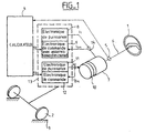
- Figure 1 shows the architecture of a restitution of effort according to the invention, driving 1 of a motor vehicle of a driving simulator, whose connection between the steering wheel and the wheels 2 resting on the floor 3 is cut off, to be used for example in an interactive driving simulator equipped with a electronic control and control computer 4.
- the device according to the invention is composed of a steering angle sensor 5, coupled to column 6 of direction of the vehicle and intended to deliver calculator 4 angular position information of the flying relative to a reference position. Beyond of the angle sensor 5, with respect to the steering wheel 1, is deposited an electric motor 7 whose output axis of the central rotor is integral with the steering column.
- This electric motor 7 is controlled by the electronic computer 4, by means of electronic means 13 for converting the target voltage, delivered by an analog output of the computer 4, into a reference current supplying the motor 7.
- the calculator has function to calculate the torque setpoint that the motor must apply to the steering column.
- the conversion means 13 comprise an electronic power circuit 8 associated with a control electronic circuit 9 with current control.
- the control computer 4 delivers a control voltage u 1 to the electronic control circuit 9, which in turn sends a current 11 to the motor via the electronic power circuit 8.
- the current i 1m flowing in the motor is measured by the sensor 14 and then returned to the conversion means 13 to be controlled by the electronic control and control computer 4 and regulated by the control electronic circuit 9.
- the current control loop is necessary to ensure a smooth operation.
- this electric motor 7 is to generate the component of the resistive torque corresponding to the return torque proportional to the transverse acceleration of the vehicle, this restoring torque being calculated by the control computer 4 as a function of vehicle parameters such as the transverse acceleration, the angle of the steering wheel, the drift, and depending on the characteristics of the vehicle such as its mass, the type of tires, the stiffness of the trains, the manual or assisted steering and its gear ratio.
- FIG. 2a is the graphical representation of the variations of the return torque C r as a function of the transverse acceleration ⁇ t corresponding to a manual direction.
- FIG. 2b is the graphical representation of the variations of the restoring torque C r as a function of the transverse acceleration ⁇ t , corresponding to a power steering having a maximum of saturation C s .
- the device In order to generate the friction torque opposing the rotation of the steering wheel, the device according to the invention also comprises (FIG. 1) a powder coupler 10, driven in current by the control computer 4, via the means of FIG. conversion 13 of a second set voltage u 2 delivered by a second analog output of the computer 4.
- These conversion means for this purpose comprise an electronic circuit 11 of power, which supplies the powder coupler 10 with a current i 2 which is depending on the voltage setpoint u 2 , delivered by the control computer 4 and received by an electronic control circuit 12.
- the current i 2m flowing in the powder coupler is returned to the electronic circuit 12 to be controlled.
- the control computer 4 supplies the powder coupler 10 with a set voltage u 2 which is proportional to the friction torque C f that the powder coupler must generate on the steering column 6.
- FIG. 3 graphically represents the component K p (V) of the friction torque which is maximum when the vehicle is at a standstill, then taking a value K p 0, called parking torque, and decreasing towards a minimum threshold value K p 1 translating the rolling hysteresis and unavoidable friction of the trains and the steering column, whatever the speed V of the vehicle.
- FIG. 4 represents the component K d ( ⁇ ') of the friction torque, which is a linear function of the steering speed ⁇ ' of the steering wheel.
- the friction torque setpoint is calculated by the control computer 4 as a function of determined parameters and characteristics of the vehicle.
- the powder coupler 10 consists of two cylinders concentric between which is enclosed a powder whose characteristics vary in function of the magnetic field that runs through it, making thus vary the coefficient of friction between two cylinders.
- the inner cylinder is attached to the steering column, while the cylinder outside is fixed, the powder between the two in front oppose the rotation of the steering column.
- the powder coupler can generate pairs of significant dry friction while being weak dimensions. Using an electric motor associated with a powder coupler, both driven by an electronic control computer, allows to carry out a device for restitution of effort relatively simple flying.
- the voltage instructions delivered by the calculator are generated at many frequencies lower, of the order of 100 Hz, which decreases the workload of the calculator, thus reducing its complexity and cost.
- the maximum torque that must provide the electric motor is significantly more low, because it corresponds only to the maximum torque the friction torque being provided by the powder coupler and whose maximum can be much higher. This achieves a gain in volume, weight and cost.
- This device has the additional advantage of being controllable in real time, the coefficient of friction created by the powder can vary, and to be numerically stable, the powder coupler creating a pure dry friction.
Landscapes
- Engineering & Computer Science (AREA)
- Theoretical Computer Science (AREA)
- Aviation & Aerospace Engineering (AREA)
- Business, Economics & Management (AREA)
- Physics & Mathematics (AREA)
- Educational Administration (AREA)
- Educational Technology (AREA)
- General Physics & Mathematics (AREA)
- Steering Control In Accordance With Driving Conditions (AREA)
- Power Steering Mechanism (AREA)
Claims (5)
- Vorrichtung zur Wiedergabe der Lenkkraft am Lenkrad eines Kraftfahrzeuges mit entkoppelter Steuerung mit einem elektronischen Befehls- und Steuerrechner (4), einem Lenkradwinkelsensor (5), einem Elektromotor (7) und einer Pulverkupplung (10), wobei die Vorrichtung weiterhin aufweist:dadurch gekennzeichnet, dasselektronische Mittel (13) zur Umwandlung der durch den Befehlsrechner (4) ausgegebenen Soll-Spannungen (u1 und u2) in Soll-Stromstärken (i1 und i2),der Lenkradwinkelsensor (5) mit der Lenksäule (6) des Fahrzeuges gekoppelt ist und mit dem Rechner (4) verbunden ist,die Ausgangswelle des Zentralrotors des Elektromotors (7) direkt einstückig mit der Lenksäule (6) verbunden ist, wobei der Motor durch einen Soll-Strom (i1) gesteuert wird, der von den Umwandlungsmitteln (13) ausgesandt wird und an die Lenksäule ein Rückführdrehmoment (Cr) anliegt, welches proportional zur Querbeschleunigung (Γt) des Fahrzeuges ist,der Innenzylinder der Pulverkupplung (10), die aus zwei konzentrischen Zylindern besteht, zwischen denen ein Magnetpulver eingeschlossen ist, direkt einstückig mit der Lenksäule (6) verbunden ist, wobei die Kupplung von einem Soll-Strom (i2) gesteuert wird, der von den Umwandlungsmitteln (13) ausgesandt wird und an die Lenksäule ein Reibungsdrehmoment (Cf) anlegt.
- Vorrichtung zur Wiedergabe der Lenkkraft gemäß Anspruch 1, dadurch gekennzeichnet, dass die Pulverkupplung (10) an die Lenksäule (6) ein Reibungsdrehmoment (Cf) anlegt, welches sich in der Form eines Produktes zwischen einerseits einer Komponente [Kp (V)], die eine Funktion der Fahrzeuggeschwindigkeit (V) ist, und andererseits einer Komponente [Kd (α')], welche eine Funktion der Geschwindigkeit (α') des Lenkrades (1) ist, ausdrückt:
- Vorrichtung zur Wiedergabe der Lenkkraft gemäß Anspruch 1, dadurch gekennzeichnet, dass die Umwandlungsmittel (13) einerseits einen elektronischen Befehlsschaltkreis (9) umfassen, der einem elektronischen Leistungsschaltkreis (8) zugeordnet ist, um den Elektromotor (7) zu versorgen, und andererseits einen elektronischen Befehlsschaltkreis (12), der einem elektronischen Leistungsschaltkreis (11) zugeordnet ist, um die Pulverkupplung (10) zu versorgen.
- Vorrichtung zur Wiedergabe der Lenkkraft gemäß Ansprüchen 1 bis 3, dadurch gekennzeichnet, dass sie zusätzlich einen Sensor (14) umfasst, der eine Regelung des den Elektromotor (7) steuernden Stromes (i1) erlaubt.
- Vorrichtung zur Wiedergabe der Lenkkraft gemäß Ansprüchen 1 bis 4, dadurch gekennzeichnet, dass die vom elektronischen Befehls- und Steuerrechner (4) gesteuerten Ströme (i1m und i2m), die jeweils im Elektromotor (7) und in der Pulverkupplung (10) verlaufen, an die Umwandlungsmittel (13) zurückgesandt werden, um sodann vom elektronischen Befehls- und Steuerrechner (4) gesteuert zu werden.
Applications Claiming Priority (2)
| Application Number | Priority Date | Filing Date | Title |
|---|---|---|---|
| FR9513353A FR2741175B1 (fr) | 1995-11-10 | 1995-11-10 | Dispositif de restitution d'effort au volant d'un vehicule automobile a direction decouplee |
| FR9513353 | 1995-11-10 |
Publications (2)
| Publication Number | Publication Date |
|---|---|
| EP0773526A1 EP0773526A1 (de) | 1997-05-14 |
| EP0773526B1 true EP0773526B1 (de) | 2005-10-26 |
Family
ID=9484452
Family Applications (1)
| Application Number | Title | Priority Date | Filing Date |
|---|---|---|---|
| EP19960402381 Expired - Lifetime EP0773526B1 (de) | 1995-11-10 | 1996-11-08 | Vorrichtung zum Erzeugen einer Lenkkraftreaktion am Lenkrad eines Karftfahrzeuges mit entkoppelter Steuerung |
Country Status (2)
| Country | Link |
|---|---|
| EP (1) | EP0773526B1 (de) |
| FR (1) | FR2741175B1 (de) |
Families Citing this family (4)
| Publication number | Priority date | Publication date | Assignee | Title |
|---|---|---|---|---|
| ES2144965B1 (es) * | 1998-08-12 | 2001-01-01 | Univ Valencia Politecnica | Simulador de conduccion de automoviles, para la evaluacion de conductores discapacitados. |
| FR2802491B1 (fr) * | 1999-12-17 | 2002-02-01 | Renault | Systeme de direction de vehicule sans colonne de direction avec restitution d'efforts au conducteur |
| FR2809522B1 (fr) * | 2000-05-29 | 2004-10-01 | Renault | Simulateur de conduite de vehicule automobile |
| KR101429404B1 (ko) * | 2013-07-18 | 2014-08-13 | 재단법인대구경북과학기술원 | 운전 시뮬레이터 장치 및 이를 이용한 운전 재활 훈련 방법 |
Family Cites Families (4)
| Publication number | Priority date | Publication date | Assignee | Title |
|---|---|---|---|---|
| US5044956A (en) | 1989-01-12 | 1991-09-03 | Atari Games Corporation | Control device such as a steering wheel for video vehicle simulator with realistic feedback forces |
| FR2678884B1 (fr) * | 1991-07-12 | 1996-08-14 | Sextant Avionique | Actionneur rotatif apte a engendrer sur le volant de manóoeuvre d'un systeme de commande, un couple resistant variable selon une loi adaptative. |
| JPH07234628A (ja) * | 1994-02-21 | 1995-09-05 | Sega Enterp Ltd | 模擬ステアリング装置 |
| JP2665313B2 (ja) * | 1994-04-22 | 1997-10-22 | 国際電業株式会社 | 反力発生装置 |
-
1995
- 1995-11-10 FR FR9513353A patent/FR2741175B1/fr not_active Expired - Fee Related
-
1996
- 1996-11-08 EP EP19960402381 patent/EP0773526B1/de not_active Expired - Lifetime
Also Published As
| Publication number | Publication date |
|---|---|
| FR2741175B1 (fr) | 1997-12-12 |
| EP0773526A1 (de) | 1997-05-14 |
| FR2741175A1 (fr) | 1997-05-16 |
Similar Documents
| Publication | Publication Date | Title |
|---|---|---|
| EP3065987B1 (de) | Verfahren und system zum steuern des regenerativen bremsen von einem elektrischen oder einem hybrid fahrzeug | |
| EP2018308B1 (de) | Elektrisches servolenksystem für ein kraftfahrzeug | |
| US6416441B1 (en) | process and a device for determining the driving torque of a vehicle | |
| GB2316191A (en) | Controlling the longitudinal dynamics of a motor vehicle | |
| EP3727970B1 (de) | Verfahren zur bestimmung des motor-sollmoments eines kraftfahrzeugs | |
| FR2756784A1 (fr) | Controleur de commande pour vehicule electrique | |
| EP3860901B1 (de) | Kraftfahrzeugparkhilfeverfahren und system | |
| FR2695613A1 (fr) | Procédé et dispositif de correction automatique d'un mouvement de lacet d'un véhicule routier. | |
| EP0773526A1 (de) | Vorrichtung zum Erzeugen einer Lenkkraftreaktion am Lenkrad eines Karftfahrzeuges mit entkoppelter Steuerung | |
| EP3850203A1 (de) | Verfahren zur steuerung des motordrehmoments einer antriebseinheit mit ermöglichung der deaktivierung der kompensierung des massenträgheitsmoments | |
| EP1791745B1 (de) | Verfahren zur erzeugung eines an eine neigungs- und/oder ladesituation angepassten steuersollwertes für eine fahrzeugmotor-getriebeeinheit, getriebevorrichtung und entsprechende vorrichtung | |
| FR2678884A1 (fr) | Actionneur rotatif apte a engendrer sur le volant de manóoeuvre d'un systeme de commande, un couple resistant variable selon une loi adaptative. | |
| FR2491660A1 (fr) | Simulateur de conduite de vehicule automobile | |
| WO2005119033A2 (fr) | Procede de controle d'une consigne de couple a appliquer aux roues d'une transmission automatisee pour vehicule automobile et dispositif correspondant. | |
| FR2749248A1 (fr) | Procede et dispositif pour determiner les forces d'attelage dans un train routier | |
| FR2976887A3 (fr) | Systeme embarque de controle de vitesse d'un vehicule et procede de fonctionnement | |
| FR2791026A1 (fr) | Procede et systeme de compensation de la variation de rappel volant et de l'amortissement de la vitesse volant | |
| EP1661793A2 (de) | System und Verfahren zur Ansteueren des Lenkwinkels von gelenkten Kraftfahrzeugrädern | |
| FR2927601A3 (fr) | Procede de fonctionnement d'un systeme de direction a commande electrique d'un vehicule automobile et systeme de direction a commande electrique associe | |
| FR2942440A1 (fr) | Procede de controle du comportement dynamique d'un vehicule automobile. | |
| FR2936061A3 (fr) | Dispositif et procede de calcul de la vitesse longitudinale d'un vehicule. | |
| EP1846647A1 (de) | Verfahren zur steuerung der leistungsumkehr in einem system mit einem drehmomentwandler und das verfahren umfassende mechanische einheit | |
| EP2495154A1 (de) | "Lenksystem vom Typ ""Steer-by-wire"" für Kraftfahrzeug " | |
| FR2795377A1 (fr) | Systeme de pilotage de l'actionneur de direction d'un vehicule automobile | |
| FR2919255A1 (fr) | Dispositif de direction pour vehicule, procede et vehicule correspondant. |
Legal Events
| Date | Code | Title | Description |
|---|---|---|---|
| PUAI | Public reference made under article 153(3) epc to a published international application that has entered the european phase |
Free format text: ORIGINAL CODE: 0009012 |
|
| AK | Designated contracting states |
Kind code of ref document: A1 Designated state(s): BE ES GB IT SE |
|
| 17P | Request for examination filed |
Effective date: 19971023 |
|
| RAP1 | Party data changed (applicant data changed or rights of an application transferred) |
Owner name: RENAULT S.A.S. |
|
| 17Q | First examination report despatched |
Effective date: 20040608 |
|
| GRAP | Despatch of communication of intention to grant a patent |
Free format text: ORIGINAL CODE: EPIDOSNIGR1 |
|
| GRAS | Grant fee paid |
Free format text: ORIGINAL CODE: EPIDOSNIGR3 |
|
| GRAA | (expected) grant |
Free format text: ORIGINAL CODE: 0009210 |
|
| AK | Designated contracting states |
Kind code of ref document: B1 Designated state(s): BE ES GB IT SE |
|
| PG25 | Lapsed in a contracting state [announced via postgrant information from national office to epo] |
Ref country code: IT Free format text: LAPSE BECAUSE OF FAILURE TO SUBMIT A TRANSLATION OF THE DESCRIPTION OR TO PAY THE FEE WITHIN THE PRE;WARNING: LAPSES OF ITALIAN PATENTS WITH EFFECTIVE DATE BEFORE 2007 MAY HAVE OCCURRED AT ANY TIME BEFORE 2007. THE CORRECT EFFECTIVE DATE MAY BE DIFFERENT FROM THE ONE RECORDED.SCRIBED TIME-LIMIT Effective date: 20051026 |
|
| REG | Reference to a national code |
Ref country code: GB Ref legal event code: FG4D Free format text: NOT ENGLISH |
|
| GBT | Gb: translation of ep patent filed (gb section 77(6)(a)/1977) |
Effective date: 20051026 |
|
| PG25 | Lapsed in a contracting state [announced via postgrant information from national office to epo] |
Ref country code: SE Free format text: LAPSE BECAUSE OF FAILURE TO SUBMIT A TRANSLATION OF THE DESCRIPTION OR TO PAY THE FEE WITHIN THE PRESCRIBED TIME-LIMIT Effective date: 20060126 |
|
| PG25 | Lapsed in a contracting state [announced via postgrant information from national office to epo] |
Ref country code: ES Free format text: LAPSE BECAUSE OF FAILURE TO SUBMIT A TRANSLATION OF THE DESCRIPTION OR TO PAY THE FEE WITHIN THE PRESCRIBED TIME-LIMIT Effective date: 20060206 |
|
| PLBE | No opposition filed within time limit |
Free format text: ORIGINAL CODE: 0009261 |
|
| STAA | Information on the status of an ep patent application or granted ep patent |
Free format text: STATUS: NO OPPOSITION FILED WITHIN TIME LIMIT |
|
| 26N | No opposition filed |
Effective date: 20060727 |
|
| PGFP | Annual fee paid to national office [announced via postgrant information from national office to epo] |
Ref country code: GB Payment date: 20101118 Year of fee payment: 15 |
|
| PGFP | Annual fee paid to national office [announced via postgrant information from national office to epo] |
Ref country code: BE Payment date: 20111110 Year of fee payment: 16 |
|
| BERE | Be: lapsed |
Owner name: *RENAULT S.A.S. Effective date: 20121130 |
|
| GBPC | Gb: european patent ceased through non-payment of renewal fee |
Effective date: 20121108 |
|
| PG25 | Lapsed in a contracting state [announced via postgrant information from national office to epo] |
Ref country code: BE Free format text: LAPSE BECAUSE OF NON-PAYMENT OF DUE FEES Effective date: 20121130 |
|
| PG25 | Lapsed in a contracting state [announced via postgrant information from national office to epo] |
Ref country code: GB Free format text: LAPSE BECAUSE OF NON-PAYMENT OF DUE FEES Effective date: 20121108 |