EP0773392A1 - Abdichtung - Google Patents
Abdichtung Download PDFInfo
- Publication number
- EP0773392A1 EP0773392A1 EP96307823A EP96307823A EP0773392A1 EP 0773392 A1 EP0773392 A1 EP 0773392A1 EP 96307823 A EP96307823 A EP 96307823A EP 96307823 A EP96307823 A EP 96307823A EP 0773392 A1 EP0773392 A1 EP 0773392A1
- Authority
- EP
- European Patent Office
- Prior art keywords
- seal according
- embossment
- seal
- support
- embossments
- Prior art date
- Legal status (The legal status is an assumption and is not a legal conclusion. Google has not performed a legal analysis and makes no representation as to the accuracy of the status listed.)
- Granted
Links
Images


Classifications
-
- F—MECHANICAL ENGINEERING; LIGHTING; HEATING; WEAPONS; BLASTING
- F16—ENGINEERING ELEMENTS AND UNITS; GENERAL MEASURES FOR PRODUCING AND MAINTAINING EFFECTIVE FUNCTIONING OF MACHINES OR INSTALLATIONS; THERMAL INSULATION IN GENERAL
- F16J—PISTONS; CYLINDERS; SEALINGS
- F16J15/00—Sealings
- F16J15/02—Sealings between relatively-stationary surfaces
- F16J15/06—Sealings between relatively-stationary surfaces with solid packing compressed between sealing surfaces
- F16J15/10—Sealings between relatively-stationary surfaces with solid packing compressed between sealing surfaces with non-metallic packing
- F16J15/12—Sealings between relatively-stationary surfaces with solid packing compressed between sealing surfaces with non-metallic packing with metal reinforcement or covering
- F16J15/121—Sealings between relatively-stationary surfaces with solid packing compressed between sealing surfaces with non-metallic packing with metal reinforcement or covering with metal reinforcement
- F16J15/122—Sealings between relatively-stationary surfaces with solid packing compressed between sealing surfaces with non-metallic packing with metal reinforcement or covering with metal reinforcement generally parallel to the surfaces
- F16J15/123—Details relating to the edges of the packing
-
- F—MECHANICAL ENGINEERING; LIGHTING; HEATING; WEAPONS; BLASTING
- F16—ENGINEERING ELEMENTS AND UNITS; GENERAL MEASURES FOR PRODUCING AND MAINTAINING EFFECTIVE FUNCTIONING OF MACHINES OR INSTALLATIONS; THERMAL INSULATION IN GENERAL
- F16J—PISTONS; CYLINDERS; SEALINGS
- F16J15/00—Sealings
- F16J15/02—Sealings between relatively-stationary surfaces
- F16J15/06—Sealings between relatively-stationary surfaces with solid packing compressed between sealing surfaces
- F16J15/08—Sealings between relatively-stationary surfaces with solid packing compressed between sealing surfaces with exclusively metal packing
- F16J15/0818—Flat gaskets
- F16J15/0825—Flat gaskets laminated
-
- F—MECHANICAL ENGINEERING; LIGHTING; HEATING; WEAPONS; BLASTING
- F16—ENGINEERING ELEMENTS AND UNITS; GENERAL MEASURES FOR PRODUCING AND MAINTAINING EFFECTIVE FUNCTIONING OF MACHINES OR INSTALLATIONS; THERMAL INSULATION IN GENERAL
- F16J—PISTONS; CYLINDERS; SEALINGS
- F16J15/00—Sealings
- F16J15/02—Sealings between relatively-stationary surfaces
- F16J15/06—Sealings between relatively-stationary surfaces with solid packing compressed between sealing surfaces
- F16J15/08—Sealings between relatively-stationary surfaces with solid packing compressed between sealing surfaces with exclusively metal packing
- F16J15/0818—Flat gaskets
- F16J2015/0837—Flat gaskets with an edge portion folded over a second plate or shim
-
- F—MECHANICAL ENGINEERING; LIGHTING; HEATING; WEAPONS; BLASTING
- F16—ENGINEERING ELEMENTS AND UNITS; GENERAL MEASURES FOR PRODUCING AND MAINTAINING EFFECTIVE FUNCTIONING OF MACHINES OR INSTALLATIONS; THERMAL INSULATION IN GENERAL
- F16J—PISTONS; CYLINDERS; SEALINGS
- F16J15/00—Sealings
- F16J15/02—Sealings between relatively-stationary surfaces
- F16J15/06—Sealings between relatively-stationary surfaces with solid packing compressed between sealing surfaces
- F16J15/08—Sealings between relatively-stationary surfaces with solid packing compressed between sealing surfaces with exclusively metal packing
- F16J15/0818—Flat gaskets
- F16J2015/085—Flat gaskets without fold over
-
- F—MECHANICAL ENGINEERING; LIGHTING; HEATING; WEAPONS; BLASTING
- F16—ENGINEERING ELEMENTS AND UNITS; GENERAL MEASURES FOR PRODUCING AND MAINTAINING EFFECTIVE FUNCTIONING OF MACHINES OR INSTALLATIONS; THERMAL INSULATION IN GENERAL
- F16J—PISTONS; CYLINDERS; SEALINGS
- F16J15/00—Sealings
- F16J15/02—Sealings between relatively-stationary surfaces
- F16J15/06—Sealings between relatively-stationary surfaces with solid packing compressed between sealing surfaces
- F16J15/08—Sealings between relatively-stationary surfaces with solid packing compressed between sealing surfaces with exclusively metal packing
- F16J15/0818—Flat gaskets
- F16J2015/0856—Flat gaskets with a non-metallic coating or strip
-
- F—MECHANICAL ENGINEERING; LIGHTING; HEATING; WEAPONS; BLASTING
- F16—ENGINEERING ELEMENTS AND UNITS; GENERAL MEASURES FOR PRODUCING AND MAINTAINING EFFECTIVE FUNCTIONING OF MACHINES OR INSTALLATIONS; THERMAL INSULATION IN GENERAL
- F16J—PISTONS; CYLINDERS; SEALINGS
- F16J15/00—Sealings
- F16J15/02—Sealings between relatively-stationary surfaces
- F16J15/06—Sealings between relatively-stationary surfaces with solid packing compressed between sealing surfaces
- F16J15/08—Sealings between relatively-stationary surfaces with solid packing compressed between sealing surfaces with exclusively metal packing
- F16J15/0818—Flat gaskets
- F16J2015/0862—Flat gaskets with a bore ring
Definitions
- the present invention relates to a seal. More particularly, the invention relates to a seal for sealing between two generally parallel surfaces; for example, such as for establishing a leak-proof seal between the cylinder head and cylinder block of a petrol or diesel engine. Further applications include the sealing of gases between inlet/exhaust manifolds and applications in pumps and valves.
- the present invention sets out to overcome the above-mentioned problems whilst ensuring that the seal is relatively easy to handle and install.
- the invention sets out to provide a highly flexible seal which can cope with the differential expansions between, for example, the cylinder head and manifold of an engine.
- the invention sets out to provide a seal which has a good recovery factor, and which will not result in galling or other damage to sealing surfaces.
- a seal for sealing between two opposed and generally parallel surfaces comprising support means for location between the said opposed surfaces and a pair of opposed sealing layers supported by the support means and projecting beyond an edge of the support means for effecting a seal between the said opposed surfaces when the said seal is located therebetween.
- the support means provides the requisite stiffness, so as to facilitate handling and installation.
- the sealing layers are able to move independently of the support means during compression and can therefore roll to effect a seal.
- the result is a highly flexible seal that is well able to cope with differential expansions between sealed surfaces, requires only modest clamping loads, and has built-in compression control.
- the seal can also be self-energising.
- sealing By enabling a rolling (rather than crushing) deformation of the sealing surfaces, sealing can be achieved without galling occurring. Furthermore, the recovery factor is good, and the sealing surfaces are not damaged.
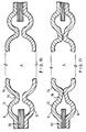
- Figure 1 shows a gasket (seal) 2 comprising a circular central aperture 4.
- the gasket 2 is situated between opposed parallel surfaces, to prevent leakage from respective passages which are located on either side and communicate via the aperture 4.
- Figure 2 shows a cross-section along the line A-A of Figure 1.
- the seal structure is formed from three layers.
- Outer (sealing) layers 6, 8 are embossed and have sectional profiles which are mirror images of each other in the region of the aperture 4.
- Each of these outer layers comprises two annular embossments 12, 14, which are each arcuate in cross-section with the same radius of curvature and arranged concentrically .
- the radially inner and outer embossments are separated by a respective intermediate flat land 16.
- the flat lands 16 are in close contact with each other and are firmly pressed together during assembly.
- the radially outer embossments 12 are configured such that they, together, generally define an "O"-shaped portion.
- the radially inner (distal) embossments are truncated, so as to, together, define a generally "C"-shaped portion.
- each of the distal embossments 14 has an arc of 120°.
- the radially outer embossments 12 lead into flat portions 18, which are parallel to the radial plane.
- the embossments each extend through an arc which is less than 180° from the lands 16. This provides a space between the flat portions 18. This space accommodates the third (intermediate) layer 10.
- the intermediate layer 10 is substantially thicker than each of the layers 6 and 8. This enables it to provide strength and stiffness to the seal structure, by acting as a support plate.
- the radially inner edge 20 of the intermediate plate 10 is located on the centre line of the radially outer embossments 12.
- the intermediate plate 10 has a thickness of 0.38 mm and each of the outer layers 6, 8 has a thickness of 0.25 mm.
- the aperture has a diameter of 46 mm.
- Figure 3 shows the loading (P) on the seal just before compression starts.
- Figure 4 shows the seal under compression.
- the arrows in Figure 4 illustrate the high pressure sealing points of the seal. Comparison of these figures will immediately show that, under compression, the shape of the seal changes considerably. This change in form is a consequence of the various hoop strengths existent in the seal reacting to one another.
- the radially inner end 20 of the plate 10 extends to the centre line of the "O"-portion. Although it is not crucial that the end portion extends this far, it is highly preferable that it extends beyond the junction of the radially outer ends of the arcuate portions 6 and the flat regions 18. If the middle layer 10 did not do this, it is possible that metal fatigue could cause cracking as a result of fretting occurring on the sharp corner in some applications .
- Figure 5 shows a second embodiment. This has a generally similar construction to the embodiment of Figures 2 to 4, but the intermediate plate 10 is replaced by a pair of outer plates 10a and 10b, which serve essentially the same function. To accommodate this, the flat portions 18 are now in direct contact and the radially outer embossments 12 consequently extend through a greater arc of 180°.
- Figure 6 shows a third embodiment, which has a generally similar configuration to the first embodiment.
- the intermediate plate 10 is slightly thinner, the lands 16 are separated by a gap in the uncompressed state and the distal embossments 14 are more flared. In this regard, they extend through an arc of only 90° in the uncompressed state, but extend further in the axial direction than those of the first embodiment. This is achieved by virtue of the fact that they have a greater radius of curvature than those of the previous embodiments.
- This seal is intended for use in arrangements where the opposition of the sealing surfaces is very weak - either due to relative thinness of the flanges upon which the sealing surfaces are located, or bolts securing the sealing surfaces together having a small diameter. In such a case, a much lighter clamping load is demanded.
- the mating surfaces would in this case include a high quality of finish - in order to compensate for the lighter clamping load.
- Figure 7 illustrates a fourth embodiment of the invention.
- This embodiment is generally similar to the embodiment of Figure 6, but the distal embossments 14 are extended radially inwardly, so as to accommodate a fire ring 22.
- the fire ring can be used to prevent the thin metal of the seal becoming incandescent - thereby resisting pre-ignition and improper combustion.
- Figure 8 shows a fifth embodiment of the present invention.
- the intermediate layer 10 has a different configuration from the previous embodiments. It comprises a relatively thick radially outer portion 24 and a relatively thin radially inner portion 26.
- the radially outer portion 24 corresponds in function to the original intermediate layer 10 shown in the previous embodiments. In this regard, it will be noted that it extends to the centre line of the radially outer embossments 12.
- the thickness of this part is greater than in previous embodiments, to enable the gasket to meet demands for variations in engine compression ratio. This might be required, for example, in order to cope with variations in fuel quality - which vary greatly around the world.
- Figure 10 shows a further embodiment having general similarity to the embodiment of Figure 6.
- the middle layer 10 is slightly thicker than the embodiment of Figure 6 and the distal embossments 14 extend through a slightly greater angle.
- Figure 11 shows a still further embodiment of the invention in which the lands 16 meet at their radially innermost edge and diverge in the radially outward direction. It will be noted that the lands 16 are somewhat wider in this case and that the radius of curvature of the distal embossments 14 is somewhat smaller than in previous embodiments.
- Figures 12 to 15 show a still further embodiment of the present invention in which a pair of sealing regions are coupled together in a single gasket. It has been found that in certain circumstances the available space for embossment formation is restricted. This embodiment addresses this particular problem in addition to the others mentioned above.
- FIG. 14 and 15 will show that the outer layers 6 and 8 in this case each comprise only a single embossment 12. Furthermore, these embossments are not mirror images of each other when viewed in cross-section.
- the first sealing layer 6 (the upper layer in Figure 14) has a smaller radius of curvature than the second sealing layer 8 (the lower layer in Figure 14).
- the embossments 12 overlap in their radially innermost regions.
- the outer diameter of the embossment 12 of the upper sealing layer 6 is slightly smaller than the inner diameter of the embossments 12 of the lower sealing layer 8.
- the embossment 12 of the lower sealing layer 8 extends as a circular arc from where it joins its respective flat portion 18 until the central radial plane of the seal. From here it follows a generally straight path until its distal end 26 .
- the embossment 12 of the upper sealing layer 6 follows a circular cross-sectional profile from its junction with the flat layer 18 until it has extended 15° past its point of first contact with the radially inner surface of the embossment 12 of the lower sealing layer 8.
- the radially inner end of the intermediate plate 10 extends as far as the centre line of the embossment 12 of the upper sealing layer 6.
- the embossment 12 of the upper sealing layer 6 Upon loading, the embossment 12 of the upper sealing layer 6 is forced to roll inside the embossment 12 of the lower sealing layer 8. This causes the embossment 12 of the upper sealing layer 6 to curl back upon itself, as shown in Figure 15.
- the embossment 12 of the lower sealing layer 8 is also bent and somewhat flattened-out in the proximity of the lower sealing surface. However, it will be noticed that its distal region remains axially orientated. This maintains the strength of the seal.
- the distal end 26 of this embossment 12 may be configured for location in close proximity to the upper sealing surface of Figure 15. In such a case, the distal end 26 may effect a jacking force.
- the seal behaves in this way because, when compression is applied, the support plate 10 causes a rolling effect to take place in the two radially outer quadrants of the embossments 12 along both sides of the support plate. During this process, the flat portions 18 of the sealing plates 6, 8, being very strong, resist the compression of the embossments 12. Similar resistance occurs in the two radially inner quadrants. This resistance to compression is further enhanced by the inner curl of the quadrants and the natural built-in hoop strength of the seal.
- the sealing layer 6 may, in practice, be thinner than the sealing layer 8 to assist it to roll within the curvature of the embossment of the sealing layer 8.
- the sealing layer 6 may be made from the material that is more flexible than that of the sealing layer 8.
- thermal expansion/contraction slots 40 are provided between each sealing region. These allow the seal to contract in the left-right direction of the figure. This is facilitated by the layered structure of the seal, which enables the sealing layers 6, 8 to be omitted in the central region. A further consequence of this structure, is that bowing, due to movement between the sealing surfaces is avoided. Slots such as those shown in this embodiment can be used with any of the sealing structures employed in any of the other embodiments.
- Figures 16 and 17 show a further embodiment of the invention, which is a variation of the embodiment shown in Figure 5.
- the embodiment of Figure 5 provides a highly effective seal. Where operating conditions are not so demanding, the three-piece seal of Figure 2 can be used very satisfactorily and has the advantage of saving as much as 25% in material requirements. However, it is obviously highly desirable to reduce manufacturing costs as much as possible. Due to its two-piece construction, the embodiment of Figure 16 and 17 satisfies this desire most effectively.
- the embodiment of Figures 16 and 17 functions on a similar basis to the embodiment of Figure 5.
- the plates 10a and 10b of Figure 5 are omitted.
- the-layers 6 and 8 are each provided with a pair of embossments 110a, 110c and 110b, 110d, respectively.
- the embossments provided in each plate are mirror images of those provided in the other.
- each layer 6, 8 is provided with an embossment 110c, 110d which has a generally rectangular cross-sectional profile.
- embossments 110c, 110d therefore, include a series of walls 111 which are perpendicular to the opposed faces between which the seal operates. These perpendicular walls operate as struts of very great strength and can thereby control the degree of compression of the seal with high accuracy. The result is that over-compression of the seal can be avoided.
- V-shaped or arcuate embossments could be used instead of the rectangular embossments, but these will not provide the same degree of strength. However, because such embossments can be easier to manufacture, it may be desirable to use them where the seal is likely to experience lower compressive loads.
- Each layer 6, 8 of the seal also comprises a buttress corrugation 110a, 110b which has a saw-tooth profile in cross-section.
- These corrugations 110a, 110b therefore, each define a wall 112, which is perpendicular to the loading faces. Due to their location between the aperture 4 and the rectangular embossments, these corrugations prevent the ballooning (i.e. separating) of the layers 6, 8. This ensures a good sealing effect. If the layers 6 and 8 bowed away from each other in this region, this would cause the distal embossments 14 to tilt towards each other and, thus, away from the opposed faces. This would reduce the sealing effect that the seal could provide between the opposed faces.
- the buttress corrugations 110a, 110b have a saw-tooth profile, because this provides one perpendicular wall 112 in combination with economical manufacture.
- a perpendicular wall provides a particularly strong resistance to movement.
- Corrugations having other profiles such as V-shaped or arcuate could be used instead.
- the position of the embossments can be varied. In certain applications, the strategic positioning of these embossments can lead to a performance that exceeds that of the embodiment of Figure 5. Indeed, it will be noted from Figure 16 that the buttress embossments 110a, 110b do not extend around the whole of the aperture. Instead, they are located merely where bowing between the layers 6, 8 is most likely to occur. This has the advantage of an even further saving in raw material.
- embossments 110a, 110c, 110b, 110d Whilst two embossments 110a, 110c, 110b, 110d are provided in each layer in this embodiment, it may be desirable to eliminate one or the other of the embossments if either is deemed unnecessary or there is insufficient space to provide both.
- the arrangement of embossments will depend upon the particular application and particularly, the likelihood of ballooning or over-compression across the seal.
- shims may be inserted inside the embossments, in order to carry the excessively high compression loads.
- all layers may be made from stainless steel.
- the sealing layers may be made from stainless steel with the support plate or plates (where such are provided) being manufactured from carbon steel.
- Stainless steel sealing layers provide good temperature resistance and good spring qualities.
- the seals may have their sealing qualities improved by soft metal, Viton (trade mark) or Nitrile (trade mark) rubber coatings.
- Viton trade mark
- Nitrile trademark
- both surfaces of the middle layer 10 and the outer surfaces of the outer layers 6, 8 could be coated with Viton (trade mark) and/or Nitrile (trade mark).
- Nimonics trade. mark
- Inconels trade mark
- the reliefed section of the seal may be capable of compression down to a thickness equal to that of the composite layers of metal when flat.
- a shim of pre-determined thickness in strategic positions, such as for example, in bolting regions, compression can be controlled. This can greatly enhance the reflex quality of the seals, particularly in situations where a designer cannot obtain the most desirable gasket bolting patterns.
- a wire or PTFE ring can be inserted between the distal embossments in order to prevent food becoming trapped within the seal.
- seals and gaskets for use in a wide variety of applications. These will include, inter alia, single and multi-aperture gaskets and seals for sealing apertures having other than circular shapes including those having irregular shapes.
Applications Claiming Priority (4)
| Application Number | Priority Date | Filing Date | Title |
|---|---|---|---|
| GBGB9522785.6A GB9522785D0 (en) | 1995-11-07 | 1995-11-07 | Seal |
| GB9522785 | 1995-11-07 | ||
| GB9620754 | 1996-10-04 | ||
| GB9620754A GB2307014B (en) | 1995-11-07 | 1996-10-04 | Seal |
Publications (2)
| Publication Number | Publication Date |
|---|---|
| EP0773392A1 true EP0773392A1 (de) | 1997-05-14 |
| EP0773392B1 EP0773392B1 (de) | 2004-12-15 |
Family
ID=26308067
Family Applications (1)
| Application Number | Title | Priority Date | Filing Date |
|---|---|---|---|
| EP96307823A Expired - Lifetime EP0773392B1 (de) | 1995-11-07 | 1996-10-29 | Abdichtung |
Country Status (5)
| Country | Link |
|---|---|
| US (1) | US6131915A (de) |
| EP (1) | EP0773392B1 (de) |
| JP (1) | JPH09229197A (de) |
| CA (1) | CA2189704A1 (de) |
| DE (1) | DE69634031D1 (de) |
Cited By (10)
| Publication number | Priority date | Publication date | Assignee | Title |
|---|---|---|---|---|
| WO1998009100A1 (en) * | 1996-08-29 | 1998-03-05 | Flexitallic Investments, Inc. | Gasket |
| WO1998009102A1 (en) * | 1996-08-29 | 1998-03-05 | Flexitallic Limited | Gaskets |
| EP0893631A3 (de) * | 1997-07-22 | 1999-07-21 | Reinz-Dichtungs-Gmbh | Metallische Flachdichtung |
| EP0893630A3 (de) * | 1997-07-22 | 1999-08-04 | Reinz-Dichtungs-Gmbh | Metallische Flachdichtung |
| EP0987474A3 (de) * | 1998-09-18 | 2000-10-25 | Taiho Kogyo Co., Ltd. | Zylinderkopfdichtung |
| DE19731492C2 (de) * | 1997-07-22 | 2001-07-19 | Reinz Dichtungs Gmbh | Metallische Flachdichtung |
| WO2005085685A1 (en) * | 2004-02-28 | 2005-09-15 | Swagelok Company | Seal assembly for fluid components |
| EP1637780A1 (de) * | 2004-09-21 | 2006-03-22 | Carl Freudenberg KG | Dichtung mit mindestens einem Wulst mit integriertem Begrenzer |
| WO2010072402A1 (en) | 2008-12-23 | 2010-07-01 | Reinz-Dichtungs-Gmbh | Hydraulic control plate |
| AT522742A1 (de) * | 2019-06-28 | 2021-01-15 | Avl List Gmbh | Zylinderkopfdichtung |
Families Citing this family (21)
| Publication number | Priority date | Publication date | Assignee | Title |
|---|---|---|---|---|
| FR2824613B1 (fr) * | 2001-05-09 | 2003-07-25 | Meillor Sa | Joint metallique a insert fibreux |
| JP2004060842A (ja) * | 2002-07-31 | 2004-02-26 | Nichias Corp | ガスケット |
| US7234705B2 (en) * | 2003-08-28 | 2007-06-26 | Freudenberg-Nok General Partnership | Sealing gasket with flexible stopper |
| CA2477342A1 (en) * | 2003-08-28 | 2005-02-28 | Freudenberg-Nok General Partnership | Improved sealing gasket with flexible stopper |
| US20070262534A1 (en) * | 2004-08-12 | 2007-11-15 | Ryan Hunter | Head gasket for internal combustion engines |
| US7287757B2 (en) * | 2005-06-28 | 2007-10-30 | Dana Corporation | Optimized wave bead with full bead design |
| US7726662B2 (en) * | 2006-07-10 | 2010-06-01 | Dana Automotive Systems Group, Llc | Stopped-active type cylinder head gasket |
| JP4361096B2 (ja) * | 2007-01-05 | 2009-11-11 | 石川ガスケット株式会社 | 金属製ガスケット |
| JP2008248952A (ja) * | 2007-03-29 | 2008-10-16 | Nichias Corp | 金属ガスケット |
| JP4534097B2 (ja) * | 2007-09-12 | 2010-09-01 | 日本ガスケット株式会社 | シリンダヘッドガスケット |
| JP2009243540A (ja) * | 2008-03-29 | 2009-10-22 | Daihatsu Motor Co Ltd | メタルガスケット |
| JP5212667B2 (ja) * | 2008-09-18 | 2013-06-19 | 日本ガスケット株式会社 | シリンダヘッドガスケット |
| DE102009020490B4 (de) * | 2009-05-08 | 2012-07-12 | Federal-Mogul Sealing Systems Gmbh | Dichtungselement zur Abdichtung von Flanschflächen bei Brennkraftmaschinen |
| EP2467627B1 (de) * | 2009-08-19 | 2016-05-11 | Federal-Mogul Corporation | Zylinderkopfdichtungsanordnung |
| US9429102B2 (en) * | 2011-12-01 | 2016-08-30 | Borgwarner Inc. | Metal bead gasket |
| JP6037543B2 (ja) * | 2012-05-23 | 2016-12-07 | 内山工業株式会社 | ガスケット |
| US9657840B2 (en) * | 2014-08-19 | 2017-05-23 | Federal-Mogul Llc | Multi-layer gasket assembly |
| US20150069718A1 (en) * | 2013-09-12 | 2015-03-12 | Federal-Mogul Corporation | Metal gasket assembly |
| US9528466B2 (en) * | 2015-02-27 | 2016-12-27 | Federal-Mogul Corporation | Cylinder head gasket |
| DE102017122233A1 (de) * | 2017-08-25 | 2019-02-28 | Elringklinger Ag | Metallische Dichtungsanordnung und und Verfahren zur Herstellung |
| DE102020133200A1 (de) * | 2020-12-11 | 2022-06-15 | Schwäbische Hüttenwerke Automotive GmbH | Sickendichtung |
Citations (3)
| Publication number | Priority date | Publication date | Assignee | Title |
|---|---|---|---|---|
| EP0492809A1 (de) * | 1990-12-13 | 1992-07-01 | Ishikawa Gasket Co. Ltd. | Dichtung aus Schichtstahl |
| WO1992012365A1 (en) * | 1990-12-31 | 1992-07-23 | Specialist Sealing Limited | Seal |
| US5551709A (en) * | 1995-04-07 | 1996-09-03 | Dana Corporation | Multiple layer cylinder head gasket with a wire ring |
Family Cites Families (13)
| Publication number | Priority date | Publication date | Assignee | Title |
|---|---|---|---|---|
| GB1260236A (en) * | 1969-06-23 | 1972-01-12 | Engineering Components Ltd | Improvements in or relating to gaskets, particularly for internal combustion engines |
| GB8332855D0 (en) * | 1983-12-08 | 1984-01-18 | Payen Int Ltd | Gaskets |
| US4861046A (en) * | 1988-05-16 | 1989-08-29 | Ishikawa Gasket Co., Ltd. | Steel laminate gasket with separate beads |
| US4898396A (en) * | 1988-08-11 | 1990-02-06 | Ishikawa Gasket Co., Ltd. | Steel laminate gasket |
| WO1990007663A1 (en) * | 1988-12-23 | 1990-07-12 | Specialist Sealing Limited | Cylinder head gasket - |
| US4976445A (en) * | 1989-07-05 | 1990-12-11 | Ishikawa Gasket Co., Ltd. | Steel laminate gasket |
| US5560623A (en) * | 1990-04-04 | 1996-10-01 | Kabushiki Kaisha Ket And Ket | Metal gasket |
| JPH05340476A (ja) * | 1992-06-09 | 1993-12-21 | Japan Metal Gasket Co Ltd | 金属ガスケット |
| DE4219709C2 (de) * | 1992-06-16 | 2001-07-12 | Reinz Dichtungs Gmbh | Metallische Flachdichtung |
| JP3197395B2 (ja) * | 1993-01-14 | 2001-08-13 | 日本メタルガスケット株式会社 | 金属ガスケット |
| JP3581162B2 (ja) * | 1993-07-07 | 2004-10-27 | 日本リークレス工業株式会社 | 金属ガスケットの製造方法 |
| JPH07253162A (ja) * | 1994-06-30 | 1995-10-03 | Nippon Riikuresu Kogyo Kk | メタルガスケット |
| DE9414941U1 (de) * | 1994-09-14 | 1994-11-10 | Reinz Dichtungs Gmbh | Metallische Flachdichtung |
-
1996
- 1996-10-29 DE DE69634031T patent/DE69634031D1/de not_active Expired - Lifetime
- 1996-10-29 EP EP96307823A patent/EP0773392B1/de not_active Expired - Lifetime
- 1996-11-01 US US08/742,851 patent/US6131915A/en not_active Expired - Lifetime
- 1996-11-06 CA CA002189704A patent/CA2189704A1/en not_active Withdrawn
- 1996-11-07 JP JP8295506A patent/JPH09229197A/ja active Pending
Patent Citations (3)
| Publication number | Priority date | Publication date | Assignee | Title |
|---|---|---|---|---|
| EP0492809A1 (de) * | 1990-12-13 | 1992-07-01 | Ishikawa Gasket Co. Ltd. | Dichtung aus Schichtstahl |
| WO1992012365A1 (en) * | 1990-12-31 | 1992-07-23 | Specialist Sealing Limited | Seal |
| US5551709A (en) * | 1995-04-07 | 1996-09-03 | Dana Corporation | Multiple layer cylinder head gasket with a wire ring |
Cited By (15)
| Publication number | Priority date | Publication date | Assignee | Title |
|---|---|---|---|---|
| WO1998009100A1 (en) * | 1996-08-29 | 1998-03-05 | Flexitallic Investments, Inc. | Gasket |
| WO1998009102A1 (en) * | 1996-08-29 | 1998-03-05 | Flexitallic Limited | Gaskets |
| US6318732B1 (en) | 1996-08-29 | 2001-11-20 | Flexitallic Investments, Inc. | Gasket |
| DE19731489C2 (de) * | 1997-07-22 | 2001-09-20 | Reinz Dichtungs Gmbh | Metallische Flachdichtung |
| DE19731492C2 (de) * | 1997-07-22 | 2001-07-19 | Reinz Dichtungs Gmbh | Metallische Flachdichtung |
| EP0893630A3 (de) * | 1997-07-22 | 1999-08-04 | Reinz-Dichtungs-Gmbh | Metallische Flachdichtung |
| EP0893631A3 (de) * | 1997-07-22 | 1999-07-21 | Reinz-Dichtungs-Gmbh | Metallische Flachdichtung |
| EP0987474A3 (de) * | 1998-09-18 | 2000-10-25 | Taiho Kogyo Co., Ltd. | Zylinderkopfdichtung |
| EP1398546A1 (de) * | 1998-09-18 | 2004-03-17 | Taiho Kogyo Co., Ltd. | Zylinderkopfdichtung |
| WO2005085685A1 (en) * | 2004-02-28 | 2005-09-15 | Swagelok Company | Seal assembly for fluid components |
| EP1637780A1 (de) * | 2004-09-21 | 2006-03-22 | Carl Freudenberg KG | Dichtung mit mindestens einem Wulst mit integriertem Begrenzer |
| FR2875570A1 (fr) * | 2004-09-21 | 2006-03-24 | Meillor Sa Sa | Joint comprenant au moins une nervure incorporant un limiteur d'ecrasement |
| WO2010072402A1 (en) | 2008-12-23 | 2010-07-01 | Reinz-Dichtungs-Gmbh | Hydraulic control plate |
| AT522742A1 (de) * | 2019-06-28 | 2021-01-15 | Avl List Gmbh | Zylinderkopfdichtung |
| AT522742B1 (de) * | 2019-06-28 | 2021-12-15 | Avl List Gmbh | Zylinderkopfdichtung |
Also Published As
| Publication number | Publication date |
|---|---|
| EP0773392B1 (de) | 2004-12-15 |
| CA2189704A1 (en) | 1997-05-08 |
| US6131915A (en) | 2000-10-17 |
| DE69634031D1 (de) | 2005-01-20 |
| JPH09229197A (ja) | 1997-09-02 |
Similar Documents
| Publication | Publication Date | Title |
|---|---|---|
| EP0773392B1 (de) | Abdichtung | |
| JP5736585B2 (ja) | 金属シリンダヘッドガスケット | |
| US8186690B2 (en) | Metal gasket | |
| EP0528698B2 (de) | Metalldichtung und Verfahren zu deren Herstellung | |
| EP2245343B1 (de) | Mehrlagige statische dichtung mit wulstkompressionsbegrenzer | |
| EP2671005B1 (de) | Mehrschichtige statische dichtung mit sekundärem kompressionsbegrenzer | |
| US6206381B1 (en) | Multi-layer metal gasket | |
| US20020180161A1 (en) | Cylinder head gasket | |
| US5551709A (en) | Multiple layer cylinder head gasket with a wire ring | |
| EP2764282B1 (de) | Mehrschichtige dichtung mit einer segmentierten integrierten stopfenfunktion | |
| EP2697541B1 (de) | Mehrschichtige metalldichtung mit dichtwulst auf dem stopfen | |
| US11434997B2 (en) | Flat gaskets and the use thereof | |
| US6478307B2 (en) | Metal gasket | |
| RU2381376C2 (ru) | Уплотнение головки цилиндра | |
| US6962345B2 (en) | MLS gasket with bore edge stopper bead | |
| US5988650A (en) | Multi-layered cylinder head gasket with compensating intermediate plate | |
| JP4110256B2 (ja) | 金属製ガスケット | |
| EP1510734B1 (de) | Dichtung mit flexiblem Stopper | |
| GB2307014A (en) | Seal | |
| EP1111277B1 (de) | Metallische Flachdichtung | |
| US20110298186A1 (en) | Gaskets having additional sealing element | |
| US7108268B2 (en) | Metal laminate gasket | |
| JP2789798B2 (ja) | 金属製シリンダヘッドガスケット | |
| JP2787041B2 (ja) | 金属積層形ガスケット | |
| JPH10205620A (ja) | シリンダヘッド用金属ガスケット |
Legal Events
| Date | Code | Title | Description |
|---|---|---|---|
| PUAI | Public reference made under article 153(3) epc to a published international application that has entered the european phase |
Free format text: ORIGINAL CODE: 0009012 |
|
| AK | Designated contracting states |
Kind code of ref document: A1 Designated state(s): DE ES FR IT NL SE |
|
| 17P | Request for examination filed |
Effective date: 19970926 |
|
| 17Q | First examination report despatched |
Effective date: 20000927 |
|
| GRAP | Despatch of communication of intention to grant a patent |
Free format text: ORIGINAL CODE: EPIDOSNIGR1 |
|
| PGFP | Annual fee paid to national office [announced via postgrant information from national office to epo] |
Ref country code: SE Payment date: 20040701 Year of fee payment: 10 |
|
| GRAS | Grant fee paid |
Free format text: ORIGINAL CODE: EPIDOSNIGR3 |
|
| RAP1 | Party data changed (applicant data changed or rights of an application transferred) |
Owner name: NICHOLSONS AIRCRAFT SEALS LIMITED |
|
| GRAA | (expected) grant |
Free format text: ORIGINAL CODE: 0009210 |
|
| AK | Designated contracting states |
Kind code of ref document: B1 Designated state(s): DE ES FR IT NL SE |
|
| PG25 | Lapsed in a contracting state [announced via postgrant information from national office to epo] |
Ref country code: NL Free format text: LAPSE BECAUSE OF FAILURE TO SUBMIT A TRANSLATION OF THE DESCRIPTION OR TO PAY THE FEE WITHIN THE PRESCRIBED TIME-LIMIT Effective date: 20041215 Ref country code: IT Free format text: LAPSE BECAUSE OF FAILURE TO SUBMIT A TRANSLATION OF THE DESCRIPTION OR TO PAY THE FEE WITHIN THE PRE;WARNING: LAPSES OF ITALIAN PATENTS WITH EFFECTIVE DATE BEFORE 2007 MAY HAVE OCCURRED AT ANY TIME BEFORE 2007. THE CORRECT EFFECTIVE DATE MAY BE DIFFERENT FROM THE ONE RECORDED.SCRIBED TIME-LIMIT Effective date: 20041215 Ref country code: FR Free format text: LAPSE BECAUSE OF FAILURE TO SUBMIT A TRANSLATION OF THE DESCRIPTION OR TO PAY THE FEE WITHIN THE PRESCRIBED TIME-LIMIT Effective date: 20041215 |
|
| REF | Corresponds to: |
Ref document number: 69634031 Country of ref document: DE Date of ref document: 20050120 Kind code of ref document: P |
|
| PG25 | Lapsed in a contracting state [announced via postgrant information from national office to epo] |
Ref country code: SE Free format text: LAPSE BECAUSE OF FAILURE TO SUBMIT A TRANSLATION OF THE DESCRIPTION OR TO PAY THE FEE WITHIN THE PRESCRIBED TIME-LIMIT Effective date: 20050315 |
|
| PG25 | Lapsed in a contracting state [announced via postgrant information from national office to epo] |
Ref country code: DE Free format text: LAPSE BECAUSE OF FAILURE TO SUBMIT A TRANSLATION OF THE DESCRIPTION OR TO PAY THE FEE WITHIN THE PRESCRIBED TIME-LIMIT Effective date: 20050316 |
|
| PG25 | Lapsed in a contracting state [announced via postgrant information from national office to epo] |
Ref country code: ES Free format text: LAPSE BECAUSE OF FAILURE TO SUBMIT A TRANSLATION OF THE DESCRIPTION OR TO PAY THE FEE WITHIN THE PRESCRIBED TIME-LIMIT Effective date: 20050326 |
|
| REG | Reference to a national code |
Ref country code: FR Ref legal event code: TP |
|
| NLV1 | Nl: lapsed or annulled due to failure to fulfill the requirements of art. 29p and 29m of the patents act | ||
| PLBE | No opposition filed within time limit |
Free format text: ORIGINAL CODE: 0009261 |
|
| STAA | Information on the status of an ep patent application or granted ep patent |
Free format text: STATUS: NO OPPOSITION FILED WITHIN TIME LIMIT |
|
| 26N | No opposition filed |
Effective date: 20050916 |
|
| PGFP | Annual fee paid to national office [announced via postgrant information from national office to epo] |
Ref country code: FR Payment date: 20051208 Year of fee payment: 10 |
|
| EN | Fr: translation not filed |