EP0773383B1 - Protective device for articulated shafts with removable protective cone - Google Patents
Protective device for articulated shafts with removable protective cone Download PDFInfo
- Publication number
- EP0773383B1 EP0773383B1 EP96116668A EP96116668A EP0773383B1 EP 0773383 B1 EP0773383 B1 EP 0773383B1 EP 96116668 A EP96116668 A EP 96116668A EP 96116668 A EP96116668 A EP 96116668A EP 0773383 B1 EP0773383 B1 EP 0773383B1
- Authority
- EP
- European Patent Office
- Prior art keywords
- protective
- fixing portion
- cone
- longitudinal axis
- protective device
- Prior art date
- Legal status (The legal status is an assumption and is not a legal conclusion. Google has not performed a legal analysis and makes no representation as to the accuracy of the status listed.)
- Expired - Lifetime
Links
- 230000001681 protective effect Effects 0.000 title claims description 94
- 239000004033 plastic Substances 0.000 claims description 5
- 229920003023 plastic Polymers 0.000 claims description 5
- 239000002184 metal Substances 0.000 claims description 3
- 239000004952 Polyamide Substances 0.000 claims description 2
- 229920002647 polyamide Polymers 0.000 claims description 2
- 238000007373 indentation Methods 0.000 claims 1
- 239000000463 material Substances 0.000 description 4
- 230000002349 favourable effect Effects 0.000 description 3
- 238000005461 lubrication Methods 0.000 description 2
- 238000005553 drilling Methods 0.000 description 1
- 238000001746 injection moulding Methods 0.000 description 1
- 238000004519 manufacturing process Methods 0.000 description 1
- 238000000034 method Methods 0.000 description 1
- 238000003860 storage Methods 0.000 description 1
- 210000003813 thumb Anatomy 0.000 description 1
- 210000002105 tongue Anatomy 0.000 description 1
Images


Classifications
-
- F—MECHANICAL ENGINEERING; LIGHTING; HEATING; WEAPONS; BLASTING
- F16—ENGINEERING ELEMENTS AND UNITS; GENERAL MEASURES FOR PRODUCING AND MAINTAINING EFFECTIVE FUNCTIONING OF MACHINES OR INSTALLATIONS; THERMAL INSULATION IN GENERAL
- F16D—COUPLINGS FOR TRANSMITTING ROTATION; CLUTCHES; BRAKES
- F16D3/00—Yielding couplings, i.e. with means permitting movement between the connected parts during the drive
- F16D3/84—Shrouds, e.g. casings, covers; Sealing means specially adapted therefor
- F16D3/841—Open covers, e.g. guards for agricultural p.t.o. shafts
Definitions
- the invention relates to a protective device for a cardan shaft, the propeller shaft comprising two universal joints two articulated forks each and one articulatingly connecting both Pin cross, and one of two nested sliding profiles existing connection shaft, which with each one of the joint forks of the two universal joints is connected, is constructed with two for coaxial arrangement to the connecting shaft and mated to the longitudinal axis of the same Protection tubes, each with a connection cap, one Slide ring and a protective funnel per joint, which at least partial axial coverage of the associated joint is determined is, with a protective funnel, a protective tube and a Slide ring are connected to a connection cap and the slide ring for storage in a groove of a joint fork of the associated Joint is determined and the protective funnel also at the PTO shaft mounted protection device detachable on the connection cap is set, the connection cap with a seat is equipped, on which the protective funnel with a Attachment section attachable and by means of locking means can be fixed and released by manual intervention.
- Such a protective device is described in DE 32 08 541 C2.
- the protective funnel For a detachable connection between the protective funnel and the connection cap becomes the protective funnel in the area of his Fastening section with parallel to the longitudinal axis Provide openings for the locking tabs assigned to the connection cap.
- the protective funnel After passing the locking tabs, the protective funnel is turned over rotates a certain angular path in relation to the connection cap, so that the locking tabs the fastening portion of the protective funnel fix axially in this position.
- This measure is however not enough to make a sure fix for everyone To achieve operating states because they occur during rotation the PTO shaft in relation to the stationary protection Vibrations that counter to a shifting of the protective funnel could enable the locking tongues.
- additional measures are provided, for example in the form of a Screw that the funnel in relation to the connection flap also sets in the direction of rotation when it is tightened.
- the invention has for its object a protective device to propose when pushing the protective funnel with its fastening section on the corresponding seat the connection cap locks the protective funnel Connection cap both in the direction of rotation and in the axial direction against stripping is achieved.
- the fastening section of the protective funnel and the connection cap means for the positive connection of the two in the direction of rotation have the longitudinal axis which, relative to the longitudinal axis, allow the protective funnel to be pushed on and pulled off axially, that the connection cap and the fastening section of the Protective funnel with stops for defining the protective funnel in a direction along the longitudinal axis of the connected Protection tube are provided away and that at least a resilient bolt is present, which when pushed open of the protective funnel with its fastening section on the Seat of the connector cap in a retracted position is transferable and after reaching the assembly position of the two to each other the fastening section with a locking surface, on a corresponding counter surface of the fastening section attacks in the direction of the protective tube.
- the advantage of this measure is that the seating conditions of the protective funnel and connection cap can be designed that the protective funnel for releasing the joint components easily can be pushed back after actuation of the resilient latch and nevertheless by the positive connection in the direction of rotation around the longitudinal axis after being pushed back on, there is no shaking Vibrations is possible. Pushing the funnel back is required to cover the hinge components covered by this to make it accessible, for example, the cross member set of the covered joint or the bearing point for the protective device on the joint fork of the covered joint for the To make sliding profiles accessible for lubrication.
- connection cap By Slip on the protective funnel with its fastening section on the corresponding seat of the connection cap spring latch automatically active by reaching after reaching the Mounting position of connection cap and fastening section to each other automatically under the spring force the fastening section reach behind in the area of its counter surface and thus the protective funnel to the connection cap in the direction of Define the longitudinal axis.
- the non-rotatable connection is made by the Positive locking between the fastening section and the connection cap achieved.
- a particularly favorable design is achieved in that the resilient bolt assigned to the slide ring and in one piece with this is trained.
- the slip ring is usually made of one Made of high quality plastic, which is also cheap springy Has properties. It is therefore particularly favorable if the or the bolt is / are assigned to it and for example in Injection molding made in one piece with the slide ring will become.
- connection cap An assignment to the connection cap is also possible, however but then a corresponding plastic as material for this must be chosen to ensure the resilient properties.
- the slide ring preferably consists of a polyamide as a plastic. To rule out in the long run that a creep of the Plastic or other signs of fatigue to failure the elastic properties of the bolt can lead to resilient latch to support a metal leaf spring assigned. This can preferably be made of a rustproof Metal.
- two are circumferentially offset by 180 ° around the longitudinal axis resilient latch provided on the slide ring.
- the protective cap has corresponding openings through which the resilient Bolt with its bolt surface radially in the area of the counter surface of the fastening section can pass through.
- a favorable design results from the arrangement of the Counter surface of the fastening section in a radial opening or in an axial cutout. This ensures that the locking bolt is protected and not accidentally transferred to its unlocked position can, because it does not protrude axially from the connection cap.
- two are arranged at 180 ° to each other circumferentially offset resilient bolts provided the counter surface for a bolt in an opening in the fastening section and to arrange for the other bolt in an axial cutout. This ensures that the delimited arrangement in a breakthrough, opening the bolt only through use one tool is made possible while the further bolt by pressure, for example with the thumb of the operator's hand can be opened.
- the counter surface is in concretization provided the locking surface of the resilient Riegel as part of an outward from the longitudinal axis to develop a pioneering nose.
- the nose can be used for transfer of the latch in the retracted position for the opening process of the protective funnel with its fastening section on the connection cap in the mounting position with a Be provided with the attachment portion works together.
- the Bolt automatically to the outside and lies down with its bolt surface behind the counter surface of the fastening section.
- the nose with a recess to attack a tool, for example a screwdriver, which is inserted into the recess by hand and then through Tilt against the wall of the breakthrough and thus can achieve a pry open the resilient bolt.
- the protective funnel is formed in several parts and it consists of one component, that represents the mounting section and from one Protective element. This makes it possible to attach the section train themselves relatively stiff while the protective element in the required direction, namely axial direction, softer can be designed.
- the mounting section and that Protection element are then firmly together, for example by Positive locking, connected and for joint connection or disconnection provided with the connection cap.
- connection cap distributed around the longitudinal axis and radially outwards the seat protruding wedges and the fastening section of the protective funnel appropriately distributed and trained, has grooves running parallel to the longitudinal axis.
- a preferred embodiment of the invention Protection device and the essential items are in the Drawing schematically applied to a propeller shaft for the Drive of an agricultural machine shown.
- FIG 1 is a propeller shaft 1 with an inventive Protection device shown.
- the propeller shaft 1 comprises two Universal joints 2, 2 '.
- Each of the two universal joints 2, 2 ' exists of two articulated forks 3, 4, one of which for connection to a driving or driven link, for example a PTO a tractor, or the drive pin of an agricultural Device, is determined and wherein the two joint forks 3, 4 are articulated to one another by a cross 5.
- a connecting shaft 6 arranged, which consist of two nested and telescopic Sliding profiles 6 ', 6' '.
- the change in length takes place along the longitudinal axis 7.
- the protective device comprises two coaxial to the sliding profiles 6 ', 6' 'arranged protective tubes 8, 8' by means of connection caps 9 and slide ring 10, which in a groove 11 of the associated joint fork 4 engages, are fixed on the joint. Further is each connection cap 9 is assigned a protective funnel 12, which universal joint 2, 2 'located underneath at least partially covered.
- the protective device is, for example fixed by a chain or other link, so that only the PTO shaft 1 rotates and the protective device is fixed.
- connection cap comprises 9 a seat 15 for the protective funnel 12, a tubular one Completion as a protective tube connection 13 for connection to the Protection tube 8 and means for fixing against the slide ring 10.
- These means consist of a locking lug 14, which Sliding ring 10 defines in the axial direction between two stops.
- the connection cap 9 holds the slide ring 10 in the radial direction against expansion.
- the slide ring 10 are in Direction to the protective tube 8, that is essentially in Two resilient bolts 22 project in the direction of the longitudinal axis 7 integrally formed, which are offset by 180 ° around the longitudinal axis are arranged.
- Each resilient bolt 22 has a nose at its free end 30, which projects radially outward from the longitudinal axis 7 and in Direction to the associated universal joint 2 to a locking surface 28 owns.
- the nose 30 In the direction of the protective tube 8 has the nose 30 an obliquely running contact surface 31, in which a recess 32 is attached to attack a tool.
- the protective funnel 12 consists of a protective element 17 a first material and a fastening section 16 a higher quality material.
- a protective element 17 a first material a first material
- a fastening section 16 a higher quality material a component that can be a component.
- the fastening section 16 has a bore 18 which for Seat 15 of the connecting cap 9 is designed to fit. Further the fastening section 16 has two stops 19, 20, between which the protective element 17 is fixed. So make up Protective element 17 and fastening section 16 essentially a component that is either pushed onto the connector cap 9 or can be detached from this. To determine the fastening section 16 and thus the protective funnel 12 on the connection cap 9 serve in the direction of the longitudinal axis 7 stops 21, 26 one hand and two resilient bolts 22 with a bolt surface 28 on the other hand, which on the corresponding counter surfaces 29, 29 ' of the fastening section 16 come to rest.
- the two attacks 21, 26 secure the protective funnel 12 against movement towards the universal joint 2 while the locking surfaces 28 in connection with the counter surfaces 29 or 29 'for securing in the opposite direction along the longitudinal axis 7 serve.
- the counter surface 29 is part of a radial Breakthrough 23 of the fastening section for a first Bolt 22 and the counter surface 29 'part of a cutout 24 for a second bolt 22.
- the cutout 24 goes from the End surface 25 of the fastening section 16. He is with this open towards.
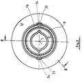
- the location of the opening 23 and the cutout 24 can best be seen from FIG. 4.
- the protective funnel 12 in addition in the direction of rotation around the longitudinal axis 7 around the connection cap 9 is set.
- the Provide connection cap 9 with two wedges 33 offset by 180 °, towards the end, i.e. towards the protective tube 8 have inclined surfaces that are easier to slide open and centering the mounting portion 16 with its grooves Allow 34.
- the wedges 33 and grooves are in the assembled state 34 but with a flat surface, so that a fuse in Direction of rotation is given.
- the protective funnel 12 is in its connection cap withdrawn in the direction of the protective tube 8 position shown so that the universal joint 2 for lubrication for example, the bearing of the cross 5 or the slide ring 10 and the sliding parts is accessible.
- the connector cap 9 meets with her Bore on the contact surface 31 of the spring bolt 22 and leaves this in a position approximated with respect to the longitudinal axis 7 spring back so that the fastening portion 16 the nose 30th can happen until the assembly position is reached and the Nose 30 again radially outwards to fix the fastening section 16 springs.
Description
Die Erfindung betrifft eine Schutzvorrichtung für eine Gelenkwelle, wobei die Gelenkwelle aus zwei Kreuzgelenken, umfassend jeweils zwei Gelenkgabeln und ein beide gelenkig verbindendes Zapfenkreuz, und aus einer aus zwei ineinandergesteckten Schiebeprofilen bestehenden Verbindungswelle, welche mit jeweils einer der Gelenkgabeln der beiden Kreuzgelenke verbunden sind, aufgebaut ist, mit zwei zur koaxialen Anordnung zu der Verbindungswelle und zur Längsachse derselben bestimmten, ineinandergesteckten Schutzrohren, mit jeweils einer Anschlußkappe, einem Gleitring und einem Schutztrichter je Gelenk, der zur zumindest teilweisen axialen Überdeckung des zugehörigen Gelenkes bestimmt ist, wobei jeweils ein Schutztrichter, ein Schutzrohr sowie ein Gleitring mit einer Anschlußkappe verbunden sind und der Gleitring zur Lagerung in einer Nut einer Gelenkgabel des zugehörigen Gelenkes bestimmt ist und der Schutztrichter auch bei an der Gelenkwelle montierter Schutzvorrichtung lösbar an der Anschlußkappe festgelegt ist, wobei die Anschlußkappe mit einer Sitzfläche ausgestattet ist, auf welche der Schutztrichter mit einem Befestigungsabschnitt aufsteckbar und mittels Riegelmitteln festlegbar und durch manuellen Eingriff lösbar ist.The invention relates to a protective device for a cardan shaft, the propeller shaft comprising two universal joints two articulated forks each and one articulatingly connecting both Pin cross, and one of two nested sliding profiles existing connection shaft, which with each one of the joint forks of the two universal joints is connected, is constructed with two for coaxial arrangement to the connecting shaft and mated to the longitudinal axis of the same Protection tubes, each with a connection cap, one Slide ring and a protective funnel per joint, which at least partial axial coverage of the associated joint is determined is, with a protective funnel, a protective tube and a Slide ring are connected to a connection cap and the slide ring for storage in a groove of a joint fork of the associated Joint is determined and the protective funnel also at the PTO shaft mounted protection device detachable on the connection cap is set, the connection cap with a seat is equipped, on which the protective funnel with a Attachment section attachable and by means of locking means can be fixed and released by manual intervention.
Eine solche Schutzvorrichtung ist in der DE 32 08 541 C2 beschrieben.
Zur lösbaren Verbindung zwischen dem Schutztrichter
und der Anschlußkappe wird der Schutztrichter im Bereich seines
Befestigungsabschnittes mit parallel zur Längsachse verlaufenden
Durchlässen für der Anschlußkappe zugeordnete Sperrzungen versehen.
Nach Passieren der Sperrzungen wird der Schutztrichter um
einen bestimmten Winkelweg gegenüber der Anschlußkappe verdreht,
so daß die Sperrzungen den Befestigungsabschnitt des Schutztrichters
in dieser Stellung axial festlegen. Diese Maßnahme ist
jedoch nicht ausreichend, um eine sichere Festlegung für alle
Betriebszustände zu erreichen, denn es treten während der Rotation
der Gelenkwelle im Verhältnis zum stillstehenden Schutz
Vibrationen auf, die eine Verlagerung des Schutztrichters gegenüber
den Sperrzungen ermöglichen könnten. Aus diesem Grunde sind
zusätzliche Maßnahmen vorgesehen, beispielsweise in Form einer
Schraube, die den Schutztrichter im Verhältnis zur Anschlußklappe
auch in Drehrichtung festlegt, wenn sie festgezogen wird.Such a protective device is described in
Der Erfindung liegt die Aufgabe zugrunde, eine Schutzvorrichtung vorzuschlagen, bei der mit dem Aufschieben des Schutztrichters mit seinem Befestigungsabschnitt auf die entsprechende Sitzfläche der Anschlußkappe eine Verriegelung des Schutztrichters zur Anschlußkappe sowohl im Drehsinne als auch in axialer Richtung gegen Abziehen erzielt wird.The invention has for its object a protective device to propose when pushing the protective funnel with its fastening section on the corresponding seat the connection cap locks the protective funnel Connection cap both in the direction of rotation and in the axial direction against stripping is achieved.
Diese Aufgabe wird erfindungsgemäß dadurch gelöst, daß der Befestigungsabschnitt des Schutztrichters und die Anschlußkappe Mittel zur formschlüssigen Verbindung der beiden in Drehrichtung um die Längsachse aufweisen, welche, bezogen auf die Längsachse, ein axiales Aufschieben und Abziehen des Schutztrichters erlauben, daß die Anschlußkappe und der Befestigungsabschnitt des Schutztrichters mit Anschlägen zur Festlegung des Schutztrichters in einer Richtung entlang der Längsachse von dem angeschlossenen Schutzrohr weg versehen sind und daß ferner mindestens ein federnder Riegel vorhanden ist, der beim Aufschieben des Schutztrichters mit seinem Befestigungsabschnitt auf die Sitzfläche der Anschlußkappe in eine zurückgezogene Position überführbar ist und nach Erreichen der Montageposition der beiden zueinander den Befestigungsabschnitt mit einer Riegelfläche, die an einer entsprechenden Gegenfläche des Befestigungsabschnittes angreift, in Richtung auf das Schutzrohr zu festlegt. This object is achieved in that the fastening section of the protective funnel and the connection cap means for the positive connection of the two in the direction of rotation have the longitudinal axis which, relative to the longitudinal axis, allow the protective funnel to be pushed on and pulled off axially, that the connection cap and the fastening section of the Protective funnel with stops for defining the protective funnel in a direction along the longitudinal axis of the connected Protection tube are provided away and that at least a resilient bolt is present, which when pushed open of the protective funnel with its fastening section on the Seat of the connector cap in a retracted position is transferable and after reaching the assembly position of the two to each other the fastening section with a locking surface, on a corresponding counter surface of the fastening section attacks in the direction of the protective tube.
Von Vorteil bei dieser Maßnahme ist, daβ die Sitzverhältnisse von Schutztrichter und Anschlußkappe so ausgelegt werden können, daß der Schutztrichter zur Freigabe der Gelenkbauteile leicht nach Betätigung der federnden Riegel zurückgeschoben werden kann und trotzdem durch den Formschluß in Drehrichtung um die Längsachse nach dem Wiederaufschieben kein Losrütteln durch auftretende Vibrationen möglich ist. Das Zurückschieben des Trichters ist erforderlich, um die von diesem abgedeckten Gelenkbauteile zugänglich zu machen, um beispielsweise die Zapfenkreuzgarnitur des überdeckten Gelenkes oder die Lagerstelle für die Schutzvorrichtung auf der Gelenkgabel des überdeckten Gelenkes für die Schiebeprofile zur Abschmierung zugänglich zu machen. Durch Aufschieben des Schutztrichters mit seinem Befestigungsabschnitt auf die entsprechende Sitzfläche der Anschlußkappe werden die federnden Riegel selbsttätig aktiv, indem sie nach Erreichen der Montageposition von Anschlußkappe und Befestigungsabschnitt zueinander automatisch unter der Federkraft den Befestigungsabschnitt im Bereich seiner Gegenfläche hintergreifen und somit den Schutztrichter zur Anschlußkappe in Richtung der Längsachse festlegen. Die drehfeste Verbindung wird durch den Formschluß zwischen dem Befestigungsabschnitt und der Anschlußkappe erzielt.The advantage of this measure is that the seating conditions of the protective funnel and connection cap can be designed that the protective funnel for releasing the joint components easily can be pushed back after actuation of the resilient latch and nevertheless by the positive connection in the direction of rotation around the longitudinal axis after being pushed back on, there is no shaking Vibrations is possible. Pushing the funnel back is required to cover the hinge components covered by this to make it accessible, for example, the cross member set of the covered joint or the bearing point for the protective device on the joint fork of the covered joint for the To make sliding profiles accessible for lubrication. By Slip on the protective funnel with its fastening section on the corresponding seat of the connection cap spring latch automatically active by reaching after reaching the Mounting position of connection cap and fastening section to each other automatically under the spring force the fastening section reach behind in the area of its counter surface and thus the protective funnel to the connection cap in the direction of Define the longitudinal axis. The non-rotatable connection is made by the Positive locking between the fastening section and the connection cap achieved.
Eine besonders günstige Gestaltung wird dadurch erzielt, daß der federnde Riegel dem Gleitring zugeordnet und einstückig mit diesem ausgebildet ist. Der Gleitring ist in der Regel aus einem hochwertigen Kunststoff hergestellt, der auch günstige federnde Eigenschaften aufweist. Somit ist es besonders günstig, wenn der bzw. die Riegel diesem zugeordnet ist/sind und beispielsweise im Wege des Spritzgießens einstückig mit dem Gleitring hergestellt wird/werden.A particularly favorable design is achieved in that the resilient bolt assigned to the slide ring and in one piece with this is trained. The slip ring is usually made of one Made of high quality plastic, which is also cheap springy Has properties. It is therefore particularly favorable if the or the bolt is / are assigned to it and for example in Injection molding made in one piece with the slide ring will become.
Es ist aber auch eine Zuordnung zur Anschlußkappe möglich, wobei jedoch dann für diese ein entsprechender Kunststoff als Material gewählt werden muß, um die federnden Eigenschaften zu gewährleisten.An assignment to the connection cap is also possible, however but then a corresponding plastic as material for this must be chosen to ensure the resilient properties.
Vorzugsweise besteht der Gleitring aus einem Polyamid als Kunststoff. Um auf Dauer auszuschließen, daß auch ein Kriechen des Kunststoffes oder sonstige Ermüdungserscheinungen zum Ausfall der federnden Eigenschaften des Riegels führen können, ist dem federnden Riegel zur Unterstützung eine metallene Blattfeder zugeordnet. Diese kann vorzugsweise aus einem nicht rostenden Metall bestehen.The slide ring preferably consists of a polyamide as a plastic. To rule out in the long run that a creep of the Plastic or other signs of fatigue to failure the elastic properties of the bolt can lead to resilient latch to support a metal leaf spring assigned. This can preferably be made of a rustproof Metal.
Vorzugsweise sind zwei um 180° um die Längsachse umfangsversetzte federnde Riegel am Gleitring vorgesehen. Die Schutzkappe weist entsprechende Durchbrüche auf, durch die der federnde Riegel mit seiner Riegelfläche radial in den Bereich der Gegenfläche des Befestigungsabschnittes durchtreten kann.Preferably, two are circumferentially offset by 180 ° around the longitudinal axis resilient latch provided on the slide ring. The protective cap has corresponding openings through which the resilient Bolt with its bolt surface radially in the area of the counter surface of the fastening section can pass through.
Eine günstige Gestaltung ergibt sich durch die Anordnung der Gegenfläche des Befestigungsabschnittes in einem radialen Durchbruch oder in einem axialen Ausschnitt. Hierdurch ist gewährleistet, daß der Sperriegel geschützt untergebracht ist und nicht unabsichtlich in seine entriegelte Position überführt werden kann, denn er ragt nicht axial von der Anschlußkappe vor. Vorzugsweise ist bei der Anordnung von zwei um 180° zueinander umfangsversetzten federnden Riegeln vorgesehen, die Gegenfläche für einen Riegel in einem Durchbruch des Befestigungsabschnittes und für den anderen Riegel in einem axialen Ausschnitt anzuordnen. Hierdurch wird erzielt, daß durch die umgrenzte Anordnung in einem Durchbruch ein Öffnen des Riegels nur durch Einsatz eines Werkzeuges ermöglicht wird, während der weitere Riegel durch Druck beispielsweise mit dem Daumen der Hand der Bedienungsperson geöffnet werden kann.A favorable design results from the arrangement of the Counter surface of the fastening section in a radial opening or in an axial cutout. This ensures that the locking bolt is protected and not accidentally transferred to its unlocked position can, because it does not protrude axially from the connection cap. Preferably, when two are arranged at 180 ° to each other circumferentially offset resilient bolts provided the counter surface for a bolt in an opening in the fastening section and to arrange for the other bolt in an axial cutout. This ensures that the delimited arrangement in a breakthrough, opening the bolt only through use one tool is made possible while the further bolt by pressure, for example with the thumb of the operator's hand can be opened.
Hierdurch wird im wesentlichen eine Zwei-Hand-Bedienung erzielt, so daß eine Hand zum Öffnen des einen Riegels und die andere unter Einsatz eines Werkzeuges zum Öffnen des anderen Riegels benutzt werden muß. Insgesamt wird hiermit erreicht, daß nur bewußt ein Öffnen und damit Abziehen des Schutztrichters von seiner Montageposition auf der Anschlußkappe möglich ist.This essentially results in two-hand operation, so one hand to open one latch and the other using a tool to open the other bolt must be used. Overall it is achieved that only deliberately opening and thus removing the protective funnel from its mounting position on the connection cap is possible.
Bei einer solchen Anordnung der Gegenfläche ist in Konkretisierung der Erfindung vorgesehen, die Riegelfläche des federnden Riegels als Bestandteil einer nach außen von der Längsachse wegweisenden Nase auszubilden. Dabei kann die Nase zur Überführung des Riegels in die zurückgezogene Position für den Aufschiebevorgang des Schutztrichters mit seinem Befestigungsabschnitt auf die Anschlußkappe in die Montageposition mit einer Anlauffläche versehen sein, die mit dem Befestigungsabschnitt zusammenarbeitet. Nach Erreichen der Montageposition federt der Riegel automatisch nach außen und legt sich mit seiner Riegelfläche hinter die Gegenfläche des Befestigungsabschnittes. Hierbei kann die Nase mit einer Vertiefung zum Angriff eines Werkzeuges, beispielsweise eines Schraubendrehers versehen sein, der von Hand in die Vertiefung eingeführt wird und danach durch Kippen sich gegen die Wandung des Durchbruches anlegt und somit ein Aufhebeln des federnden Riegels erzielen läßt.With such an arrangement the counter surface is in concretization provided the locking surface of the resilient Riegel as part of an outward from the longitudinal axis to develop a pioneering nose. The nose can be used for transfer of the latch in the retracted position for the opening process of the protective funnel with its fastening section on the connection cap in the mounting position with a Be provided with the attachment portion works together. After reaching the assembly position, the Bolt automatically to the outside and lies down with its bolt surface behind the counter surface of the fastening section. Here can the nose with a recess to attack a tool, for example a screwdriver, which is inserted into the recess by hand and then through Tilt against the wall of the breakthrough and thus can achieve a pry open the resilient bolt.
Nach einer weiteren Ausgestaltung der Erfindung ist der Schutztrichter mehrteilig ausgebildet und er besteht aus einem Bauteil, das den Befestigungsabschnitt darstellt und aus einem Schutzelement. Hierdurch ist es möglich, den Befestigungsabschnitt selbst relativ steif auszubilden, während das Schutzelement in der geforderten Richtung, nämlich Axialrichtung, weicher gestaltet werden kann. Der Befestigungsabschnitt und das Schutzelement sind danach fest miteinander, beispielsweise durch Formschluß, verbunden und zum gemeinsamen Verbinden oder Lösen mit der Anschlußkappe vorgesehen.According to a further embodiment of the invention, the protective funnel is formed in several parts and it consists of one component, that represents the mounting section and from one Protective element. This makes it possible to attach the section train themselves relatively stiff while the protective element in the required direction, namely axial direction, softer can be designed. The mounting section and that Protection element are then firmly together, for example by Positive locking, connected and for joint connection or disconnection provided with the connection cap.
Nach einem weiteren wichtigen Ausgestaltungsmerkmal wird die formschlüssige Verbindung dadurch erreicht, daß die Anschlußkappe um die Längsachse umfangsverteilte und radial nach außen über die Sitzfläche vorstehende Keile und der Befestigungsabschnitt des Schutztrichters entsprechend verteilte und ausgebildete, parallel zur Längsachse verlaufende Nuten aufweist.After another important design feature, the positive connection achieved in that the connection cap distributed around the longitudinal axis and radially outwards the seat protruding wedges and the fastening section of the protective funnel appropriately distributed and trained, has grooves running parallel to the longitudinal axis.
Ein bevorzugtes Ausführungsbeispiel der erfindungsgemäßen Schutzvorrichtung und die wesentlichen Einzelteile sind in der Zeichnung schematisch in Anwendung auf eine Gelenkwelle für den Antrieb einer Landmaschine dargestellt.A preferred embodiment of the invention Protection device and the essential items are in the Drawing schematically applied to a propeller shaft for the Drive of an agricultural machine shown.
Es zeigt
Figur 1- eine für den Antrieb von Landmaschinen vorgesehene landwirtschaftliche Gelenkwelle im Halblängsschnitt mit einer erfindungsgemäßen Schutzvorrichtung,
Figur 2- im vergrößerten Maßstab die Anordnung des Schutztrichters
mit dem Befestigungsabschnitt für das in
Figur 1 dargestellte linke Gelenk im Längsschnitt gemäß Schnittlinie II-II von Figur 3, - Figur 2a
- das Detail X gemäß
Figur 2 im nochmals vergrößerten Maßstab, - Figur 3
- einen Schnitt III-III gemäß
Figur 2 und Figur 4- eine Ansicht mit einem Schnittverlauf vergleichbar zu
Figur 2, wobei jedoch der Schutztrichter von der Anschlußkappe abgezogen ist.
- Figure 1
- an agricultural propeller shaft intended for driving agricultural machinery in a semi-longitudinal section with a protective device according to the invention,
- Figure 2
- on an enlarged scale the arrangement of the protective funnel with the fastening section for the left joint shown in FIG. 1 in longitudinal section according to section line II-II of FIG. 3,
- Figure 2a
- detail X according to FIG. 2 on a further enlarged scale,
- Figure 3
- a section III-III of Figure 2 and
- Figure 4
- a view with a section similar to Figure 2, but with the protective funnel removed from the connector cap.
In Figur 1 ist eine Gelenkwelle 1 mit einer erfindungsgemäßen
Schutzvorrichtung dargestellt. Die Gelenkwelle 1 umfaßt zwei
Kreuzgelenke 2, 2'. Jedes der beiden Kreuzgelenke 2,2' besteht
aus zwei Gelenkgabeln 3, 4, von denen eine zum Anschluß an ein
treibendes oder getriebenes Glied, beispielsweise eine Zapfwelle
eines Traktors, bzw. den Antriebszapfen eines landwirtschaftlichen
Gerätes, bestimmt ist und wobei die beiden Gelenkgabeln 3,
4 durch ein Zapfenkreuz 5 gelenkig miteinander verbunden sind.In Figure 1 is a
Zwischen den beiden Kreuzgelenken 2, 2' ist eine Verbindungswelle
6 angeordnet, die aus zwei ineinandergesteckten und teleskopierbaren
Schiebeprofilen 6', 6'' besteht.Between the two
Die Längenveränderung erfolgt entlang der Längsachse 7.The change in length takes place along the
Die Schutzvorrichtung umfaßt zwei koaxial zu den Schiebeprofilen
6', 6'' angeordnete Schutzrohre 8, 8', die mittels Anschlußkappen
9 und Gleitring 10, der in eine Nut 11 der zugehörigen Gelenkgabel
4 eingreift, am Gelenk festgelegt sind. Ferner ist
jeder Anschlußkappe 9 ein Schutztrichter 12 zugeordnet, der das
darunter befindliche Kreuzgelenk 2, 2' zumindest teilweise überdeckt.
Bei Betrieb ist die Schutzvorrichtung beispielsweise
durch eine Kette oder ein sonstiges Glied festgelegt, so daß nur
die Gelenkwelle 1 rotiert und die Schutzvorrichtung feststeht.The protective device comprises two coaxial to the sliding profiles
6 ', 6' 'arranged
Wie aus den Figuren 2, 2a ersichtlich, umfaßt die Anschlußkappe
9 eine Sitzfläche 15 für den Schutztrichter 12, einen rohrförmigen
Abschluß als Schutzrohranschluß 13 zur Verbindung mit dem
Schutzrohr 8 sowie Mittel zur Festlegung gegenüber dem Gleitring
10. Diese Mittel bestehen aus einer Riegelnase 14, die den
Gleitring 10 in axialer Richtung zwischen zwei Anschlägen festlegt.
Darüber hinaus hält die Anschlußkappe 9 den Gleitring 10
in radialer Richtung gegen Aufweitung. Dem Gleitring 10 sind in
Richtung auf das Schutzrohr 8, das heißt im wesentlichen in
Richtung der Längsachse 7 vorstehend zwei federnde Riegel 22
angeformt, die um 180° um die Längsachse herum versetzt zueinander
angeordnet sind.As can be seen from FIGS. 2, 2a, the connection cap comprises
9 a
Jeder federnde Riegel 22 besitzt an seinem freien Ende eine Nase
30, die von der Längsachse 7 radial nach außen vorragt und in
Richtung auf das zugehörige Kreuzgelenk 2 zu eine Riegelfläche
28 besitzt. In Richtung auf das Schutzrohr 8 zu besitzt die Nase
30 eine schräg verlaufende Anlauffläche 31, in der eine Vertiefung
32 zum Angriff eines Werkzeuges angebracht ist.Each
Der Schutztrichter 12 besteht aus einem Schutzelement 17 aus
einem ersten Werkstoff und einem Befestigungsabschnitt 16 aus
einem Werkstoff höherer Qualität. Es ist jedoch auch möglich,
daß bei Vorliegen eines entsprechenden Materiales und Vorliegen
entsprechender Herstellungsmethoden der Befestigungsabschnitt 16
und das Schutzelement 17 ein Bauteil darstellen können.The
Der Befestigungsabschnitt 16 besitzt eine Bohrung 18, die zur
Sitzfläche 15 der Anschlußkappe 9 passend ausgebildet ist. Ferner
besitzt der Befestigungsabschnitt 16 zwei Anschläge 19, 20,
zwischen denen das Schutzelement 17 festgelegt ist. Somit bilden
Schutzelement 17 und Befestigungsabschnitt 16 im wesentlichen
ein Bauteil, das entweder auf die Anschlußkappe 9 aufgeschoben
oder von dieser gelöst werden kann. Zur Festlegung des Befestigungsabschnittes
16 und damit des Schutztrichters 12 auf der Anschlußkappe
9 dienen in Richtung der Längsachse 7 Anschläge 21,
26 einerseits und zwei federnde Riegel 22 mit einer Riegelfläche
28 andererseits, die an die entsprechende Gegenflächen 29, 29'
des Befestigungsabschnittes 16 zur Anlage kommen. Die beiden Anschläge
21, 26 sichern den Schutztrichter 12 gegen eine Bewegung
in Richtung auf das Kreuzgelenk 2 zu, während die Riegelflächen
28 in Verbindung mit den Gegenflächen 29 oder 29' zur Sicherung
in der dazu entgegengesetzten Richtung entlang der Längsachse 7
dienen. Dabei ist die Gegenfläche 29 Bestandteil eines radialen
Durchbruches 23 des Befestigungsabschnittes für einen ersten
Riegel 22 und die Gegenfläche 29' Bestandteil eines Ausschnittes
24 für einen zweiten Riegel 22. Der Ausschnitt 24 geht von der
Endfläche 25 des Befestigungsabschnittes 16 aus. Er ist zu dieser
hin offen. Die Lage des Durchbruches 23 und des Ausschnittes
24 sind am besten aus Figur 4 erkennbar.The
Durch die Anordnung der Nase 30 eines federnden Riegels 22 in
einem Durchbruch 23 ist es nicht möglich, diesen von Hand zu
betätigen. Hierzu ist ein Werkzeug erforderlich, beispielsweise
ein Schraubendreher, der mit seiner Spitze in die Vertiefung 23
eingesteckt und so beaufschlagt werden kann.By arranging the
Es ist zur Sicherung zusätzlich möglich, die Riegelfläche 28 und
Gegenfläche 29 bzw. 29' geringfügig geneigt verlaufen zu lassen,
so daß sich bei Beaufschlagung durch den Befestigungsabschnitt
16 in Richtung der Längsachse 7 auf das angeschlossene Schutzrohr
8 zu eine positive Verriegelung ergibt. Die Nase 30 des
zweiten Riegels, der mit dem Ausschnitt 24 zusammenwirkt und
nicht besonders dargestellt ist, kann aufgrund der Gestaltung
als Ausschnitt von Hand betätigt werden, so daß für das Lösen
des Schutztrichters 12 von der Anschlußkappe 9 ein Riegel 22 von
Hand und der andere nur mit einem Werkzeug gelöst werden kann.It is also possible to secure the locking
Um zu gewährleisten, daß der federnde Riegel auch bei Eintritt
eventueller Ermüdung seine Riegelfunktion nicht verliert, ist
diesem eine Blattfeder 27 zugeordnet, die ihn unterstützt. Dabei
stützt sich das eine Ende der Blattfeder 27 gegen die Unterseite
des federnden Riegels 22 und die andere Seite gegen den Gleitring
10 ab. To ensure that the spring bolt even when entering
possible fatigue does not lose its locking function
this assigned a leaf spring 27 that supports him. there
one end of the leaf spring 27 is supported against the underside
of the
Aus Figur 3 ist erkennbar, daß der Schutztrichter 12 zusätzlich
in Drehrichtung um die Längsachse 7 herum an der Anschlußkappe
9 festgelegt ist. Hierzu ist, wie Figur 3 zu entnehmen ist, die
Anschlußkappe 9 mit zwei um 180° versetzten Keilen 33 versehen,
die zu ihrem Ende, das heißt in Richtung auf das Schutzrohr 8
hin geneigte Flächen aufweisen, die ein leichteres Aufschieben
und Zentrieren des Befestigungsabschnittes 16 mit seinen Nuten
34 erlauben. Im montierten Zustand liegen die Keile 33 und Nuten
34 jedoch mit ebenen Fläche aneinander, so daß eine Sicherung in
Drehrichtung gegeben ist.From Figure 3 it can be seen that the
In der Figur 4 ist der Schutztrichter 12 in seiner von der Anschlußkappe
in Richtung auf das Schutzrohr 8 abgezogenen Position
dargestellt, so daß das Kreuzgelenk 2 für eine Abschmierung
beispielsweise der Lagerung des Zapfenkreuzes 5 bzw. des Gleitringes
10 und der Schiebeteile zugänglich ist. Wird der Schutztrichter
12 ausgehend von seiner in Figur 4 dargestellten Position
wieder auf die Anschlußkappe 9 mit seinem Befestigungsabschnitt
16 aufgeschoben, so trifft die Anschlußkappe 9 mit ihrer
Bohrung auf die Anlauffläche 31 der federnden Riegel 22 und läßt
diese in eine bezogen auf die Längsachse 7 angenäherte Position
zurückfedern, damit der Befestigungsabschnitt 16 die Nase 30
passieren kann, bis die Montageposition erreicht ist und die
Nase 30 wieder radial auswärts zur Festlegung des Befestigungsabschnittes
16 federn kann. In FIG. 4, the
- 11
- GelenkwellePTO shaft
- 2, 2'2, 2 '
- KreuzgelenkUniversal joint
- 3, 43, 4
- GelenkgabelJoint fork
- 55
- ZapfenkreuzCone cross
- 66
- VerbindungswelleConnecting shaft
- 6', 6"6 ', 6 "
- SchiebeprofileSliding profiles
- 77
- LängsachseLongitudinal axis
- 8, 8'8, 8 '
- SchutzrohrProtective tube
- 99
- AnschlußkappeConnection cap
- 1010th
- GleitringSlide ring
- 1111
- NutGroove
- 1212th
- SchutztrichterProtective funnel
- 1313
- SchutzrohranschlußProtection tube connection
- 1414
- RiegelnaseBolt nose
- 1515
- SitzflächeSeat
- 1616
- BefestigungsabschnittFastening section
- 1717th
- SchutzelementProtective element
- 1818th
- Bohrungdrilling
- 19, 2019, 20
- Anschlag am BefestigungsabschnittStop on the fastening section
- 2121
- Axialanschlag an der AnschlußkappeAxial stop on the connection cap
- 2222
- federnder Riegelspring bolt
- 2323
- Durchbruch im BefestigungsabschnittBreakthrough in the fastening section
- 2424th
- Ausschnitt im BefestigungsabschnittCutout in the fastening section
- 2525th
- Endfläche des Befestigungsabschnittes End surface of the fastening section
- 2626
- Axialanschlag am BefestigungsabschnittAxial stop on the fastening section
- 2727
- BlattfederLeaf spring
- 2828
- RiegelflächeBolt surface
- 29, 29'29, 29 '
- GegenflächeCounter surface
- 3030th
- Nasenose
- 3131
- AnlaufflächeContact area
- 3232
- Vertiefungdeepening
- 3333
- Keilwedge
- 3434
- NutGroove
Claims (11)
- A protective device for a driveshaft (1), wherein the driveshaft (1) is composed of two universal joints (2, 2') each comprising two joint yokes (3, 4) and a cross member (5) articulatably connecting said two joint yokes (3, 4), and of a connecting shaft (6) which consists of two plunging profiles (6', 6'') inserted into one another and which are respectively connected to one of the joint yokes (4) of the two universal joints (2, 2'), having two protective tubes (8, 8') which are inserted into one another and which are intended to be arranged co-axially relative to the connecting shaft (6) and relative to the longitudinal axis (7) of same, having one attaching cap (9), one sliding ring (10) and one protective cone (12) each per universal joint (2, 2'), with said protective cone (12) being provided for at least partially axially covering the associated universal joint (2, 2'), wherein one protective cone (12), one protective tube (8, 8') and one sliding ring (10) are connected to an attaching cap (9) and wherein the sliding ring (10) is intended to be supported in a groove (11) of a joint yoke (4) of the associated universal joint (2, 2'), with the protective cone (12) being releasably secured to the connecting cap (9), even if the protective device is mounted on the driveshaft, wherein the attaching cap (9) is provided with a seat face (15) on to which the protective cone (12) can be slid by means of a fixing portion (16) and secured by locking means and from which it can be released manually,
characterised in
that the fixing portion (16) of the protective cone (12) and the attaching cap (9) comprise means (33, 34) for providing a form-fitting connection between said two parts in the direction of rotation around the longitudinal axis (7), which means (33, 34), with reference to the longitudinal axis (7), permit the protective cone (12) to be axially slid on and pulled off; that the attaching cap (9) and the fixing portion (16) of the protective cone (12) are provided with stops (21, 26) for securing the protective cone (12) in a direction along the longitudinal axis (7) away from the attached protective tube (8, 8'); and that, furthermore, there is provided at least one resilient locking element (22) which can be transferred into a withdrawn position while the protective cone (12) is being slid by means of its fixing portion (16) on to the seat face (15) of the attaching cap (9) and which, after the mounted position of the two relative to one another has been reached, secures the fixing portion (16) in the direction towards the protective tube (8, 8') by means of a locking face (28) acting on a corresponding counter face (29, 29') of the fixing portion (16). - A protective device according to claim 1,
characterised in
that the resilient locking element (22) is associated with the sliding ring (10) and produced so as to be integral therewith. - A protective device according to any one of claims 1 or 2,
characterised in
that the sliding ring (10) consists of plastics, especially polyamide and is associated with the resilient locking element (22) for the purpose of supporting a metal leaf spring (27). - A protective device according to any one of claims 1 to 3,
characterised in
that there are provided two resilient locking elements (22) circumferentially offset around the longitudinal axis (7) by 180°. - A protective device according to any one of claims 1 to 4,
characterised in
that the counter face (29) of the fixing portion (16) is arranged in a radial aperture (23) of the fixing portion (16). - A protective device according to any one of claims 1 to 4,0
characterised in
that the counter face (29') of the fixing portion (16) is arranged in a cut-out (24) of the fixing portion (16). - A protective device according to any one of claims 5 or 6,
characterised in
that the locking face (28) forms part of a nose (30) projecting outwardly from the longitudinal axis (7). - A protective device according to claim 7,
characterised in
that for the purpose of transferring the locking element (22) into the withdrawn position, the nose (30) is provided with a stop face (31). - A protective device according to claim 7,
characterised in
that the nose (30) comprises an indentation (32) to allow engagement of a tool. - A protective device according to any one of claims 1 to 5,
characterised in
that the protective cone (12) is of the multi-part design, i.e. it consists of a component constituting the fixing portion (16) and of a protective element (17). - A protective device according to claim 1,
characterised in
that to achieve a form-fitting connection between the fixing portion (16) of the protective cone (12) and the attaching cap (9), the attaching cap (9) is provided with wedges (33) which are circumferentially distributed around the longitudinal axis (7) and project outwardly from the seat face, and the fixing portion (16) of the protective cone (12) is provided with correspondingly distributed and shaped grooves (34) extending parallel to the longitudinal axis (7).
Applications Claiming Priority (2)
| Application Number | Priority Date | Filing Date | Title |
|---|---|---|---|
| DE19541511 | 1995-11-08 | ||
| DE19541511A DE19541511C1 (en) | 1995-11-08 | 1995-11-08 | Protective device for cardan shafts with a removable protective funnel |
Publications (2)
| Publication Number | Publication Date |
|---|---|
| EP0773383A1 EP0773383A1 (en) | 1997-05-14 |
| EP0773383B1 true EP0773383B1 (en) | 2001-07-18 |
Family
ID=7776853
Family Applications (1)
| Application Number | Title | Priority Date | Filing Date |
|---|---|---|---|
| EP96116668A Expired - Lifetime EP0773383B1 (en) | 1995-11-08 | 1996-10-26 | Protective device for articulated shafts with removable protective cone |
Country Status (15)
| Country | Link |
|---|---|
| US (1) | US5800271A (en) |
| EP (1) | EP0773383B1 (en) |
| JP (1) | JP2875514B2 (en) |
| AU (1) | AU693043B2 (en) |
| BR (1) | BR9605482A (en) |
| CA (1) | CA2189716C (en) |
| CZ (1) | CZ287554B6 (en) |
| DE (1) | DE19541511C1 (en) |
| DK (1) | DK0773383T3 (en) |
| ES (1) | ES2159338T3 (en) |
| HU (1) | HU221052B1 (en) |
| NO (1) | NO310318B1 (en) |
| RO (1) | RO116117B1 (en) |
| RU (1) | RU2117196C1 (en) |
| SK (1) | SK280390B6 (en) |
Families Citing this family (11)
| Publication number | Priority date | Publication date | Assignee | Title |
|---|---|---|---|---|
| IT1286696B1 (en) * | 1996-08-14 | 1998-07-15 | Edi Bondioli | CARDAN TRANSMISSION SHAFT IN SCOPE SPECIES, WITH PROTECTIVE SHEATH AND PROTECTIVE CAPS OF THE TERMINAL FORKS |
| IT1288372B1 (en) * | 1996-11-08 | 1998-09-22 | Eurocardan S P A | PROTECTIVE GUARD DEVICE WITH RING WITH SHAFT, IN PARTICULAR PTO SHAFT. |
| DE19744314C2 (en) * | 1997-10-08 | 1999-09-02 | Walterscheid Gmbh Gkn | Protection device for a cardan shaft |
| DE19744313C2 (en) * | 1997-10-08 | 1999-08-26 | Walterscheid Gmbh Gkn | Protection device for a universal joint of a cardan shaft |
| US9005041B2 (en) * | 2013-02-08 | 2015-04-14 | Omni Usa, Inc. | Driveline shield assembly |
| ITMO20130219A1 (en) * | 2013-07-31 | 2015-02-01 | Comer Ind Spa | PROTECTION DEVICE FOR CARDANIC TRANSMISSIONS |
| RU182201U1 (en) * | 2018-02-22 | 2018-08-07 | Открытое акционерное общество "Саратовский завод "Серп и Молот" | Cardan shaft with protective device for movable spline connection |
| CN108361291A (en) * | 2018-02-27 | 2018-08-03 | 安徽江淮汽车集团股份有限公司 | A kind of transmission shaft inputs Axile connection structure with rear axle |
| WO2021089515A1 (en) * | 2019-11-07 | 2021-05-14 | Lusetti, Lea | Drive shaft with lubricated accident-prevention end protections |
| IT202000014905A1 (en) * | 2020-06-22 | 2021-12-22 | Luisetti Lea | A PROTECTION SYSTEM FOR A CARDAN SHAFT AND A CARDAN SHAFT INCLUDING THE SAID PROTECTION SYSTEM |
| US11796009B1 (en) * | 2023-01-27 | 2023-10-24 | Ryan D. Hunter | Cover for a universal joint of a driveshaft |
Family Cites Families (12)
| Publication number | Priority date | Publication date | Assignee | Title |
|---|---|---|---|---|
| DE2327482C2 (en) * | 1973-05-30 | 1974-08-08 | Jean Walterscheid Gmbh, 5204 Lohmar | Protective device for cardan shafts |
| DE3026062C2 (en) * | 1980-07-10 | 1982-05-13 | Jean Walterscheid Gmbh, 5204 Lohmar | Protective device for a cardan shaft |
| DE3026135C1 (en) * | 1980-07-10 | 1981-10-15 | Jean Walterscheid Gmbh, 5204 Lohmar | Protection device for a cardan shaft |
| IT1167912B (en) * | 1981-06-05 | 1987-05-20 | Edi Bondioli | PROTECTION WITH MODULAR ELEMENTS FOR CARDANIC TRANSMISSION SHAFTS |
| IT1167944B (en) * | 1981-07-14 | 1987-05-20 | Edi Bondioli | PROTECTION DEVICE OF THE END FORK OF A TRANSMISSION CARDANIC SHAFT FOR AGRICULTURAL MACHINES AND OTHER |
| DE3208541C1 (en) * | 1982-03-10 | 1983-06-01 | Jean Walterscheid Gmbh, 5204 Lohmar | Protection device for a cardan shaft |
| IT1173420B (en) * | 1984-03-01 | 1987-06-24 | Benzi & Di Terlizzi Snc | METHOD OF MANUFACTURE OF A MEANS OF PROTECTION FOR CARDANIC TRANSMISSION SHAFT AND MEANS OF PROTECTION OBTAINED WITH THE METHOD |
| JPS6245427A (en) * | 1985-08-20 | 1987-02-27 | Sankyo Alum Ind Co Ltd | Joining face forming method for shape material |
| JPS6245427U (en) * | 1985-09-06 | 1987-03-19 | ||
| JP2583293B2 (en) * | 1988-09-27 | 1997-02-19 | 光洋精工株式会社 | Cover for propeller shaft |
| IT1241741B (en) * | 1990-06-22 | 1994-02-01 | Edi Bondioli | PROTECTION FOR CARDANIC SHAFTS WITH LUBRICATION VEHICLES |
| SE470121B (en) * | 1992-04-24 | 1993-11-15 | Skogs Och Lantbrukshaelsan Ab | bellow |
-
1995
- 1995-11-08 DE DE19541511A patent/DE19541511C1/en not_active Expired - Lifetime
-
1996
- 1996-10-26 ES ES96116668T patent/ES2159338T3/en not_active Expired - Lifetime
- 1996-10-26 EP EP96116668A patent/EP0773383B1/en not_active Expired - Lifetime
- 1996-10-26 DK DK96116668T patent/DK0773383T3/en active
- 1996-10-30 AU AU70502/96A patent/AU693043B2/en not_active Ceased
- 1996-11-05 RO RO96-02086A patent/RO116117B1/en unknown
- 1996-11-05 RU RU96121516A patent/RU2117196C1/en not_active IP Right Cessation
- 1996-11-06 CA CA002189716A patent/CA2189716C/en not_active Expired - Fee Related
- 1996-11-06 SK SK1436-96A patent/SK280390B6/en unknown
- 1996-11-07 NO NO19964711A patent/NO310318B1/en not_active IP Right Cessation
- 1996-11-07 CZ CZ19963274A patent/CZ287554B6/en not_active IP Right Cessation
- 1996-11-07 HU HU9603087A patent/HU221052B1/en not_active IP Right Cessation
- 1996-11-07 JP JP8295246A patent/JP2875514B2/en not_active Expired - Lifetime
- 1996-11-07 BR BR9605482A patent/BR9605482A/en not_active IP Right Cessation
- 1996-11-08 US US08/745,792 patent/US5800271A/en not_active Expired - Lifetime
Also Published As
| Publication number | Publication date |
|---|---|
| RO116117B1 (en) | 2000-10-30 |
| HU221052B1 (en) | 2002-07-29 |
| SK143696A3 (en) | 1997-09-10 |
| CA2189716C (en) | 2000-05-02 |
| JP2875514B2 (en) | 1999-03-31 |
| NO310318B1 (en) | 2001-06-18 |
| ES2159338T3 (en) | 2001-10-01 |
| HUP9603087A2 (en) | 1997-10-28 |
| SK280390B6 (en) | 2000-01-18 |
| US5800271A (en) | 1998-09-01 |
| CA2189716A1 (en) | 1997-05-09 |
| AU693043B2 (en) | 1998-06-18 |
| EP0773383A1 (en) | 1997-05-14 |
| DE19541511C1 (en) | 1997-04-24 |
| RU2117196C1 (en) | 1998-08-10 |
| HU9603087D0 (en) | 1996-12-30 |
| AU7050296A (en) | 1997-05-22 |
| CZ287554B6 (en) | 2000-12-13 |
| HUP9603087A3 (en) | 1999-11-29 |
| NO964711L (en) | 1997-05-09 |
| JPH09170627A (en) | 1997-06-30 |
| CZ327496A3 (en) | 1997-05-14 |
| DK0773383T3 (en) | 2001-11-05 |
| NO964711D0 (en) | 1996-11-07 |
| BR9605482A (en) | 1998-08-11 |
Similar Documents
| Publication | Publication Date | Title |
|---|---|---|
| EP0501149B1 (en) | Fastening for securing a coupling sleeve | |
| EP0773383B1 (en) | Protective device for articulated shafts with removable protective cone | |
| WO1999038736A2 (en) | Wiper system | |
| DE102008028396A1 (en) | Connecting arrangement and PTO shaft hereby | |
| EP0908083B1 (en) | Articulated shaft protection device | |
| DE3829749A1 (en) | DEVICE FOR CONNECTING A WORK TOOL TO A TRACTOR | |
| DE3802849C1 (en) | ||
| DE2905363C2 (en) | Shear pin coupling | |
| DE3208541C1 (en) | Protection device for a cardan shaft | |
| EP0618393A1 (en) | Coupling device for hoses and/or circuits | |
| EP1801485A1 (en) | Coupling device for interconnecting multiple fluid lines | |
| DE19709282A1 (en) | Propeller shaft with two universal joints for e.g. rail vehicles | |
| DE2901506C2 (en) | Shear pin coupling | |
| DE19918638A1 (en) | Connection part for borer for boring bone tissue; has inner holder unit with snap-in pin to engage grooves in borer and sliding sleeve that can be moved to lock pin in place | |
| DE10001270A1 (en) | Universal joint has a cylindrical elastomer sleeve between the pin of the pin spider and the pin holder with a radial bearing to transmit forces and torque and reduce noise and vibrations | |
| AT388426B (en) | COUPLING ARRANGEMENT FOR AT LEAST ONE PIPELINE AND SEALING PLUG FOR | |
| DE19510077C1 (en) | Protection for linkages and sliding shaft in agricultural machinery | |
| DE19743585C2 (en) | Device for axially securing a coupling sleeve on a shaft | |
| EP0776775B1 (en) | Wheel bearing | |
| EP1293693A2 (en) | Safety clutch device for power take off on agricultural machines | |
| DE202019103359U1 (en) | Linear drive with coupling | |
| DE2805919C2 (en) | Detachable quick coupling to connect two shafts | |
| DE19653654B4 (en) | Storage of a drive axle | |
| DE3518661A1 (en) | Spanner | |
| DE19744313C2 (en) | Protection device for a universal joint of a cardan shaft |
Legal Events
| Date | Code | Title | Description |
|---|---|---|---|
| PUAI | Public reference made under article 153(3) epc to a published international application that has entered the european phase |
Free format text: ORIGINAL CODE: 0009012 |
|
| 17P | Request for examination filed |
Effective date: 19970315 |
|
| AK | Designated contracting states |
Kind code of ref document: A1 Designated state(s): CH DK ES FI FR GB IT LI NL SE |
|
| GRAG | Despatch of communication of intention to grant |
Free format text: ORIGINAL CODE: EPIDOS AGRA |
|
| 17Q | First examination report despatched |
Effective date: 20000829 |
|
| GRAG | Despatch of communication of intention to grant |
Free format text: ORIGINAL CODE: EPIDOS AGRA |
|
| GRAG | Despatch of communication of intention to grant |
Free format text: ORIGINAL CODE: EPIDOS AGRA |
|
| GRAH | Despatch of communication of intention to grant a patent |
Free format text: ORIGINAL CODE: EPIDOS IGRA |
|
| GRAG | Despatch of communication of intention to grant |
Free format text: ORIGINAL CODE: EPIDOS AGRA |
|
| RBV | Designated contracting states (corrected) |
Designated state(s): CH DK ES FI FR GB IT LI NL SE |
|
| GRAH | Despatch of communication of intention to grant a patent |
Free format text: ORIGINAL CODE: EPIDOS IGRA |
|
| REG | Reference to a national code |
Ref country code: DE Ref legal event code: 8566 |
|
| GRAA | (expected) grant |
Free format text: ORIGINAL CODE: 0009210 |
|
| AK | Designated contracting states |
Kind code of ref document: B1 Designated state(s): CH DK ES FI FR GB IT LI NL SE |
|
| RTI1 | Title (correction) |
Free format text: PROTECTIVE DEVICE FOR ARTICULATED SHAFTS WITH REMOVABLE PROTECTIVE CONE |
|
| REG | Reference to a national code |
Ref country code: CH Ref legal event code: EP |
|
| REG | Reference to a national code |
Ref country code: CH Ref legal event code: NV Representative=s name: PA ALDO ROEMPLER |
|
| ITF | It: translation for a ep patent filed |
Owner name: DE DOMINICIS & MAYER S.R.L. |
|
| GBT | Gb: translation of ep patent filed (gb section 77(6)(a)/1977) |
Effective date: 20010831 |
|
| REG | Reference to a national code |
Ref country code: ES Ref legal event code: FG2A Ref document number: 2159338 Country of ref document: ES Kind code of ref document: T3 |
|
| REG | Reference to a national code |
Ref country code: DK Ref legal event code: T3 |
|
| ET | Fr: translation filed | ||
| REG | Reference to a national code |
Ref country code: GB Ref legal event code: IF02 |
|
| PLBE | No opposition filed within time limit |
Free format text: ORIGINAL CODE: 0009261 |
|
| STAA | Information on the status of an ep patent application or granted ep patent |
Free format text: STATUS: NO OPPOSITION FILED WITHIN TIME LIMIT |
|
| 26N | No opposition filed | ||
| PGFP | Annual fee paid to national office [announced via postgrant information from national office to epo] |
Ref country code: SE Payment date: 20021023 Year of fee payment: 7 Ref country code: FI Payment date: 20021023 Year of fee payment: 7 Ref country code: CH Payment date: 20021023 Year of fee payment: 7 |
|
| PG25 | Lapsed in a contracting state [announced via postgrant information from national office to epo] |
Ref country code: FI Free format text: LAPSE BECAUSE OF NON-PAYMENT OF DUE FEES Effective date: 20031026 |
|
| PG25 | Lapsed in a contracting state [announced via postgrant information from national office to epo] |
Ref country code: SE Free format text: LAPSE BECAUSE OF NON-PAYMENT OF DUE FEES Effective date: 20031027 |
|
| PG25 | Lapsed in a contracting state [announced via postgrant information from national office to epo] |
Ref country code: LI Free format text: LAPSE BECAUSE OF NON-PAYMENT OF DUE FEES Effective date: 20031031 Ref country code: CH Free format text: LAPSE BECAUSE OF NON-PAYMENT OF DUE FEES Effective date: 20031031 |
|
| EUG | Se: european patent has lapsed | ||
| REG | Reference to a national code |
Ref country code: CH Ref legal event code: PL |
|
| PGFP | Annual fee paid to national office [announced via postgrant information from national office to epo] |
Ref country code: GB Payment date: 20051011 Year of fee payment: 10 |
|
| PGFP | Annual fee paid to national office [announced via postgrant information from national office to epo] |
Ref country code: ES Payment date: 20051014 Year of fee payment: 10 |
|
| PGFP | Annual fee paid to national office [announced via postgrant information from national office to epo] |
Ref country code: DK Payment date: 20061213 Year of fee payment: 11 |
|
| GBPC | Gb: european patent ceased through non-payment of renewal fee |
Effective date: 20061026 |
|
| PG25 | Lapsed in a contracting state [announced via postgrant information from national office to epo] |
Ref country code: GB Free format text: LAPSE BECAUSE OF NON-PAYMENT OF DUE FEES Effective date: 20061026 |
|
| REG | Reference to a national code |
Ref country code: ES Ref legal event code: FD2A Effective date: 20061027 |
|
| PG25 | Lapsed in a contracting state [announced via postgrant information from national office to epo] |
Ref country code: ES Free format text: LAPSE BECAUSE OF NON-PAYMENT OF DUE FEES Effective date: 20061027 |
|
| REG | Reference to a national code |
Ref country code: DK Ref legal event code: EBP |
|
| PG25 | Lapsed in a contracting state [announced via postgrant information from national office to epo] |
Ref country code: DK Free format text: LAPSE BECAUSE OF NON-PAYMENT OF DUE FEES Effective date: 20071031 |
|
| REG | Reference to a national code |
Ref country code: FR Ref legal event code: PLFP Year of fee payment: 20 |
|
| PGFP | Annual fee paid to national office [announced via postgrant information from national office to epo] |
Ref country code: IT Payment date: 20151026 Year of fee payment: 20 |
|
| PGFP | Annual fee paid to national office [announced via postgrant information from national office to epo] |
Ref country code: FR Payment date: 20151026 Year of fee payment: 20 Ref country code: NL Payment date: 20151026 Year of fee payment: 20 |
|
| REG | Reference to a national code |
Ref country code: NL Ref legal event code: MK Effective date: 20161025 |