EP0773155A1 - Stellwerkanlage für Eisenbahnen mit Logik-Architektur und Implementationsverfahren - Google Patents
Stellwerkanlage für Eisenbahnen mit Logik-Architektur und Implementationsverfahren Download PDFInfo
- Publication number
- EP0773155A1 EP0773155A1 EP96402126A EP96402126A EP0773155A1 EP 0773155 A1 EP0773155 A1 EP 0773155A1 EP 96402126 A EP96402126 A EP 96402126A EP 96402126 A EP96402126 A EP 96402126A EP 0773155 A1 EP0773155 A1 EP 0773155A1
- Authority
- EP
- European Patent Office
- Prior art keywords
- tasks
- task
- network
- message
- route
- Prior art date
- Legal status (The legal status is an assumption and is not a legal conclusion. Google has not performed a legal analysis and makes no representation as to the accuracy of the status listed.)
- Withdrawn
Links
Images


Classifications
-
- B—PERFORMING OPERATIONS; TRANSPORTING
- B61—RAILWAYS
- B61L—GUIDING RAILWAY TRAFFIC; ENSURING THE SAFETY OF RAILWAY TRAFFIC
- B61L19/00—Arrangements for interlocking between points and signals by means of a single interlocking device, e.g. central control
- B61L19/06—Interlocking devices having electrical operation
-
- B—PERFORMING OPERATIONS; TRANSPORTING
- B61—RAILWAYS
- B61L—GUIDING RAILWAY TRAFFIC; ENSURING THE SAFETY OF RAILWAY TRAFFIC
- B61L1/00—Devices along the route controlled by interaction with the vehicle or vehicle train, e.g. pedals
Definitions
- the invention relates to safe train traffic on a rail network, and more particularly to a rail interlocking system based on a software architecture.
- the system includes a rule base, an inference engine, and a data model on which rules are applied to establish and release routes.
- the data model represents the track equipment constituting the network by sorts of logic gates. Each rule defines conditions to be verified by a logic gate before entry by a train to the corresponding track equipment of the network is permitted.
- This interlocking system has the advantage of being much more flexible than traditional relay-based solutions.
- such an interlocking system can be implemented by computer processing of a high level abstraction description file of the network and of the rule base so as to constitute the data model corresponding to the network to be checked.
- the rule base is designed to be generic enough, it can be used for implementing other interlocking systems without modification.
- this known rail interlocking system requires, for its execution, a centralized processing resource in which the rule base, the data model and the inference engine resides. The processing capacities of this resource must be all the more important as the rail network under control is complex since the complexity of the data model increases with that of the network. It is moreover suggested in the document cited above, to exploit a multiprocessor resource which makes it possible to parallelize certain treatments with the drawback of making the maintenance of the system more complex.
- the object of the invention is to propose a rail interlocking system based on a software architecture of another design and capable of being distributed over a plurality of low-cost processing resources such as microcomputers.
- the invention aims to provide such a rail interlocking system capable of exploiting the processing resources already in place in the control / command installations of existing rail networks and serving for the acquisition of signals from track equipment. .
- the subject of the invention is a rail interlocking system based on a software architecture and used for the safe train traffic on a network made up of a plurality of track equipments.
- This system comprises a set of tasks associated respectively with the track equipment constituting the network.
- the tasks implement a distributed logic of establishment and release of routes by propagation of messages through successions of logical communication channels interconnecting the tasks according to a provision corresponding to a certain geographical topology of the railway network under control.
- this distributed message propagation logic is implemented in tasks in the form of finite state machines. Finite state machines interact with each other by propagating messages along logical communication channels.
- the tasks have an asynchronous behavior.
- the great complexity of a rail network to be checked results in a large number of tasks to be performed.
- the tasks have an asynchronous behavior, it is not useful to provide a processing resource of very high capacity for their execution because the tasks can be distributed on a low-performing processing resource set if only a small number of tasks reside in each low-capacity processing resource, the cost of such a low-capacity processing resource being much lower than that '' a single processing resource of equivalent capacity.
- the autonomous and asynchronous operation of the tasks of the solution according to the invention allows simple control of the proper functioning of each task, which contributes to reducing the maintenance costs of the engagement system.
- the invention extends to a method for implementing such a rail interlocking system on the basis of computer processing of a high level abstraction description file of the rail network to be checked and of a library of modules.
- generic software each implementing a finite state machine corresponding to a type of track equipment.
- the library of generic software modules can be used, without modification, to implement different interlocking systems to control different corresponding rail networks.
- Figure 1 schematically shows an integrated electronic control center including the system according to the invention.
- Figure 2 is a block diagram of a rail network.
- FIG. 3 illustrates the software architecture of the system according to the invention adapted to the rail network shown in FIG. 2.
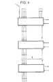
- FIG. 4 is a diagram illustrating the propagation of message streams through tasks associated with a succession of corresponding channel equipment.
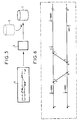
- FIG. 5 illustrates the method for implementing a system according to the invention.
- Figure 6 is a block diagram of a rail network from which a high-level network abstraction description file is made.
- the rail interlocking system 1 is part of a more complex assembly (integrated electronic control center) comprising a control station 2 from which an operator monitors the situation on the rail network 3 under control of the interlocking system.
- a control station 2 from which an operator monitors the situation on the rail network 3 under control of the interlocking system.
- a rail interlocking system is used to establish (interlock) and release routes so as to maintain the safety of traffic on a network.
- interlock it is a question of avoiding the collision of trains on the network.
- a collision can occur if, for example, interlocked routes intersect.
- the interlocking system 1 comprises a set of tasks respectively associated with corresponding channel equipment constituting the network to be controlled and communicating with each other by messages asynchronously as described below.
- the tasks implement a distributed logic for establishing and freeing routes by propagation of messages through successions of logical communication channels each interconnecting a message output of a task and a message input of another task.
- the logical communication channels are implemented between the tasks according to an arrangement corresponding to a certain geographical topology of the network so that each succession of logical communication channels corresponds in fact to a predefined route for the circulation of trains on the network. In other words, for a route passing successively through a succession of track equipment, there is a corresponding succession of logical communication channels which interconnect tasks associated with this equipment.
- FIG. 2 schematically shows a rail network which serves as an example to explain the invention and
- FIG. 3 shows the software architecture of the rail interlocking system corresponding to this example of network.
- the rail network comprises two tracks AE and AB coupled by a switch and serving a station G.
- This network consists, from a functional point of view, of a plurality of track equipment, the relative arrangement of the equipment of track defining a certain geographic topology of the network.
- a first track circuit referenced AEA On the AE track, there is arranged in sequence (from left to right in FIG. 2), a first track circuit referenced AEA, a second track circuit AEB, a multi-aspect signal MP263 (three-color light for example), a first switch MP2205B (electrically controlled), a second switch MP2206A, an operating signal MP1002 (two-color light in particular), a third AED track circuit, a second multi-aspect signal MP265, a fourth AEE track circuit and a fifth circuit AEF track.
- a first track circuit referenced AEA On the AE track, there is arranged in sequence (from left to right in FIG. 2), a first track circuit referenced AEA, a second track circuit AEB, a multi-aspect signal MP263 (three-color light for example), a first switch MP2205B (electrically controlled), a second switch MP2206A, an operating signal MP1002 (two-color light in particular), a third AED track circuit
- a first ABE channel circuit On the AB channel, there are arranged in sequence (from right to left in FIG. 2), a first ABE channel circuit, a second ABG channel circuit, a first multi-aspect signal MP262, a third ABJ channel circuit, a first switch MP2206B, a second switch MP2205A, a second multi-aspect signal MP261, a fourth ABP channel circuit and a fifth ABR channel circuit.
- trains can use different predefined routes, each starting from a multi-aspect signal such as the MP261 signal or from a switching signal and passing through different successions of track equipment.
- a multi-aspect signal such as the MP261 signal or from a switching signal and passing through different successions of track equipment.
- the route referenced R261 in FIG. 2 starts from the multi-aspect signal MP261 and passes successively through the switch MP2205A, the switch MP2206B, the switch MP2206A, the track circuit AED and finally by the multi-aspect signal MP265.
- the signals are or are not part of a route depending on their orientation with respect to the direction of travel of the train on the route.
- FIG 3 the software architecture of the rail interlocking system corresponding to the rail network of Figure 2 shows the geographic topology of this network.
- the tasks are represented by blocks between which appear logical communication channels represented by arrows 6.
- a logical communication channel implemented between two tasks corresponds to part of a route passing through the two associated track equipments. to these two tasks. If a train can travel this part of the route in both directions, the corresponding tasks are interconnected by two logical channels of parallel communication. This is the case for example for the two logical communication channels interconnecting the tasks referenced dPnt-2205A and dPnt-2206B.
- tasks Sig-261, Sig-262, Sig-263 and Sig-265 each associated with a multi-aspect signal
- tasks Trc-AEA, TrcAEB, Trc-AED, Trc-AEE, Trc -AEF, Trc-ABE, Trc-ABG, Trc-ABJ, Trc-ABP and Trc-ABR each associated with a track circuit
- tasks Shi-1002 associated with an operating signal and tasks dPnt-2205A, dPnt- 2205B, dPnt-2206A and dPnt-2206B each associated with a switch.
- the operating principle of the logic distributed by message propagation is described below on the basis of the route R261 and with reference to FIGS. 3 and 4.
- the route R261 corresponds to a succession of the logical communication channels interconnecting in sequence Sig-261, dPnt-2005A, dPnt-2006B, dPnt-2005B, Trc-AED and Sig-265 whose corresponding blocks are shown hatched in Figure 3.
- the entry of route R261 corresponds to task Sig-261.
- the establishment of a route is required from control station 1.
- a request to establish this route sent from control station 1 (symbolized by Sys in FIG. 4) is received by the input task of the route in the form of an entry message including a route identifier.
- task Sig-261 receives the message Req (R261), the route identifier being symbolized by R261.
- a first process for propagating the route establishment request message, from the route entry task and following a loop passing through the series of tasks corresponding to this route and returning to the entry task of the route, is implemented by all of these tasks.
- the message R261 is propagated by the tasks Sig-261, dPnt-2005A, dPnt-2006B, dPnt-2005B, TrcAED and Sig-265 following a loop called allocation loop during which, each task in question s allocates for route R261 on receipt of the Req message (R261) except in the presence of a conflict situation (the task is already allocated for another route).
- a Conf message (R261) is raised, from task to task, from the task in question to the route entry task such as task Sig-261, which transmits this message to the control post.
- a second process is then implemented by the tasks which have been allocated for a route, in order to check that all the track equipment of the route is placed in a correct position (positioning of the needles in particular) before opening the running of a train on the route and, if not, order them to place them in the required position.
- This second process also consists in the propagation of a Ctrl message from task to task, from the entry task of the route and following a loop called the control loop. on receipt of this message, each task commands the correct positioning of the track equipment with which it is associated and recovers in a status signal information relating to the current position occupied by this equipment.
- the message Ctrl (R261, rtechk) is propagated from task to task while the parameter rtechk is updated by each task and each track equipment is ordered to occupy the correct position before the route is opened.
- the Sig-265 task returns the message Ctrl (R261, rtechk) to the Sig-261 task.
- the Sig-261 task When the Sig-261 task receives the Ctrl message (R261, rtechk), it performs processing to check, from the information contained in the rtechk parameter, whether all the track equipment is positioned correctly. If all the track equipment is not positioned correctly, the message Ctrl (R261, rtechk) is propagated again according to the command loop. If the track equipment is all correctly positioned, the Sig-261 task sends the message Set (R261) to the control station to confirm that the route R261 is now established (or initiated) until the occurrence of a release condition.
- the Sig-261 task Upon receipt of the Ctrl message (R261, rtechk), the Sig-261 task begins a process of periodically checking the condition of the track equipment. This process consists in the propagation of the message Chk (R261, rtechk), from task to task, following a loop called control loop during which each task recovers information relating to the current state of the track equipment which it is associated and sends this information back in the rtechk parameter via the Chk message (R261, rtechk) to the route entry task.
- Task Sig-265 returns the message Chk (R261, rtechk) to task Sig-261 which checks, from the parameter rtechk, the current state of the track equipment, so that a malfunction of the track equipment of the the started route can easily be detected. This process is carried out periodically, with a fairly high frequency.
- task Sig-261 From the moment that task Sig-261 detects that the train has crossed a certain number of track circuits of the route by identifying the changes in the rtechk parameter at each control loop, it begins a process of releasing the route R261 which still consists in the propagation of a message, here the Free message (R261), from task to task following a loop called loop release during which each task reallocates for the route on receipt of the Free message.
- the task Sig-261 receives the message Free (R261) from the task Sig-265, all the tasks of the route R261 are deallocated and the task Sig-261 sends this message at the checkpoint for information. From this moment, traffic on the R261 route is no longer authorized until this route is established again.
- this message propagation logic can be refined, according to the principle indicated above, to implement other functionalities such as the release of routes at the request of the operator, the permanent maintenance of an established route, etc ...
- the message propagation logic is advantageously constituted by finite state automata which are implemented in the tasks.
- Each automaton of a task is triggered on reception of an expected message, transits from a current state to another state by carrying out a certain processing and returns an output message.
- the successive states of each automaton correspond to the successive processes of propagation of the different messages.
- the implementation of the rail interlocking system 1 can be carried out semi-automatically from a computer processing of a file 5 of high level abstraction description of the rail network to be checked and a library 6 of generic software modules each implementing a finite state machine corresponding to a type of track equipment.
- FIG. 5 from a block diagram 4 of the rail network to be checked, a technician expresses the characteristics of the network into high-level abstraction language data, this data being recorded in the description file 5.
- An example of the content of a high-level abstraction description file for the rail network shown in Figure 6 is given in Annex 1 (note that this rail network is similar to that shown in Figure 2).
- the content of this description file is analogous to that used to implement the rail interlocking system known from European patent No. 0581281 indicated as state of the art.
- Level 2A there is a description of the route R261 which served as an example for the description of the operation of the distributed logic of propagation of messages.
- An example of the source code of a generic software module implementing a finite state automaton corresponding to a multi-aspect signal is provided in appendix 2.
- Another example of the source code of a generic module corresponding to a track circuit is also provided in appendix 3.
- the source code of each module is given here in a high level semantic language. It comprises several sections and in particular a section for declaring input messages "Input Messages", a section for declaring output messages "Output Messages" and a section for declaring transition states "States".
- the sender or receiver of the message is represented by a generic identifier such as "Sig”, “Tim”, “Sys", “Up”, “Dn", " Back ".
- Appendix 4 illustrates the flow of messages Req, Ctrl, Chk etc ... by taking again the terminology of the messages used in the source code of the generic modules given in appendices 2 and 3.
- each task is generated from the source code of a generic module corresponding to the track equipment which must be associated with the task and the Generic message sender and receiver identifiers are "replaced" by appropriate task identifiers retrieved from the network description file to establish logical communication channels.
- each logical communication channel is a connection which is established, in the source code of each task, by a primitive for transmitting or receiving a point-to-point communication protocol of the first in first out (FIFO) type. ).
- the source code of the tasks is then compiled to obtain the executable tasks communicating by messages of the interlocking system according to the invention. It is understood that the processing units supporting the tasks must be connected to each other via a physical communication network, of the field network type, which supports a communication protocol as defined above.
Landscapes
- Engineering & Computer Science (AREA)
- Mechanical Engineering (AREA)
- Automation & Control Theory (AREA)
- Train Traffic Observation, Control, And Security (AREA)
- Electric Propulsion And Braking For Vehicles (AREA)
Applications Claiming Priority (2)
| Application Number | Priority Date | Filing Date | Title |
|---|---|---|---|
| FR9512026A FR2739824B1 (fr) | 1995-10-13 | 1995-10-13 | Systeme d'enclenchement ferroviaire a architecture logicielle et son procede d'implementation |
| FR9512026 | 1995-10-13 |
Publications (1)
| Publication Number | Publication Date |
|---|---|
| EP0773155A1 true EP0773155A1 (de) | 1997-05-14 |
Family
ID=9483497
Family Applications (1)
| Application Number | Title | Priority Date | Filing Date |
|---|---|---|---|
| EP96402126A Withdrawn EP0773155A1 (de) | 1995-10-13 | 1996-10-07 | Stellwerkanlage für Eisenbahnen mit Logik-Architektur und Implementationsverfahren |
Country Status (12)
| Country | Link |
|---|---|
| EP (1) | EP0773155A1 (de) |
| JP (1) | JPH09123912A (de) |
| KR (1) | KR970020825A (de) |
| CN (1) | CN1158803A (de) |
| AU (1) | AU6815596A (de) |
| BR (1) | BR9605136A (de) |
| CA (1) | CA2187817A1 (de) |
| FR (1) | FR2739824B1 (de) |
| MX (1) | MX9604771A (de) |
| NO (1) | NO964327L (de) |
| TW (1) | TW381198B (de) |
| ZA (1) | ZA968654B (de) |
Cited By (5)
| Publication number | Priority date | Publication date | Assignee | Title |
|---|---|---|---|---|
| WO1998056635A1 (de) * | 1997-06-10 | 1998-12-17 | Siemens Aktiengesellschaft | Einrichtung zur steuerung von bahnübergängen |
| WO2000010860A1 (de) * | 1998-08-19 | 2000-03-02 | Siemens Schweiz Ag | Verfahren für die steuerung und überwachung einer verkehrstechnischen anlage |
| EP1273499A1 (de) | 2001-07-05 | 2003-01-08 | Alcatel | Routenbildungs- und -verwaltungsverfahren und Netz zur Durchführung des Verfahrens |
| WO2004044788A1 (en) * | 2002-11-14 | 2004-05-27 | Alstom Ferroviaria S.P.A | Device and method for checking railway logical software engines for commanding plants, particularly station plants |
| EP3258400A1 (de) * | 2016-06-14 | 2017-12-20 | ALSTOM Transport Technologies | Verfahren und entwurfssystem zum entwerfen eines verriegelungsteuerungssystems |
Families Citing this family (2)
| Publication number | Priority date | Publication date | Assignee | Title |
|---|---|---|---|---|
| US9003039B2 (en) * | 2012-11-29 | 2015-04-07 | Thales Canada Inc. | Method and apparatus of resource allocation or resource release |
| EP3071469B1 (de) * | 2013-12-30 | 2019-05-15 | INEO Urban Transportation Solutions | Computerverfahren und vorrichtung zur verbindung einer eisenbahnroute |
Citations (5)
| Publication number | Priority date | Publication date | Assignee | Title |
|---|---|---|---|---|
| FR1350263A (fr) * | 1963-03-01 | 1964-01-24 | Ericsson Telefon Ab L M | Agencement de transmission de signaux |
| FR1408405A (fr) * | 1964-07-10 | 1965-08-13 | Ericsson Telefon Ab L M | Agencement pour la recherche d'un itinéraire sur une installation de voie ferrée |
| EP0105182A2 (de) * | 1982-08-31 | 1984-04-11 | Alcatel N.V. | Einrichtung zum dezentralen Stellen von Fahrstrassen in einem Spurplanstellwerk |
| EP0407875A2 (de) * | 1989-07-10 | 1991-01-16 | IVV Ingenieurgesellschaft für Verkehrsplanung und Verkehrssicherung GmbH | Verfahren und Anordnung zur Konfiguration eines Steuerungssystems für Gleisanlagen |
| DE4406924A1 (de) * | 1994-02-28 | 1995-08-31 | Siemens Ag | Verfahren zum synchronisierten Betrieb eines aus mehreren Rechnern bestehenden verteilten Datenverarbeitungssystems und Einrichtung zur Anwendung des Verfahrens |
-
1995
- 1995-10-13 FR FR9512026A patent/FR2739824B1/fr not_active Expired - Fee Related
-
1996
- 1996-10-07 EP EP96402126A patent/EP0773155A1/de not_active Withdrawn
- 1996-10-11 CA CA002187817A patent/CA2187817A1/fr not_active Abandoned
- 1996-10-11 NO NO964327A patent/NO964327L/no unknown
- 1996-10-11 MX MX9604771A patent/MX9604771A/es unknown
- 1996-10-11 CN CN96119279A patent/CN1158803A/zh active Pending
- 1996-10-14 BR BR9605136A patent/BR9605136A/pt active Search and Examination
- 1996-10-14 AU AU68155/96A patent/AU6815596A/en not_active Abandoned
- 1996-10-14 KR KR1019960045645A patent/KR970020825A/ko not_active Application Discontinuation
- 1996-10-14 ZA ZA968654A patent/ZA968654B/xx unknown
- 1996-10-14 JP JP8271214A patent/JPH09123912A/ja active Pending
- 1996-10-29 TW TW085113171A patent/TW381198B/zh active
Patent Citations (5)
| Publication number | Priority date | Publication date | Assignee | Title |
|---|---|---|---|---|
| FR1350263A (fr) * | 1963-03-01 | 1964-01-24 | Ericsson Telefon Ab L M | Agencement de transmission de signaux |
| FR1408405A (fr) * | 1964-07-10 | 1965-08-13 | Ericsson Telefon Ab L M | Agencement pour la recherche d'un itinéraire sur une installation de voie ferrée |
| EP0105182A2 (de) * | 1982-08-31 | 1984-04-11 | Alcatel N.V. | Einrichtung zum dezentralen Stellen von Fahrstrassen in einem Spurplanstellwerk |
| EP0407875A2 (de) * | 1989-07-10 | 1991-01-16 | IVV Ingenieurgesellschaft für Verkehrsplanung und Verkehrssicherung GmbH | Verfahren und Anordnung zur Konfiguration eines Steuerungssystems für Gleisanlagen |
| DE4406924A1 (de) * | 1994-02-28 | 1995-08-31 | Siemens Ag | Verfahren zum synchronisierten Betrieb eines aus mehreren Rechnern bestehenden verteilten Datenverarbeitungssystems und Einrichtung zur Anwendung des Verfahrens |
Cited By (6)
| Publication number | Priority date | Publication date | Assignee | Title |
|---|---|---|---|---|
| WO1998056635A1 (de) * | 1997-06-10 | 1998-12-17 | Siemens Aktiengesellschaft | Einrichtung zur steuerung von bahnübergängen |
| WO2000010860A1 (de) * | 1998-08-19 | 2000-03-02 | Siemens Schweiz Ag | Verfahren für die steuerung und überwachung einer verkehrstechnischen anlage |
| EP1273499A1 (de) | 2001-07-05 | 2003-01-08 | Alcatel | Routenbildungs- und -verwaltungsverfahren und Netz zur Durchführung des Verfahrens |
| FR2826921A1 (fr) * | 2001-07-05 | 2003-01-10 | Cit Alcatel | Procede de formation et de gestion d'itineraires et reseau mettant en oeuvre un tel procede |
| WO2004044788A1 (en) * | 2002-11-14 | 2004-05-27 | Alstom Ferroviaria S.P.A | Device and method for checking railway logical software engines for commanding plants, particularly station plants |
| EP3258400A1 (de) * | 2016-06-14 | 2017-12-20 | ALSTOM Transport Technologies | Verfahren und entwurfssystem zum entwerfen eines verriegelungsteuerungssystems |
Also Published As
| Publication number | Publication date |
|---|---|
| AU6815596A (en) | 1997-04-17 |
| NO964327L (no) | 1997-04-14 |
| FR2739824A1 (fr) | 1997-04-18 |
| KR970020825A (ko) | 1997-05-28 |
| MX9604771A (es) | 1997-08-30 |
| JPH09123912A (ja) | 1997-05-13 |
| CA2187817A1 (fr) | 1997-04-14 |
| TW381198B (en) | 2000-02-01 |
| BR9605136A (pt) | 1998-07-07 |
| ZA968654B (en) | 1997-05-13 |
| NO964327D0 (no) | 1996-10-11 |
| FR2739824B1 (fr) | 1997-11-14 |
| CN1158803A (zh) | 1997-09-10 |
Similar Documents
| Publication | Publication Date | Title |
|---|---|---|
| EP0076196A1 (de) | System zur Konfliktlösung von Zugriffsanforderungen von mehreren Prozessoren für gemeinsame Betriebsmittel, mit Hilfe einer Sammelschiene | |
| FR2694828A1 (fr) | Bus d'ordinateur à transfert de paquets. | |
| EP0616477A1 (de) | Mindestkosten Weglendungsvorrichtung in einem Telekommunikationsnetz | |
| FR2728749A1 (fr) | Procede de commande d'un sous-systeme d'exploitation et de gestion pour un systeme n[1 d'echange de messages de signalisation | |
| FR2467523A1 (fr) | Systeme de controle d'un reseau de connexion | |
| EP0773155A1 (de) | Stellwerkanlage für Eisenbahnen mit Logik-Architektur und Implementationsverfahren | |
| FR2649574A1 (fr) | Reseau de communication entre equipements utilisateurs | |
| FR2598575A1 (fr) | Dispositif de commande de reseau de zone locale | |
| FR2547686A1 (fr) | Circuit de test a bouclage de systeme de commutation | |
| FR2750276A1 (fr) | Procede de commande de transfert d'informations entre les composants ainsi que composants pour la mise en oeuvre du procede | |
| CA1209712A (fr) | Procede et installation de transmission de donnees numeriques | |
| EP1531589B1 (de) | System und Verfahren zur Übertragung von einer Nachrichtenreihenfolge in einem Verbindungsnetzwerk | |
| FR2774536A1 (fr) | Procede de detection d'un ou plusieurs canaux libres dans un multiplex temporel optique, un dispositif de mise en oeuvre et une application du dispositif | |
| CA2115880A1 (fr) | Centre satellite a technologie mixte photonique-electronique pour raccorder des lignes d'abonne optiques a un reseau de telecommunication a mode de transfert asynchrone | |
| EP0838968B1 (de) | Lokales Netz mit Zugang zu mobilen Teilnehmern und Verfahren zur Leitweglenkung in solch einem Netz | |
| FR2689265A1 (fr) | Système de communication entre des cartes de communication montées séparément dans des étagères. | |
| EP0011540B1 (de) | Ein-/Ausgabe-Schnittstelle zwischen einem Datenvermittler und mehreren Übertragungsleitungen | |
| EP0818686A1 (de) | Einrichtung zum Schalten insbesondere eines Systems im Test | |
| FR2694468A1 (fr) | Procédé et système de communication entre un équipement appelant et un équipement appelé via un autocommutateur. | |
| FR2577849A1 (fr) | Systeme de commande pour machines a imprimer | |
| EP0877484B1 (de) | Freigabevorrichtung für numerische Botschaft, insbesondere anwendbar in Schienenverkehrsregalsystemen | |
| FR2710804A1 (fr) | Dispositif numérique de connexion d'une pluralité de stations de travail sur un réseau local en anneau. | |
| EP0471633A1 (de) | Kommunikationsnetz mit Schreib- und Lesering, und Zugriffs- und Rekonfigurationsverfahren eines solchen Netzes | |
| EP1273499A1 (de) | Routenbildungs- und -verwaltungsverfahren und Netz zur Durchführung des Verfahrens | |
| EP1087568B1 (de) | Verfahren und Vorrichtung zur Verwaltung von Ubertragungskreisen in einem Netzwerk |
Legal Events
| Date | Code | Title | Description |
|---|---|---|---|
| PUAI | Public reference made under article 153(3) epc to a published international application that has entered the european phase |
Free format text: ORIGINAL CODE: 0009012 |
|
| AK | Designated contracting states |
Kind code of ref document: A1 Designated state(s): AT BE CH DE ES FI GB GR IE IT LI LU NL PT SE |
|
| 17P | Request for examination filed |
Effective date: 19971001 |
|
| STAA | Information on the status of an ep patent application or granted ep patent |
Free format text: STATUS: THE APPLICATION HAS BEEN WITHDRAWN |
|
| 18W | Application withdrawn |
Withdrawal date: 19990327 |