EP0773143B1 - Airbag module case for side impact airbag module - Google Patents
Airbag module case for side impact airbag module Download PDFInfo
- Publication number
- EP0773143B1 EP0773143B1 EP96307988A EP96307988A EP0773143B1 EP 0773143 B1 EP0773143 B1 EP 0773143B1 EP 96307988 A EP96307988 A EP 96307988A EP 96307988 A EP96307988 A EP 96307988A EP 0773143 B1 EP0773143 B1 EP 0773143B1
- Authority
- EP
- European Patent Office
- Prior art keywords
- airbag module
- airbag
- assembly
- inflator
- retainer
- Prior art date
- Legal status (The legal status is an assumption and is not a legal conclusion. Google has not performed a legal analysis and makes no representation as to the accuracy of the status listed.)
- Expired - Lifetime
Links
Images


Classifications
-
- B—PERFORMING OPERATIONS; TRANSPORTING
- B60—VEHICLES IN GENERAL
- B60R—VEHICLES, VEHICLE FITTINGS, OR VEHICLE PARTS, NOT OTHERWISE PROVIDED FOR
- B60R21/00—Arrangements or fittings on vehicles for protecting or preventing injuries to occupants or pedestrians in case of accidents or other traffic risks
- B60R21/02—Occupant safety arrangements or fittings, e.g. crash pads
- B60R21/16—Inflatable occupant restraints or confinements designed to inflate upon impact or impending impact, e.g. air bags
- B60R21/20—Arrangements for storing inflatable members in their non-use or deflated condition; Arrangement or mounting of air bag modules or components
- B60R21/217—Inflation fluid source retainers, e.g. reaction canisters; Connection of bags, covers, diffusers or inflation fluid sources therewith or together
- B60R21/2176—Inflation fluid source retainers, e.g. reaction canisters; Connection of bags, covers, diffusers or inflation fluid sources therewith or together the air bag components being completely enclosed in a soft or semi-rigid housing or cover
-
- B—PERFORMING OPERATIONS; TRANSPORTING
- B60—VEHICLES IN GENERAL
- B60R—VEHICLES, VEHICLE FITTINGS, OR VEHICLE PARTS, NOT OTHERWISE PROVIDED FOR
- B60R21/00—Arrangements or fittings on vehicles for protecting or preventing injuries to occupants or pedestrians in case of accidents or other traffic risks
- B60R21/02—Occupant safety arrangements or fittings, e.g. crash pads
- B60R21/16—Inflatable occupant restraints or confinements designed to inflate upon impact or impending impact, e.g. air bags
- B60R21/20—Arrangements for storing inflatable members in their non-use or deflated condition; Arrangement or mounting of air bag modules or components
- B60R21/207—Arrangements for storing inflatable members in their non-use or deflated condition; Arrangement or mounting of air bag modules or components in vehicle seats
Definitions
- the present invention relates to an airbag module and, more particularly, to an airbag module case for use with a side impact airbag module that mounts on the exterior of a motor vehicle seat.
- An airbag module is part of an inflatable restraint system that is employed in an automobile for protecting an occupant against injury by physically restraining the occupant's body when the automobile encounters a collision.
- the airbag module normally includes an airbag cushion and an inflator that, once triggered by a remote collision sensor, provides the inflation gas for inflating the airbag cushion.
- a side impact airbag module protects an occupant against an impact to the side of the automobile and is normally positioned somewhere between the occupant and the side of the automobile closest to the occupant.
- One option for positioning a side impact airbag location which has proven advantageous is on the side of a seat back of a seat, adjacent the center pillar of the auto. This position is advantageous because the airbag is kept in the optimum firing position, adjacent the driver's upper body, as the seat back is adjusted.
- EP-A-0687597 An airbag module case is described in EP-A-0687597 which application designates all of the countries designated in the present application.
- EP-A-0687597 has a filing date of 12 June 1995 and a publication date of 20 December 1995. Its content accordingly constitutes prior art for the present application for the purpose of novelty only in accordance with EPC Articles 54(3) and 56.
- the module includes a cover into which an inflator and airbag assembly is inserted. Two flaps, extending from the cover, are folded over each other to close the case with each of four studs, which project from the inflator, extending through holes in the two flaps. The holes are positioned substantially centrally in the flaps.
- the present invention is directed to an airbag module case for use with a side impact airbag module that satisfies one or more of the above needs and to an airbag module employing such a case.
- an airbag module case for use with a side impact airbag module adapted to mount to the exterior of a motor vehicle seat.
- the airbag module includes an airbag cushion and inflator assembly having a folded airbag cushion and an inflator connected together so that inflation gas from the inflator will inflate the airbag cushion.
- the airbag module also includes at least one mounting projection extending from the airbag cushion and inflator assembly that is adapted to extend into and be secured in the motor vehicle seat.
- the airbag module case includes an assembly cover and at least two retainer arms.
- the assembly cover is sized and shaped to substantially conceal and protect any exposed portions of the airbag cushion and inflator assembly of the side-impact airbag module when the airbag module is mounted to the exterior of the motor vehicle seat.
- the assembly cover has an open base sized to receive the airbag cushion and inflator assembly, the open base is defined by at least one edge of the assembly cover.
- the at least two retainer arms are opposed and extend from the edge of the assembly cover. Each retainer arm has at least one projection receiving aperture located adjacent a distal end thereof.
- the opposed retainer arms are sized and shaped to tightly hug the airbag cushion and inflator assembly with the distal ends of the opposed retainer arms overlapping and positioned so that the at least one mounting projection extending from the airbag cushion and inflator assembly extends through the at least one projection receiving aperture of each retainer arm to secure the airbag module case to the side-impact airbag module.
- the present invention therefore, provides an airbag module cover or case that conceals and protects the airbag module, is aesthetically pleasing and blends in with the seat as much as possible, and is easily attached to the airbag module independently of the seat.
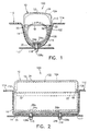
- the present invention is directed to an airbag module case 10 for use as part of a side impact airbag module 100 that mounts on the exterior of a motor vehicle seat 110 having an access opening 112 in a seat cover 114 and receiving means 116 within an internal structural member 117.
- the side impact airbag module 100 includes an airbag cushion and inflator assembly 102 having an airbag cushion 104 and an inflator 106 connected together so that inflation gas from the inflator 106 will inflate the airbag cushion 104.
- the airbag cushion and inflator assembly 102 is described generally as it relates to the instant invention. How an inflator 106 produces inflation gas and is actuated are both known in the art and, accordingly, are not described in detail as they do not in themselves constitute features of the present invention.
- the airbag module 100 also has two mounting projections comprising self-fastening studs 108a,108b extending from the airbag cushion and inflator assembly 102, generally from the inflator 106, and adapted to extend into the motor vehicle seat 110 and be secured within the receiving means 116 of the internal structural member 117 to mount the airbag module to the seat.
- the self-fastening studs 108a,108b are also not described in detail as they do not in themselves constitute features of the present invention.
- the mounting projection could be provided in a forms other than mounting studs such a flat elongated mounting flange, for example, and that the studs have securing means for engaging the receiving means 116 of the structural member 117 .
- the airbag module case according to the present invention can be adapted for use with airbag modules having other such mounting projections without departing from its true scope.
- the airbag module case 10 is comprised of a suitable material such as thermoplastic polyurethane, for example, and includes an assembly cover 12, and a first retainer arm 14 and a second retainer arm 16 that are unitary with the assembly cover 12.
- the retainer arms 14,16 are resiliently flexible.
- the assembly cover 12 is sized and shaped to substantially cover, conceal and protect any exposed portions of the airbag cushion and inflator assembly 102 of the side-impact airbag module 100 when the airbag module is mounted to the exterior of the motor vehicle seat 110.
- the assembly cover 12 is a generally rectangular box with a generally rectangular open base 18 , but could be provided in another shape, for example oval or circular, to accommodate a different airbag cushion and inflator assembly 102.
- the generally rectangular open base 18 is sized and shaped to receive the airbag cushion and inflator assembly 102 and is partly defined by a first side edge 20 and an opposed second side edge 22. (The first and second side edges 20,22 are shown as broken lines as the first and second retainer arms 14,16 are unitary with the assembly cover 12. )
- the first retainer arm 14 extends from the first side edge 20 and the second retainer arm 16 opposes the first retainer arm and extends from the second side edge 22 of the assembly cover 12. As shown, the retainer arms 14,16 are generally rectangular and elongated.
- the first retainer arm 14 defines two spaced-apart projection receiving apertures 24a,24b comprising generally circular stud-receiving holes located adjacent a distal end 26 of the first retainer arm.
- the second retainer arm 16 defines two spaced-apart projection receiving apertures 28a,28b comprising generally circular stud-receiving holes located adjacent a distal end 30 of the second retainer arm.
- the two stud-receiving holes 26a,26b of the first retainer arm 14 and the two stud-receiving holes 28a,28b of the second retainer arm 16 are spaced-apart similar to the two self-fastening studs 108a,108b extending from the airbag cushion and inflator assembly 102. As shown in FIGS.
- the opposed retainer arms 14,16 are sized and shaped to encircle and preferably tightly hug the airbag cushion and inflator assembly 102 with the distal ends 26,30 of the opposed retainer arms overlapping and positioned so that self-fastening stud 108a extending from the airbag cushion and inflator assembly 102 will extend through stud-receiving hole 28a defined by the second retainer arm 16 and stud-receiving hole 26a defined by the first retainer arm 14, and self-fastening stud 108b extending from the airbag cushion and inflator assembly will extend through stud-receiving hole 28b defined by the second retainer arm and stud-receiving hole 26b defined by the first retainer arm to secure the airbag module case 10 to the airbag module 100.
- the distal end 26 of the first retainer arm 14 overlaps the distal end 30 of the second retainer arm 16, however, the distal end of the second retainer arm could alternatively overlap the distal end of the first retainer arm.
- the airbag module case 10 also includes a tear seam 32 which is preferably located where the second retainer arm 16 meets the second side edge 22 of the assembly cover 12. Upon inflation of the airbag cushion 104, the expanding airbag cushion will cause the tear seam 32 to break open, with the assembly cover 12 pivoting out of the way about where the first retainer arm 14 meets the first side edge 20 of the assembly cover 12, so that the airbag cushion 104 can properly inflate.
- the assembly cover 12 of the airbag module case 10 is adapted to substantially cover, conceal and protect the airbag cushion and inflator assembly 102, and be positioned adjacent the seat cover 114 once the airbag module 100 is mounted to the seat 110. Since the airbag module 100 is adapted to be mounted on the exterior of the seat 110, it is important that an outer surface 34 of the assembly cover 12 be aesthetically pleasing and blend in with the seat 110 as much as possible.
- the assembly cover 12, therefore, is provided with a class A, decorative, outer surface 34 (class refers to the quality of the surface with regards to looks, texture and other factors, with class A being the best available surface quality).
- the airbag module case 10 is intended to be attached to the side-impact airbag module 100 prior to mounting the airbag module to the motor vehicle seat 110.
- the assembly cover 12 of the airbag module case 10 is first placed over the airbag cushion and inflator assembly 102, covering substantially all of the airbag cushion 104 and at least a portion of the inflator 106.
- the retainer arms 14,16 are wrapped around the remainder of the airbag cushion and inflator assembly 102 with the distal ends 26,30 of the retainer arms being pulled over the two self-fastening studs 108a,108b so that the studs can be inserted through the stud-receiving holes 24a,24b,28a,28b defined by the retainer arms.
- thermoplastic polyurethane airbag module case 10 is resiliently flexible, which allows the case 10 to fit snugly around the airbag cushion and inflator assembly 102 by allowing the retainer arms 14,16 to stretch slightly so that the studs 108a,108b can be inserted through the stud-receiving holes 24a,24b,28a,28b defined by the retainer arms and then resiliently relax back to tightly hug the airbag cushion and inflator assembly and bind against the studs so as to be retained thereon.
- the side impact airbag module 100 assembly is able to be mounted to the seat 110 by the automobile manufacturer during assembly of the automobile and not be required to be mounted by the seat manufacturer during assembly of the seat.
- the airbag module 100 is mounted to the seat 110 by simply inserting the two self- fastening studs 108a,108b through the access opening 112 in the seat cover 114 and into receiving means 116 within the seat 110.
- the present invention therefore, provides an airbag module case 10 that conceals and protects the airbag module 100, is aesthetically pleasing and blends in with the seat as much as possible, and is easily attached to the airbag module 100, independently of the seat.
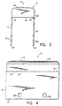
- FIGS. 5 and 6 another airbag module case 40, similar to the airbag module case 10 of FIGS. 1 through 4, is shown and includes an assembly cover 42, and a first retainer arm 44 and a second retainer arm 46 that are unitary with the assembly cover 42 .
- the assembly cover 42 is sized and shaped to substantially cover, conceal and protect any exposed portions of the airbag cushion and inflator assembly of the side-impact airbag module 100 when the airbag module is mounted to the exterior of the motor vehicle seat 110 (referring to the airbag module 100 and seat 110 of FIGS. 1 and 2 ).
- the assembly cover 42 has a generally rectangular open base 48 partly defined by a first side edge 50 and an opposed second side edge 52 .
- the first retainer arm 44 extends from the first side edge 50 and the second retainer arm 46 is opposite the first retainer arm and extends from the second side edge 52 of the assembly cover 42.
- the first retainer arm 44 defines a projection receiving aperture 54 comprising an elongated stud-receiving slot located adjacent a distal end 56 of the first retainer arm.
- the second retainer arm 46 defines a projection receiving aperture 58 comprising an elongated stud-receiving slot located adjacent a distal end 60 of the second retainer arm.
- the stud-receiving slot 54 of the first retainer arm 44 and the stud-receiving slot 58 of the second retainer arm 46 are long enough to receive both of the two self-fastening studs 108a,108b extending from the airbag module 100.
- the first and second retainer arms 44,46 are sized and shaped to encircle and preferably tightly hug the airbag cushion and inflator assembly 102 with the distal ends 56,60 of the retainer arms overlapping and positioned so that the two self-fastening studs 108a,108b extending from the airbag cushion and inflator assembly 102 will extend through the stud- receiving slot 54 defined by the first retainer arm and the stud-receiving slot 58 defined by the second retainer arm to secure the airbag module case 40 to the side-impact airbag module 100 .
- the airbag module case 40 also includes a tear seam 62 located where the second retainer arm 46 meets the second side edge 52 of the assembly cover 42.
- the assembly cover 42 is provided with a class A, decorative, outer surface 64.
- FIGS. 7 and 8 another airbag module case 70, similar to the airbag module case 10 of FIGS. 1 through 4, is shown and includes an assembly cover 72, and a first retainer arm 74, a second retainer arm 75, a third retainer arm 76 and a fourth retainer arm 77 that are unitary with the assembly cover.
- the assembly cover 72 is sized and shaped to substantially cover, conceal and protect any exposed portions of the airbag cushion and inflator assembly 102 of the side-impact airbag module 100 when the airbag module 100 is mounted to the exterior of the motor vehicle seat 110 (referring to the airbag module 100 and seat 110 of FIGS. 1 and 2 ).
- the assembly cover 72 has a generally rectangular open base 78 partly defined by a first side edge 80 and an opposed second side edge 82.
- the first retainer arm 74 and the second retainer arm extend from the first side edge 80, and the third retainer arm 76 and the fourth retainer arm 77 extend from the second side edge 82 of the assembly cover 72.
- the first retainer arm 74 defines a projection receiving aperture 84 comprising a generally circular stud-receiving hole, located adjacent a distal end 85 of the first retainer arm.
- the second retainer arm 75 defines a projection receiving aperture 85 comprising a generally circular stud-receiving hole, located adjacent a distal end 86 of the second retainer arm.
- the third retainer arm 76 defines a projection receiving aperture 88 comprising a generally circular stud-receiving hole, located adjacent a distal end 89 of the third retainer arm.
- the fourth retainer arm 77 defines a projection receiving aperture 90 comprising a generally circular stud-receiving hole, located adjacent a distal end 91 of the fourth retainer arm.
- the first retainer arm 74 and the third retainer arm 76 are opposed and are sized and shaped to encircle and preferably tightly hug the airbag cushion and inflator assembly 102 with the distal ends 85,89 overlapping and positioned so that self-fastening stud 108a extending from the airbag cushion and inflator assembly 102 will extend through the stud-receiving hole 88 defined by the third retainer arm and the stud-receiving hole 84 defined by the first retainer arm.
- the second retainer arm 75 and the fourth retainer arm 77 are opposed and are also sized and shaped to encircle and preferably tightly hug the airbag cushion and inflator assembly 102 with the distal ends 87,91 overlapping and positioned so that self-fastening stud 108b will extend through the stud-receiving hole 86 defined by the second retainer arm and the stud-receiving hole 90 defined by the fourth retainer arm to secure the airbag module case 70 to the side-impact airbag module 100.
- the airbag module case 70 also includes a first tear seam 92a located where the third retainer arm 76 meets the second side edge 80 of the assembly cover 72, and a second tear seam 92b located where the fourth retainer arm 77 meets the second side edge 82 of the assembly cover.
- the assembly cover 72 is provided with a class A, decorative, outer surface 94.
Description
Claims (13)
- A thermoplastic airbag module case (10) for use with a side impact airbag module (100) adapted to mount on the exterior of a motor vehicle seat (110) and including an airbag cushion (104) and inflator assembly (102) having a folded airbag cushion (104) and an inflator (106) connected together so that inflation gas from the inflator (106) will inflate the airbag cushion (104), the airbag module case (10) comprising:an assembly cover (12) sized and shaped to substantially cover the airbag cushion and inflator assembly (102) of the side-impact airbag module when the airbag module is mounted to the exterior of the motor vehicle seat (110), the assembly cover (12) having a decorative outer surface (34) and at least one edge (20, 22) defining an open base (18) sized and shaped to receive the airbag cushion and inflator assembly (102); andat least two flexible, opposed retainer arms (14, 16) extending from the at least one edge (20, 22) of the assembly cover (12), the opposed retainer arms (14, 16) being sized and shaped to substantially encircle the airbag cushion and inflator assembly (102) with each retainer arm (14, 16) defining at least one projection receiving aperture (24a, 24b, 28a, 28b) located adjacent a distal end (26, 30) of the retainer arm (14, 16) for receiving at least one projection (108a) extending from the airbag cushion and inflator assembly (102) to secure the airbag module case (10) to the side-impact airbag module (100).
- The airbag module case (10) according to claim 1 further comprising a tear seam (32) located where one of the at least two retainer arms (14, 16) meets the at least one edge (20, 22) of the assembly cover (12).
- The airbag module case (10) according to claim 1 or 2, wherein the at least two opposed retainer arms (14, 16) of the airbag module case (10) comprise a first retainer arm (14) extending from the at least one edge (20) of the assembly cover (12) and a second retainer arm (16) extending from the at least one edge (22) of the assembly cover (12) opposite the first retainer arm (14).
- The airbag module case (10) according to claim 3 wherein the at least one projection receiving aperture of each retainer arm (14, 16) comprises two spaced-apart, stud-receiving openings (24a, 24b; 28a, 28b) adapted to receive two spaced-apart, self-fastening studs (108a) extending from the airbag cushion and inflator assembly (102).
- The airbag module case (40) according to claim 3 wherein the at least one projection receiving aperture of each retainer arm (44, 46) comprises an elongated, stud-receiving slot (54, 58) adapted to receive two spaced-apart, self-fastening studs (108a) extending from the airbag cushion and inflator assembly (102).
- The airbag module case (70) according to claim 1 or 2 wherein the at least two opposed retainer arms of the airbag module case comprise a first and second retainer arm (74, 75) extending from the at least one edge (50) of the assembly cover (72) and a third and fourth retainer arm (76, 77) extending from the at least one edge (82) of the assembly cover (72) opposite the first and second retainer arms (74, 75), the at least one projection receiving aperture of each retainer arm (74, 75, 76, 77) comprising a stud-receiving opening (84, 86, 88, 90) adapted to receive a self-fastening stud (108a) extending from the airbag cushion and inflator assembly (102).
- The airbag module case (10) according to any one of claims 1 to 4 or claim 6 wherein the projection-receiving apertures (24a, 24b, 28a, 28b) are generally circular.
- A side-impact airbag module (100) including a module case (10) according to any preceding claim and adapted to mount on the exterior of a motor vehicle seat (110), the airbag module (100) additionally comprising:an airbag cushion and inflator assembly (102) having a folded airbag cushion (104) and an inflator (106) connected together so that inflation gas from the inflator (106) will inflate the airbag cushion (104).
- The side-impact airbag module (100) according to claim 8 wherein the opposed retainer arms (14, 16) encircle the airbag cushion and inflator assembly (102) with the distal ends (26, 30) of the opposed retainer arms (14, 16) overlapping and positioned so that at least one projection (108a) extending from the airbag cushion and inflator assembly (102) extends through the at least one projection receiving aperture (24a, 24b, 28a, 28b) of both retainer arms (14, 16).
- The side-impact airbag module (100) according to claim 8 or 9 wherein the at least one projection comprises two spaced-apart mounting projections (108a) adapted to extend into and be secured within the motor vehicle seat (110), each mounting projection (108a) comprising a self-fastening stud.
- The side-impact airbag module (100) according to claim 10 when indirectly dependent on claim 4 wherein the projection receiving apertures (24a, 24b, 28a, 28b) receive the self-fastening studs (108a).
- The side-impact airbag module (100) according to claim 10 when indirectly dependent on claim 5 wherein each stud-receiving slot (54, 58) receives both self-fastening studs (108a).
- The side-impact airbag module (100) according to claim 10 when indirectly dependent on claim 6 wherein each retainer arm (74, 75, 76, 77) defines one of the projection receiving apertures (84, 86, 88, 90) which comprises a stud-receiving opening receiving one of the self-fastening studs (108a).
Applications Claiming Priority (2)
| Application Number | Priority Date | Filing Date | Title |
|---|---|---|---|
| US08/555,210 US5568936A (en) | 1995-11-08 | 1995-11-08 | Airbag module case for side impact airbag module |
| US555210 | 1995-11-08 |
Publications (3)
| Publication Number | Publication Date |
|---|---|
| EP0773143A2 EP0773143A2 (en) | 1997-05-14 |
| EP0773143A3 EP0773143A3 (en) | 1999-03-17 |
| EP0773143B1 true EP0773143B1 (en) | 2002-02-06 |
Family
ID=24216405
Family Applications (1)
| Application Number | Title | Priority Date | Filing Date |
|---|---|---|---|
| EP96307988A Expired - Lifetime EP0773143B1 (en) | 1995-11-08 | 1996-11-05 | Airbag module case for side impact airbag module |
Country Status (4)
| Country | Link |
|---|---|
| US (1) | US5568936A (en) |
| EP (1) | EP0773143B1 (en) |
| JP (1) | JP3037542U (en) |
| DE (1) | DE69619059T2 (en) |
Families Citing this family (16)
| Publication number | Priority date | Publication date | Assignee | Title |
|---|---|---|---|---|
| JPH09142243A (en) * | 1995-11-20 | 1997-06-03 | Honda Motor Co Ltd | Air bag device for occupant protection |
| US5755457A (en) * | 1995-11-30 | 1998-05-26 | Becker Group Europe Gmbh | Air bag device |
| US5944341A (en) * | 1996-05-31 | 1999-08-31 | Nissan Motor Co., Ltd. | Air bag apparatus for vehicle |
| DE29615261U1 (en) * | 1996-09-02 | 1997-01-16 | Trw Repa Gmbh | Coverage of an airbag module integrated in a vehicle steering wheel |
| US5890733A (en) * | 1996-10-24 | 1999-04-06 | Alliedsignal Inc. | Hook and snap side air bag module attachment |
| DE19704684C2 (en) * | 1997-02-07 | 2000-08-10 | Johnson Contr Interiors Gmbh | Passenger airbag device |
| JP3590713B2 (en) * | 1997-09-19 | 2004-11-17 | 株式会社大井製作所 | Airbag device for automobile side collision |
| US6039341A (en) * | 1998-12-17 | 2000-03-21 | General Motors Corporation | Air bag module assembly |
| DE50311476D1 (en) * | 2003-05-26 | 2009-06-10 | Delphi Tech Inc | Airbag holder |
| DE202004017428U1 (en) * | 2004-11-10 | 2005-01-27 | Trw Airbag Systems Gmbh | Gas generator and gas bag module |
| US7686392B2 (en) | 2005-08-02 | 2010-03-30 | Shell Oil Company | Vehicle seat cover |
| JP4715523B2 (en) * | 2005-10-25 | 2011-07-06 | タカタ株式会社 | Crew restraint system |
| DE102006031117B4 (en) * | 2006-07-05 | 2017-07-06 | Lear Corp. | Method for assembling an airbag assembly and airbag assembly |
| DE102007060282B4 (en) * | 2007-12-12 | 2015-08-27 | Autoliv Development Ab | Curtain airbag unit and retaining element for a curtain airbag unit |
| US20110204607A1 (en) * | 2010-02-22 | 2011-08-25 | Conrad Dumbrique | Preformed flexible housing for airbag module |
| US8585078B1 (en) * | 2013-03-13 | 2013-11-19 | Autoliv Asp, Inc. | Tear seams for inflatable airbag covers |
Family Cites Families (21)
| Publication number | Priority date | Publication date | Assignee | Title |
|---|---|---|---|---|
| US3632136A (en) * | 1969-10-08 | 1972-01-04 | Eaton Yale & Towne | Safety apparatus |
| US4246213A (en) * | 1978-08-02 | 1981-01-20 | Nissan Motor Company, Limited | Method of producing a cover member for a safety air-cushion |
| GB2232936B (en) * | 1989-06-13 | 1993-07-28 | Autoliv Dev | Improvements in or relating to an arrangement for protecting an occupant of a vehicle |
| US4944527A (en) * | 1989-08-31 | 1990-07-31 | Allied-Signal Inc. | Integral retainer, heat shield and assembly |
| JP2551861B2 (en) * | 1990-10-05 | 1996-11-06 | 豊田合成株式会社 | Airbag cover |
| US5433473A (en) * | 1991-04-26 | 1995-07-18 | Toyoda Gosei Co., Ltd. | Pad mounting structure for air bag device |
| US5224732A (en) * | 1991-07-16 | 1993-07-06 | Toyota Motor Co Ltd | Inflatable restraint system for side impact crash protection |
| US5207544A (en) * | 1992-03-04 | 1993-05-04 | Vsi Corporation | Fastener assembly |
| US5326132A (en) * | 1992-08-25 | 1994-07-05 | Musiol John A | Reaction can for air bag system |
| US5303951A (en) * | 1992-10-30 | 1994-04-19 | Allied-Signal Inc. | Air bag assembly with housing and fastenerless deployment door |
| DE9216516U1 (en) * | 1992-12-04 | 1993-03-18 | Hs Technik Und Design Technische Entwicklungen Gmbh, 8000 Muenchen, De | |
| GB2273471B (en) * | 1992-12-18 | 1995-10-18 | Autoliv Dev | Improvements in or relating to an air-bag arrangement |
| DE4311241C1 (en) * | 1993-04-06 | 1994-04-28 | Daimler Benz Ag | Cover for airbag protection system - is moulded with dashboard trim and is attached to it via recessed plastics tags outside opening profile of panel |
| US5393090A (en) * | 1993-06-02 | 1995-02-28 | General Motors Corporation | Fabric housing for air bag inflator |
| US5378013A (en) * | 1993-08-06 | 1995-01-03 | Ford Motor Company | Cover retainer assembly for inflatable restraint air bag |
| US5348343A (en) * | 1993-11-01 | 1994-09-20 | General Motors Corporation | Air bag deployment bias apparatus |
| JP3366090B2 (en) * | 1993-12-17 | 2003-01-14 | 本田技研工業株式会社 | Airbag device |
| US5441299A (en) * | 1994-04-25 | 1995-08-15 | Morton International, Inc. | Air bag inflator subassembly for installation onto the dashboard substrate of a motor vehicle |
| US5468012A (en) * | 1994-06-13 | 1995-11-21 | Trw Vehicle Safety Systems Inc. | Air bag module |
| US5445409A (en) * | 1994-10-17 | 1995-08-29 | General Motors Corporation | Passenger airbag snap-on deployment door |
| US5639111A (en) * | 1995-03-29 | 1997-06-17 | General Motors Corporation | Air bag module |
-
1995
- 1995-11-08 US US08/555,210 patent/US5568936A/en not_active Expired - Lifetime
-
1996
- 1996-11-05 DE DE69619059T patent/DE69619059T2/en not_active Expired - Lifetime
- 1996-11-05 EP EP96307988A patent/EP0773143B1/en not_active Expired - Lifetime
- 1996-11-08 JP JP1996011379U patent/JP3037542U/en not_active Expired - Lifetime
Also Published As
| Publication number | Publication date |
|---|---|
| EP0773143A3 (en) | 1999-03-17 |
| EP0773143A2 (en) | 1997-05-14 |
| JP3037542U (en) | 1997-05-20 |
| US5568936A (en) | 1996-10-29 |
| DE69619059T2 (en) | 2002-09-05 |
| DE69619059D1 (en) | 2002-03-21 |
Similar Documents
| Publication | Publication Date | Title |
|---|---|---|
| US5533746A (en) | Tethered cover for a panel opening in an air bag inflator system | |
| EP0773143B1 (en) | Airbag module case for side impact airbag module | |
| US5799970A (en) | Externally mounted side airbag module with decorative outer cover | |
| EP0761509B1 (en) | Exterior seat back mounted side impact airbag module assembly | |
| EP1510420B1 (en) | Occupant protection system | |
| US5498030A (en) | Air bag module | |
| US5951039A (en) | Side airbag closeout assembly for vehicular seats and method of installation | |
| KR100500101B1 (en) | Side airbag curtain module | |
| US5556127A (en) | Seat mounted side impact module | |
| US5667241A (en) | Seat mounted side impact airbags | |
| US6089659A (en) | Headrest secured automobile seat cover | |
| US7185912B2 (en) | Knee protection airbag device | |
| US5676394A (en) | Seat trim deployment cover for side airbag module | |
| US5890734A (en) | Integral cover-deployment chute for side airbag module | |
| US5540460A (en) | Air bag module | |
| JPH10297414A (en) | Vehicle seat provided with side air bag | |
| US5529332A (en) | Air bag module | |
| JP3411524B2 (en) | Automotive side airbag device | |
| JP4653885B2 (en) | Airbag device | |
| JPH03227753A (en) | Air bag system of car | |
| JPH1159312A (en) | Occupant crash protection device | |
| JP4176553B2 (en) | Airbag device for side impact of automobile | |
| JPH1134782A (en) | Air bag device for front passenger seat | |
| JP3976928B2 (en) | Airbag structure | |
| JP2894430B2 (en) | Airbag device |
Legal Events
| Date | Code | Title | Description |
|---|---|---|---|
| PUAI | Public reference made under article 153(3) epc to a published international application that has entered the european phase |
Free format text: ORIGINAL CODE: 0009012 |
|
| AK | Designated contracting states |
Kind code of ref document: A2 Designated state(s): DE FR GB IT |
|
| PUAL | Search report despatched |
Free format text: ORIGINAL CODE: 0009013 |
|
| 17P | Request for examination filed |
Effective date: 19981203 |
|
| AK | Designated contracting states |
Kind code of ref document: A3 Designated state(s): DE FR GB IT |
|
| 17Q | First examination report despatched |
Effective date: 20000202 |
|
| GRAG | Despatch of communication of intention to grant |
Free format text: ORIGINAL CODE: EPIDOS AGRA |
|
| GRAG | Despatch of communication of intention to grant |
Free format text: ORIGINAL CODE: EPIDOS AGRA |
|
| GRAG | Despatch of communication of intention to grant |
Free format text: ORIGINAL CODE: EPIDOS AGRA |
|
| GRAH | Despatch of communication of intention to grant a patent |
Free format text: ORIGINAL CODE: EPIDOS IGRA |
|
| GRAH | Despatch of communication of intention to grant a patent |
Free format text: ORIGINAL CODE: EPIDOS IGRA |
|
| RAP1 | Party data changed (applicant data changed or rights of an application transferred) |
Owner name: AUTOLIV ASP, INC. |
|
| GRAA | (expected) grant |
Free format text: ORIGINAL CODE: 0009210 |
|
| REG | Reference to a national code |
Ref country code: GB Ref legal event code: IF02 |
|
| AK | Designated contracting states |
Kind code of ref document: B1 Designated state(s): DE FR GB IT |
|
| PG25 | Lapsed in a contracting state [announced via postgrant information from national office to epo] |
Ref country code: IT Free format text: LAPSE BECAUSE OF FAILURE TO SUBMIT A TRANSLATION OF THE DESCRIPTION OR TO PAY THE FEE WITHIN THE PRESCRIBED TIME-LIMIT;WARNING: LAPSES OF ITALIAN PATENTS WITH EFFECTIVE DATE BEFORE 2007 MAY HAVE OCCURRED AT ANY TIME BEFORE 2007. THE CORRECT EFFECTIVE DATE MAY BE DIFFERENT FROM THE ONE RECORDED. Effective date: 20020206 |
|
| REF | Corresponds to: |
Ref document number: 69619059 Country of ref document: DE Date of ref document: 20020321 |
|
| ET | Fr: translation filed | ||
| PLBE | No opposition filed within time limit |
Free format text: ORIGINAL CODE: 0009261 |
|
| STAA | Information on the status of an ep patent application or granted ep patent |
Free format text: STATUS: NO OPPOSITION FILED WITHIN TIME LIMIT |
|
| 26N | No opposition filed |
Effective date: 20021107 |
|
| PGFP | Annual fee paid to national office [announced via postgrant information from national office to epo] |
Ref country code: GB Payment date: 20031029 Year of fee payment: 8 |
|
| PG25 | Lapsed in a contracting state [announced via postgrant information from national office to epo] |
Ref country code: GB Free format text: LAPSE BECAUSE OF NON-PAYMENT OF DUE FEES Effective date: 20041105 |
|
| GBPC | Gb: european patent ceased through non-payment of renewal fee |
Effective date: 20041105 |
|
| PGFP | Annual fee paid to national office [announced via postgrant information from national office to epo] |
Ref country code: FR Payment date: 20070919 Year of fee payment: 12 |
|
| REG | Reference to a national code |
Ref country code: FR Ref legal event code: ST Effective date: 20090731 |
|
| PGFP | Annual fee paid to national office [announced via postgrant information from national office to epo] |
Ref country code: DE Payment date: 20090915 Year of fee payment: 14 |
|
| REG | Reference to a national code |
Ref country code: DE Ref legal event code: R119 Ref document number: 69619059 Country of ref document: DE Effective date: 20110601 Ref country code: DE Ref legal event code: R119 Ref document number: 69619059 Country of ref document: DE Effective date: 20110531 |
|
| PG25 | Lapsed in a contracting state [announced via postgrant information from national office to epo] |
Ref country code: DE Free format text: LAPSE BECAUSE OF NON-PAYMENT OF DUE FEES Effective date: 20110531 Ref country code: FR Free format text: LAPSE BECAUSE OF NON-PAYMENT OF DUE FEES Effective date: 20081130 |