EP0772967A1 - Mäh- und Konditionierungsvorrichtung - Google Patents
Mäh- und Konditionierungsvorrichtung Download PDFInfo
- Publication number
- EP0772967A1 EP0772967A1 EP96203061A EP96203061A EP0772967A1 EP 0772967 A1 EP0772967 A1 EP 0772967A1 EP 96203061 A EP96203061 A EP 96203061A EP 96203061 A EP96203061 A EP 96203061A EP 0772967 A1 EP0772967 A1 EP 0772967A1
- Authority
- EP
- European Patent Office
- Prior art keywords
- crushing
- mowing
- crushing member
- adjusting means
- machine
- Prior art date
- Legal status (The legal status is an assumption and is not a legal conclusion. Google has not performed a legal analysis and makes no representation as to the accuracy of the status listed.)
- Granted
Links
Images


Classifications
-
- A—HUMAN NECESSITIES
- A01—AGRICULTURE; FORESTRY; ANIMAL HUSBANDRY; HUNTING; TRAPPING; FISHING
- A01D—HARVESTING; MOWING
- A01D43/00—Mowers combined with apparatus performing additional operations while mowing
- A01D43/10—Mowers combined with apparatus performing additional operations while mowing with means for crushing or bruising the mown crop
- A01D43/102—Bruising control devices
-
- Y—GENERAL TAGGING OF NEW TECHNOLOGICAL DEVELOPMENTS; GENERAL TAGGING OF CROSS-SECTIONAL TECHNOLOGIES SPANNING OVER SEVERAL SECTIONS OF THE IPC; TECHNICAL SUBJECTS COVERED BY FORMER USPC CROSS-REFERENCE ART COLLECTIONS [XRACs] AND DIGESTS
- Y10—TECHNICAL SUBJECTS COVERED BY FORMER USPC
- Y10S—TECHNICAL SUBJECTS COVERED BY FORMER USPC CROSS-REFERENCE ART COLLECTIONS [XRACs] AND DIGESTS
- Y10S56/00—Harvesters
- Y10S56/15—Condition responsive
Definitions
- the present invention relates to a mowing machine comprising a mowing unit and a crushing member, as well as adjusting means, by means of which one or more crushing characteristics can be adjusted.
- Such a mowing machine is known from e.g. DE-A1-43 01 821.
- the thickness and/or the length and/or the quantity and/or the type of the crop to be crushed in a mowing machine varies.
- the flow of crop towards the crushing member will increase, which may entail that the crop is wound around the crushing member and/or is insufficiently treated by the crushing elements, while there is a reasonable risk that the crushing member gets blocked.
- the extent to which the crushing member is loaded during operation thereby increases. From the aforementioned document there is known a construction in which, in order to obviate this drawback, the mutual position of the crushing member and the mowing unit is adjustable.
- the crushing characteristics of the machine are adjusted so as to be attuned to the conditions adapted to the crop, nevertheless, during operation, the problem may occur that the crushing member gets blocked and consequently gets overloaded.
- the adjustment may have been assessed wrongly or the quantity of crop may be different in various parts of the plot to be treated.
- the latter in accordance with the invention, is characterized in that there is available at least one sensor, by means of which the extent to which the crushing member is loaded during operation is recorded, which sensor supplies one or more control signals to the above-mentioned adjusting means for the automatic adjustment of the above-mentioned crushing characteristics.
- the crushing characteristics of the crushing member and the mowing unit are automatically adjusted depending on the extent to which the crushing member is loaded.
- the adjusting means for adjusting these crushing characteristics can be suitable for adjusting the mutual position of the crushing member and the mowing unit and/or for varying the number of revolutions of the crushing member and/or for adjusting the size of the crop channel, etc.
- the crushing characteristics can relate to the relative position, in particular the distance, between the crushing member and the mowing unit, as well as to the intensity of the crushing proper, in particular by means of the number of revolutions of the crushing member and the size of the crop channel.
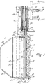
- the mowing machine 1 shown in the figures, comprises a mowing unit 2 and a crushing member 3 including a rotor 4 and crushing elements 5, as well as an element 7 constituting together with said crushing member 3 a crop channel 6.
- the mowing unit 2 is composed of a cutter bar 8 including six mowing discs 9 provided with mowing knives 10, pivotable thereabove about vertical shafts. Above the cutter bar 8 and parallel thereto, there is disposed a carrier beam 11.
- the connection between the cutter bar 8 and the carrier beam 11 is constituted at one end by a gear box 12 and at the other end by a supporting element 13, extending obliquely rearwards and downwards from the carrier beam 11, and a substantially horizontally extending connecting element 14, connected with said supporting element near the lower end thereof and also connected with the cutter bar 8.
- the mowing machine is pivotably connected, in a customary manner, about an approximately horizontal pivot shaft 15, which, in its operative position, extends in the direction of travel, with a supporting arm 16 including a carrier frame 17, by means of which the mowing machine can be coupled to a three-point lifting hitch of a tractor or similar.
- the drive of the mowing machine takes place from a power take-off shaft 18 of a (non-shown) tractor, via different transmission members in a gear box 12, connected with the supporting arm 16, from which the mowing unit 2 is driven by means of a belt transmission 19 and the different transmission members in the gear box 12, and the crushing member 3 is driven by means of an intermediary shaft 21 provided with universal joints 20.
- the outer mowing disc at the side where the elements 13 and 14 constitute the connection between the cutter bar 8 and the carrier beam 11, is provided with a hat-shaped crop guide member 22.
- the crushing member 3 is pivotably disposed between the angle plates 26.
- To the frame 23 there are additionally fastened top plate elements 27 and side plate elements 28 and 29, whereby the rearmost side plate elements 29 extend inwardly in rearward direction and are outwardly bent at their lower sides.
- a first support 33 and a second support 34 are fixed to the supporting beams 24.
- a connecting strip 35, pivotable in the second support 34 can be fixed in the first support 33 in such a way that the position of this connecting element 35, and consequently that of the strip 38 fixed thereto including the beater bar 39 fixed to said strip, extending in the longitudinal direction of the crushing member 3, determine the required size of the crop channel 6.
- the rotor 4 of the crushing member 3 comprises a cylindrical carrier 40, on which the crushing elements 5 are disposed so as to be staggered relative to each other.
- the crushing elements 5 are tapering, have an I-shaped profile and project outwardly from the roller.
- the outer crushing elements 41 on both sides of the cylindrical roller 40 are flat, tapering and also project outwardly from the roller.
- the outer crushing elements are dagger-shaped and are preferably made of a flat strip of spring steel having a thickness of approximately 3 mm. Seen in plan view, the outer crushing elements 41 are located at a distance of approximately one cm from the side plate elements 28.
- the dagger-shaped outer flat crushing elements 41 move relatively close along the side plate elements 28, material to be crushed, that has settled on said side plate elements 28 or has gathered in the angles of the crop channel 6, is cut up. As the crop cut up is wound less easily and can be better discharged, it is avoided that the rotor 4 runs roughly and the crop channel 6 and possibly the rotor 4 are blocked up with crop.
- the application of a relatively thin strip of spring steel for the outer crushing elements 41 has the advantage that the crushing elements 41, seen in the direction of rotation of the rotor 4, are relatively stiff, while the crushing elements 41, in a direction perpendicular to the direction of rotation of the rotor 4, on the contrary, can easily deflect and spring back.
- the latter phenomenon may occur when, for example, undesired objects, such as a piece of wood or a stone, get into the rotor 4.
- more than two dragger-shaped crushing elements 41 can be disposed on the cylindrical carrier 40, and that the crushing elements 41 can be made of an other material, having characteristics identical to those of spring steel, such as synthetic material.
- the frame 23, in which the crushing member 3 is pivotably suspended, can be moved relative to the cutter bar 8.
- the two supporting beams 24 comprise near their front side a guide means 42, and the mowing unit 2 can reciprocate in said guide means 42 by means of supports 43, provided at the ends of the carrier beam 11, and rollers 44 fastened thereto.
- This reciprocating movement can be achieved by means of adjusting means, in particular a control cylinder 45, fastened to a supporting beam 24, at one or both sides of the machine.
- the crushing member 4 is provided with a sensor 50, by means of which the extent to which the crushing member is loaded is determined by the flow of crop conducted through.
- the control cylinders 45, 49 respectively, shown in both embodiments, are controlled from said sensor 50, by means of a control signal supplied by same.
- the crushing member 3 is loaded to a greater extent than at a relatively small flow of crop, while the distance between the mowing unit 2 and the crushing member 3 will have to be greater.
- This sensor 50 and the control cylinders 45, 49 respectively controlled thereby there is obtained an automatic adjustment of the distance between the mowing unit 2 and the crushing member 3.
- the sensor 50 can be constituted by various types of sensors; there can be used force meters i.e.
- the crushing characteristics of the machine can also be adjusted by the application of adjusting means suitable for adjusting the crushing intensity. It is possible, for example, to adjust the crushing intensity by means of a unit for varying the number of revolutions of the crushing member. Depending on the crop conditions, at a specific number of revolutions, it will be possible to obtain an optimal crushing of the crop. Of course, the latter unit will then be controlled by control signals supplied by the sensor 50.
- the adjusting means are constituted by a unit for adjusting the size of the crop channel. Actually, in the above described embodiment, this can be achieved by the automatic adjustment of the strip 38 including the beater bar 39.
Landscapes
- Life Sciences & Earth Sciences (AREA)
- Environmental Sciences (AREA)
- Harvester Elements (AREA)
Applications Claiming Priority (2)
| Application Number | Priority Date | Filing Date | Title |
|---|---|---|---|
| NL1001586A NL1001586C2 (nl) | 1995-11-07 | 1995-11-07 | Maaimachine. |
| NL1001586 | 1995-11-07 |
Publications (2)
| Publication Number | Publication Date |
|---|---|
| EP0772967A1 true EP0772967A1 (de) | 1997-05-14 |
| EP0772967B1 EP0772967B1 (de) | 2000-05-03 |
Family
ID=19761814
Family Applications (1)
| Application Number | Title | Priority Date | Filing Date |
|---|---|---|---|
| EP96203061A Expired - Lifetime EP0772967B1 (de) | 1995-11-07 | 1996-11-04 | Mäh- und Konditionierungsvorrichtung |
Country Status (5)
| Country | Link |
|---|---|
| US (1) | US5845469A (de) |
| EP (1) | EP0772967B1 (de) |
| AU (1) | AU709053B2 (de) |
| DE (1) | DE69608070T2 (de) |
| NL (1) | NL1001586C2 (de) |
Cited By (5)
| Publication number | Priority date | Publication date | Assignee | Title |
|---|---|---|---|---|
| WO1998004112A2 (en) * | 1996-07-29 | 1998-02-05 | Maasland N.V. | A mowing machine |
| EP0835603A2 (de) * | 1996-08-14 | 1998-04-15 | Alois Pöttinger Maschinenfabrik GmbH | Aufbereitungseinrichtung mit elektronischer Regeleinrichtung für eine landwirtschaftliche Bearbeitungsmaschine |
| EP0965260A1 (de) * | 1998-06-18 | 1999-12-22 | NIEMEYER Landmaschinen GmbH | Aufbereiter für Kreiselmäher |
| NL1009562C2 (nl) * | 1998-07-06 | 2000-01-10 | Maasland Nv | Maaimachine. |
| EP2436259A1 (de) * | 2010-10-01 | 2012-04-04 | CLAAS Saulgau GmbH | Aufbereitungseinrichtung mit elektronischer Steuereinrichtung für eine landwirtschaftliche Arbeitsmaschine |
Families Citing this family (4)
| Publication number | Priority date | Publication date | Assignee | Title |
|---|---|---|---|---|
| NL1006826C2 (nl) * | 1997-08-22 | 1999-02-23 | Maasland Nv | Landbouwmachine en werkwijze voor het gebruik daarvan. |
| NL1011885C2 (nl) * | 1999-04-23 | 2000-10-24 | Lely Res Holding | Landbouwmachine. |
| US6431981B1 (en) * | 1999-06-30 | 2002-08-13 | Wisconsin Alumni Research Foundation | Yield monitor for forage crops |
| US10653061B2 (en) | 2015-07-07 | 2020-05-19 | Deere & Company | Method and apparatus for harvesting crop material |
Citations (6)
| Publication number | Priority date | Publication date | Assignee | Title |
|---|---|---|---|---|
| FR2328386A1 (fr) * | 1975-10-23 | 1977-05-20 | Clayson Nv | Faucheuse-conditionneuse |
| EP0155063A2 (de) * | 1984-03-15 | 1985-09-18 | C. van der Lely N.V. | Mähmaschine |
| NL8701155A (nl) * | 1987-05-14 | 1988-12-01 | Lely Nv C Van Der | Kneusinrichting en maaiinrichting voorzien van kneusinrichting. |
| WO1990012492A1 (de) * | 1989-04-15 | 1990-11-01 | Allwoerden Wilhelm Von | Verfahren und vorrichtung der grünfutteraufbereitung |
| DE4301821A1 (de) | 1993-01-23 | 1994-08-11 | Krone Bernhard Gmbh Maschf | Mähmaschine mit einer dieser nachgeordneten Konditionierungsvorrichtung |
| EP0682859A2 (de) * | 1994-05-19 | 1995-11-22 | Maasland N.V. | Mähmaschine |
Family Cites Families (8)
| Publication number | Priority date | Publication date | Assignee | Title |
|---|---|---|---|---|
| US3673779A (en) * | 1970-04-23 | 1972-07-04 | Int Harvester Co | Harvesting machine |
| US3659403A (en) * | 1970-06-01 | 1972-05-02 | Allis Chalmers Mfg Co | Floating feeder beater |
| FR2403012A1 (fr) * | 1977-09-16 | 1979-04-13 | Samibem Sa | Perfectionnement aux faucheuses-conditionneuses |
| US4233803A (en) * | 1978-05-04 | 1980-11-18 | Deere & Company | Adjustable conditioning plate for an impeller mower-conditioner |
| GB2076273B (en) * | 1980-04-22 | 1983-11-30 | Massey Ferguson Perkins Ltd | Mower-conditioner |
| DE3528372A1 (de) * | 1985-08-07 | 1987-02-12 | Kloeckner Humboldt Deutz Ag | Vorrichtung zum maehen und aufbereiten von halmgut |
| US4803830A (en) * | 1987-08-19 | 1989-02-14 | Deere & Company | Support arrangement for cotton harvester row units |
| US4896492A (en) * | 1988-09-23 | 1990-01-30 | Deere & Company | Row unit support mechanism for transverse movement |
-
1995
- 1995-11-07 NL NL1001586A patent/NL1001586C2/nl not_active IP Right Cessation
-
1996
- 1996-11-04 EP EP96203061A patent/EP0772967B1/de not_active Expired - Lifetime
- 1996-11-04 DE DE69608070T patent/DE69608070T2/de not_active Expired - Lifetime
- 1996-11-04 US US08/744,071 patent/US5845469A/en not_active Expired - Lifetime
- 1996-11-07 AU AU70633/96A patent/AU709053B2/en not_active Ceased
Patent Citations (6)
| Publication number | Priority date | Publication date | Assignee | Title |
|---|---|---|---|---|
| FR2328386A1 (fr) * | 1975-10-23 | 1977-05-20 | Clayson Nv | Faucheuse-conditionneuse |
| EP0155063A2 (de) * | 1984-03-15 | 1985-09-18 | C. van der Lely N.V. | Mähmaschine |
| NL8701155A (nl) * | 1987-05-14 | 1988-12-01 | Lely Nv C Van Der | Kneusinrichting en maaiinrichting voorzien van kneusinrichting. |
| WO1990012492A1 (de) * | 1989-04-15 | 1990-11-01 | Allwoerden Wilhelm Von | Verfahren und vorrichtung der grünfutteraufbereitung |
| DE4301821A1 (de) | 1993-01-23 | 1994-08-11 | Krone Bernhard Gmbh Maschf | Mähmaschine mit einer dieser nachgeordneten Konditionierungsvorrichtung |
| EP0682859A2 (de) * | 1994-05-19 | 1995-11-22 | Maasland N.V. | Mähmaschine |
Cited By (10)
| Publication number | Priority date | Publication date | Assignee | Title |
|---|---|---|---|---|
| WO1998004112A2 (en) * | 1996-07-29 | 1998-02-05 | Maasland N.V. | A mowing machine |
| WO1998004112A3 (en) * | 1996-07-29 | 1998-03-19 | Maasland Nv | A mowing machine |
| EP1155608A2 (de) * | 1996-07-29 | 2001-11-21 | Maasland N.V. | Mähmaschine |
| EP1155608A3 (de) * | 1996-07-29 | 2002-09-11 | Maasland N.V. | Mähmaschine |
| EP0835603A2 (de) * | 1996-08-14 | 1998-04-15 | Alois Pöttinger Maschinenfabrik GmbH | Aufbereitungseinrichtung mit elektronischer Regeleinrichtung für eine landwirtschaftliche Bearbeitungsmaschine |
| EP0835603A3 (de) * | 1996-08-14 | 1998-04-22 | Alois Pöttinger Maschinenfabrik GmbH | Aufbereitungseinrichtung mit elektronischer Regeleinrichtung für eine landwirtschaftliche Bearbeitungsmaschine |
| EP0965260A1 (de) * | 1998-06-18 | 1999-12-22 | NIEMEYER Landmaschinen GmbH | Aufbereiter für Kreiselmäher |
| NL1009562C2 (nl) * | 1998-07-06 | 2000-01-10 | Maasland Nv | Maaimachine. |
| EP0970597A1 (de) * | 1998-07-06 | 2000-01-12 | Maasland N.V. | Mäh- und Konditionierungsvorrichtung |
| EP2436259A1 (de) * | 2010-10-01 | 2012-04-04 | CLAAS Saulgau GmbH | Aufbereitungseinrichtung mit elektronischer Steuereinrichtung für eine landwirtschaftliche Arbeitsmaschine |
Also Published As
| Publication number | Publication date |
|---|---|
| AU709053B2 (en) | 1999-08-19 |
| DE69608070T2 (de) | 2000-12-21 |
| EP0772967B1 (de) | 2000-05-03 |
| AU7063396A (en) | 1997-05-15 |
| DE69608070D1 (de) | 2000-06-08 |
| NL1001586C2 (nl) | 1997-05-13 |
| US5845469A (en) | 1998-12-08 |
Similar Documents
| Publication | Publication Date | Title |
|---|---|---|
| DE4419421C2 (de) | Verteilvorrichtung für Häcksler | |
| EP0772967B1 (de) | Mäh- und Konditionierungsvorrichtung | |
| US6421994B1 (en) | Mowing implement | |
| EP3912454A1 (de) | Rollenkonditioniererverstellsystem für eine landwirtschaftliche erntemaschine | |
| CA1233647A (en) | Snow trap attachment for crop harvesting machine | |
| AU620392B2 (en) | A mowing machine | |
| EP0970597A1 (de) | Mäh- und Konditionierungsvorrichtung | |
| US11096329B2 (en) | Crop conditioner hood with integrated swathboard | |
| EP1029437B1 (de) | Mäh- und Konditioniervorrichtung | |
| EP0861020B1 (de) | Mähmaschine | |
| DE19627872A1 (de) | Einrichtung zum Häckseln von Pflanzen | |
| US3355865A (en) | Forage harvester | |
| AU756453B2 (en) | A mowing machine | |
| US4236372A (en) | Agricultural harvesting machines with crop pick-up mechanisms | |
| US3422606A (en) | Crop conditioner attachment for a windrower | |
| EP0740898A2 (de) | Apparat zur Behandlung von Erntegut mit Faltgestell | |
| EP0189957A2 (de) | Bodenbearbeitungsgeräte | |
| NZ335273A (en) | Mowing machine with interconnected cutter bar and motor driven wheel for minimising need for course correction by tractor driver | |
| IE900873L (en) | Fodder distribution device | |
| JPH0442992Y2 (de) | ||
| CA1114621A (en) | Horizontally rotating blade-type conditioning device for swathers | |
| GB2093685A (en) | Forage harvesters | |
| AU8889198A (en) | An agricultural machine and a method of using same | |
| GB1578386A (en) | Harvesting machine | |
| NL8103282A (nl) | Hooimachine. |
Legal Events
| Date | Code | Title | Description |
|---|---|---|---|
| PUAI | Public reference made under article 153(3) epc to a published international application that has entered the european phase |
Free format text: ORIGINAL CODE: 0009012 |
|
| AK | Designated contracting states |
Kind code of ref document: A1 Designated state(s): DE FR GB NL |
|
| 17P | Request for examination filed |
Effective date: 19971103 |
|
| GRAG | Despatch of communication of intention to grant |
Free format text: ORIGINAL CODE: EPIDOS AGRA |
|
| 17Q | First examination report despatched |
Effective date: 19990817 |
|
| GRAG | Despatch of communication of intention to grant |
Free format text: ORIGINAL CODE: EPIDOS AGRA |
|
| GRAH | Despatch of communication of intention to grant a patent |
Free format text: ORIGINAL CODE: EPIDOS IGRA |
|
| GRAH | Despatch of communication of intention to grant a patent |
Free format text: ORIGINAL CODE: EPIDOS IGRA |
|
| GRAA | (expected) grant |
Free format text: ORIGINAL CODE: 0009210 |
|
| AK | Designated contracting states |
Kind code of ref document: B1 Designated state(s): DE FR GB NL |
|
| REF | Corresponds to: |
Ref document number: 69608070 Country of ref document: DE Date of ref document: 20000608 |
|
| ET | Fr: translation filed | ||
| PLBE | No opposition filed within time limit |
Free format text: ORIGINAL CODE: 0009261 |
|
| STAA | Information on the status of an ep patent application or granted ep patent |
Free format text: STATUS: NO OPPOSITION FILED WITHIN TIME LIMIT |
|
| 26N | No opposition filed | ||
| REG | Reference to a national code |
Ref country code: GB Ref legal event code: IF02 |
|
| PGFP | Annual fee paid to national office [announced via postgrant information from national office to epo] |
Ref country code: GB Payment date: 20021030 Year of fee payment: 7 |
|
| PGFP | Annual fee paid to national office [announced via postgrant information from national office to epo] |
Ref country code: NL Payment date: 20031022 Year of fee payment: 8 |
|
| PG25 | Lapsed in a contracting state [announced via postgrant information from national office to epo] |
Ref country code: GB Free format text: LAPSE BECAUSE OF NON-PAYMENT OF DUE FEES Effective date: 20031104 |
|
| GBPC | Gb: european patent ceased through non-payment of renewal fee |
Effective date: 20031104 |
|
| PG25 | Lapsed in a contracting state [announced via postgrant information from national office to epo] |
Ref country code: NL Free format text: LAPSE BECAUSE OF NON-PAYMENT OF DUE FEES Effective date: 20050601 |
|
| NLV4 | Nl: lapsed or anulled due to non-payment of the annual fee |
Effective date: 20050601 |
|
| PGFP | Annual fee paid to national office [announced via postgrant information from national office to epo] |
Ref country code: DE Payment date: 20141128 Year of fee payment: 19 Ref country code: FR Payment date: 20141118 Year of fee payment: 19 |
|
| REG | Reference to a national code |
Ref country code: DE Ref legal event code: R119 Ref document number: 69608070 Country of ref document: DE |
|
| REG | Reference to a national code |
Ref country code: FR Ref legal event code: ST Effective date: 20160729 |
|
| PG25 | Lapsed in a contracting state [announced via postgrant information from national office to epo] |
Ref country code: DE Free format text: LAPSE BECAUSE OF NON-PAYMENT OF DUE FEES Effective date: 20160601 |
|
| PG25 | Lapsed in a contracting state [announced via postgrant information from national office to epo] |
Ref country code: FR Free format text: LAPSE BECAUSE OF NON-PAYMENT OF DUE FEES Effective date: 20151130 |