EP0772271B1 - Kabelkanal - Google Patents
Kabelkanal Download PDFInfo
- Publication number
- EP0772271B1 EP0772271B1 EP96650049A EP96650049A EP0772271B1 EP 0772271 B1 EP0772271 B1 EP 0772271B1 EP 96650049 A EP96650049 A EP 96650049A EP 96650049 A EP96650049 A EP 96650049A EP 0772271 B1 EP0772271 B1 EP 0772271B1
- Authority
- EP
- European Patent Office
- Prior art keywords
- duct
- ducts
- cable duct
- cover
- finger
- Prior art date
- Legal status (The legal status is an assumption and is not a legal conclusion. Google has not performed a legal analysis and makes no representation as to the accuracy of the status listed.)
- Expired - Lifetime
Links
Images


Classifications
-
- H—ELECTRICITY
- H02—GENERATION; CONVERSION OR DISTRIBUTION OF ELECTRIC POWER
- H02G—INSTALLATION OF ELECTRIC CABLES OR LINES, OR OF COMBINED OPTICAL AND ELECTRIC CABLES OR LINES
- H02G3/00—Installations of electric cables or lines or protective tubing therefor in or on buildings, equivalent structures or vehicles
- H02G3/02—Details
- H02G3/06—Joints for connecting lengths of protective tubing or channels, to each other or to casings, e.g. to distribution boxes; Ensuring electrical continuity in the joint
- H02G3/0608—Joints for connecting non cylindrical conduits, e.g. channels
Definitions
- This invention relates to a cable duct.
- the invention particularly relates to a cable duct for use in the installation of track-side signalling, fibre optic and telecommunications cable systems for railway and light railway projects.
- DE-U7015776 discloses a rail element for guiding and mounting a cable clip.
- Cable ducts in precast concrete material are widely used for housing cabling alongside railway tracks.
- the inherent weight of concrete ducts makes them relatively difficult and cumbersome to handle and time consuming to lay.
- the present invention is directed towards overcoming this problem and providing an improved cable duct.
- a cable duct having a base with upstanding side walls at opposite sides of the base forming with the base an open ended channel for reception of cables, and means at each end of the duct for interlocking the duct with another duct end to end to form an extended channel for cables or the like, expansion means being provided to facilitate longitudinal expansion of adjacent ducts when interlocked end to end, the expansion means including complimentary inter-engagable formations at each end of the duct, the associated formations on a pair of ducts overlapping upon interlocking of said pair of ducts to prevent ingress of material into the ducts.
- the duct is formed of a structural foam plastics materials resulting in a light weight duct of good strength.
- the duct can be laid in a relatively easy and rapid fashion.
- means is provided to prevent relative vertical movement between a pair of interlocked ducts.
- said means comprises complementary interengagable formations at each end of the duct which engage when a pair of ducts are interlocked.
- the expansion means comprises at each end of the duct a curved flange on one side wall and an associated curved housing on the other side wall, the flange of one duct being rotatable engagable within the housing on an adjacent duct when interlocking the ducts.
- mounting means is provided on the duct for mounting the duct on one or more support posts.
- the mounting means comprises one or more post-engaging sockets on the duct.
- each socket is vertically disposed on a side wall of the duct having a downwardly open inlet.
- an outwardly extending shoe is provided at a lower end of each side wall for keying the duct into a foundation material.
- an upper face of the shoe slopes upwardly and outwardly from the side wall.
- a number of spaced-apart upstanding ribs are provided extending outwardly from each side wall and upwardly from the shoe.
- the duct interlocking means is releasably inter-engagable with a complementary interlocking means on another duct.
- the interlocking means comprises a curved finger at each end of the duct, each finger for hooking engagement with a complementary finger on another duct.
- means is provided to prevent relative vertical movement between a pair of interlocked ducts.
- said means comprises a tongue associated with each finger, the tongue spaced-apart from the finger and vertically displaced relative to the finger so that when a pair of fingers interlock a tongue associated with one of the fingers engages beneath the other finger.
- the duct interlocking means is of two-part construction comprising a male connector which is releasably engagable with a complimentary female receiver, one of said parts being provided at each end of the duct.
- the male part comprises a bulbus head connected to the base by a narrow neck and the female receiver comprises a re-entrant slot in the base.
- the means to prevent relative vertical movement between a pair of interlocked ducts comprises complimentary inter-engagable formations on the male and female parts.
- a number of spaced-apart upstanding ribs are provided extending outwardly from each side wall and upwardly from the shoe. These ribs advantageously provide strengthening and also assist in the positive location of the duct within a foundation material resisting movement of the duct within the foundation material.
- the side walls are of hollow construction comprising inner and outer walls interconnected by internal ribs.
- the ribs strengthen the side walls and also facilitate the flow of plastics material in a mould when forming the duct.
- hanger means is provided on the duct for suspending the duct on a wall, embankment or the like.
- the duct has a number of spaced-apart knock-out panels, each panel being removable for through passage of cables into or out of the duct.
- the base has a water drain channel in a top surface of the base.
- the water drain channel extends between opposite ends of the base.
- a shoulder is formed at a top end of each side wall for reception of a cover engagable between the side walls to close the duct.
- the shoulder has an outwardly and downwardly sloping upper surface to facilitate water run-off.
- a hinge mount is formed at an upper end of one or both side walls for hingedly mounting the cover on the side walls.
- the hinge mount is integrally formed with the post mounting means.
- the cover has a top with a downwardly depending peripheral rim and ribs on an underside of the top located within the rim.
- a top surface of the cover has an anti-slip surface.
- the anti-slip surface is preferably formed by a plurality of upstanding spaced-apart projections on the top surface.
- one or more water drainage slots are provided at an edge of the top surface.
- one or more hinge pins are provided at an edge of the cover for engagement with the hinge mount on the duct.
- locking means may be provided for releasably securing the cover on the duct.
- the expansion means comprises complimentary inter-engagable formations at each end of the duct, the formations projecting outwardly of at least one end of the duct so that the associated formations on a pair of ducts overlap upon interlocking of said ducts to prevent ingress of material into the ducts, the cover for the duct also being provided with overlapping expansion formations at each end of the cover for overlapping engagement with adjacent covers.
- the invention provides an interlocking device for ducts as herein described.
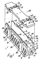
- a cable duct according to the invention indicated generally by the reference numeral 1.
- the duct 1 is formed from plastics material using a structural foam injection moulding process which incorporates injecting nitrogen gas into the melt at the moulding stage. This results in an aerated bubble/honeycomb structure in the wall section which combines light weight and high strength in the duct.
- the duct 1 has a base 2 with upstanding side walls 3 at opposite sides of the base 2 forming with the base 2 an open ended channel for reception of cables.
- a duct interlocking device 5 is provided at each end of the duct 1 at the base 2 for interlocking the duct 1 with another duct 1 end to end to form an extended channel for cables.
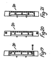
- the interlocking device 5 comprises a curved finger 6, each finger 6 for hooking engagement with a complementary finger 6 on another duct 1 as shown in Fig. 2.
- a curved slot 7 behind each finger 6 receives another finger 6 for hooking engagement of the fingers 6 as shown in Fig. 2.
- a tongue 8 is associated with each finger 6.
- the tongue 8 is spaced-apart from the finger 6 within the slot 7 and vertically displaced below the finger 6 so that when a pair of fingers 6 interlock, a tongue 8 associated with one of the fingers 6 engages beneath the other finger 6. This advantageously resists any vertical displacement of a duct 1 relative to an adjacent interlocked duct thus preventing a trip hazard.
- the interlocking device 5 allows semi-automatic and automatic installation of ducts 1. Further, the design of the interlocking device 5 is such that it allows 3° movement side to side. This advantageously facilitates gently curving a run of ducts 1 around a bend for example.
- Each side wall 3 is of hollow construction comprising an inner wall 15 and an outer wall 16 spaced-apart from the inner wall 15. Internal ribs extend between the inner and outer walls 15, 16. Each side wall 3 is open at its lower end. A shoulder 17 extends between an upper end of the inner and outer walls 15, 16. It will be noted that the shoulder 17 is sloped outwardly and downwardly between the inner wall 15 and the outer wall 16 for water run-off. Upstanding flanges 19 form an extension of the inner walls 15 for positive location of a cover 20 on the shoulders 17 to close the duct 1.
- Each shoe 22 has an upper surface 23 which slopes upwardly and outwardly of the side wall 3 to facilitate keying the duct 1 into a foundation material, particularly where the foundation material is fine soil.
- External ribs 25 are also provided spaced-apart along each outer wall 16 extending upwardly from the shoe 22 to assist in firmly bedding the duct 1 in a foundation material.
- a pair of vertically disposed housings 30 are provided spaced-apart on an outside of each side wall 3. Each housing 30 forms a downwardly open socket for mounting the duct 1 on support posts 32 if desired as shown in Fig. 5.
- a slot 34 is provided adjacent an upper end of each housing 30 for engagement by a clip, if desired, to hang the duct 1 in tunnels for example. It will be noted that each housing 30 projects above the outer wall 16 to provide with the flanges 19 for positive location of the cover 20 on the duct 1.
- Slots 36 are provided at an upper end of each housing 30 for engagement with hinge pins 37 on the cover 20 to allow hinging of the cover 20 on either side wall 3, if desired.
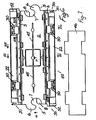
- FIG. 6 to 21 there is shown another cable duct 40 which is largely similar to the cable duct previously described with reference to Figs. 1 to 5 and like parts are assigned the same reference numerals.
- a number of knock-out panels 41 are provided in the side walls 3 and base 2 to allow cable entry and exit.
- a number of upstanding ribs 42 are provided beneath the base 2 extending between opposite sides of the duct 1 to provide strength and, as can be seen in Fig. 8, the underside of the duct 1 is of generally box section.
- the box section and ribbing allows the duct to bite into track-side ballast and soils. Further, the ribbing allows the mould for forming the duct 1 to readily and quickly fill during the moulding process.
- Central slots 45 (Fig. 6) are provided in the base 2 for reception of an upstanding divider panel 46 and to allow drainage.
- Expansion means 50 is provided at each end of the duct to accommodate longitudinal expansion and contraction of the duct comprising a curved flange 51 on one side and an associated curved housing 52 on the other side. As shown in Fig. 11 a pair of ducts 40 rotatably engage to interlock associated flanges 51 and housings 52 of adjacent ducts 40.
- the expansion means 50 allows up to 6 mm longitudinal expansion of the duct to be absorbed.
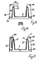
- the cover 20 has a generally flat top 60 with a peripheral rim 61 which projects slightly above the top 60 and extends downwardly of the top 60. Ribs 62 extend downwardly from an inner surface of the top 60 within the rim 61. These ribs 62 ensure high strength and loading capability and ease the flow of material within the mould during the moulding process for forming the cover 20.
- the top 60 is provided with a number of upstanding spaced-apart projections 64 which provide an anti-slip surface.
- a plurality of water drainage slots 65 are provided in the rim 61 to prevent water or frost build-up on the cover which would provide a slip hazard.
- Expansion means for the cover 20 comprises an outwardly projecting tongue 63 at one end of the cover 20 and an associated socket 69 at the opposite end of the cover 20. On interlocked ducts the tongues 63 and sockets 69 of adjacent covers 20 overlap to prevent ingress of dirt.
- a standard cover 20 or a locking cover 70 may be provided for the ducts 1,40.
- the locking cover 70 has a slot 71 extending through a neck portion 72 between the projections 67 for reception of a locking plate 74, outer ends of which engage complementary slots 75 at an upper end of the housing 30 on the duct 1,40.
- Locking bolts 77 extend through associated holes 78 in the neck portion 72 to engage the locking plates 74 to secure the cover 70 on the duct 1,40.
- a T-junction 80 of similar construction to the duct 1,40 is shown which allows various bending radii of telecommunications and fibre optic cables to be accommodated.
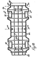
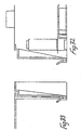
- the interlocking means comprises a male connector 91 at one end of the duct 90 and a complementary female receiver 92 at the opposite end of the duct 90.
- the male connector 91 has a bulbous head 93.
- a narrowed neck portion 94 connects the bulbous head 93 to the base 2.
- the female receiver 92 comprises a re-entrant slot having an inner portion 95 for reception of the bulbous head 93 and a narrowed mouth 96 defined by pillars 97 which engage behind the bulbous head 93 with the neck 94.
- a pair of ducts 90 can be interlocked by engaging the bulbous head 93 of one duct 90 within the enlarged inner portion 95 of the female receiver 92.
- the width of the bulbous head 93 is somewhat smaller than the depth of the inner portion 93 and the neck 94 is somewhat deeper than the pillars 97 to allow for expansion and contraction of the ducts.
- Complementary inter-engagable formations are provided on the male connector 91 and the female receiver 92 to prevent relative vertical displacement of a pair of interconnected ducts 90.
- the formations comprise a pair of outwardly extending lugs 98 on opposite sides of the bulbous head 93 at the bottom of the bulbous head 93. These lugs 98 are engagable with associated slots 99 provided at each side of the inner portion 95 of the female receiver 92.
- wings 100 are provided at an upper end of the neck 94 for engagement with associated stepped grooves 101 at an upper end of each pillar 97.
- a plurality of the ducts 1, 40, 90 can be laid end to end alongside a track, the ducts interlocking to form a continuous channel for cables.
- the ducts in 1, 40, 90 can be buried in track-side ballast, the interlocking devices 5 preventing unauthorised dismantling of the channel formed by the ducts 1,40, 90 by vandals.
- any suitable locking means may be provided for releasably locking the cover on the duct.
- the ducts may be also use for housing pipework or the like.
Landscapes
- Engineering & Computer Science (AREA)
- Architecture (AREA)
- Civil Engineering (AREA)
- Structural Engineering (AREA)
- Laying Of Electric Cables Or Lines Outside (AREA)
- Details Of Indoor Wiring (AREA)
- Body Structure For Vehicles (AREA)
- Seal Device For Vehicle (AREA)
- Extrusion Moulding Of Plastics Or The Like (AREA)
Claims (16)
- Kabelkanal (40) mit einer Basis (2) mit aufrechten Seitenwänden (3) an gegenüberliegenden Seiten der Basis (2), die mit der Basis (2) einen Kanal mit offenem Ende zur Aufnahme von Kabeln bilden, und ein Mittel (5) an jedem Ende des Kanals (40), um den Kanal (40) Ende an Ende in einen anderen Kanal (40) eingreifen zu lassen, um einen verlängerten Kanal für Kabel oder dergleichen zu bilden, dadurch gekennzeichnet, dass ein Verlängerungsmittel (50) bereitgestellt ist, um eine Verlängerung in Längsrichtung von benachbarten Kanälen (40) zu ermöglichen, wenn sie Ende an Ende ineinander eingreifen, wobei das Verlängerungsmittel einander ergänzende Strukturen (51, 52), die ineinander eingreifen können, an jedem Ende des Kanals (40) umfasst, wobei sich die zugehörigen Strukturen (51, 52) an einem Paar Kanäle (40) beim Eingreifen des Paars Kanäle (40) überlappen, um das Eindringen von Material in die Kanäle (40) zu verhindern.
- Kabelkanal (40) nach Anspruch 1, wobei ein Mittel (6, 8) bereitgestellt ist, um eine relative vertikale Bewegung zwischen einem Paar ineinander eingreifender Kanäle zu verhindern.
- Kabelkanal (40) nach einem der vorhergehenden Ansprüche, wobei das Verlängerungsmittel (50) einander ergänzende Strukturen (51, 52), die ineinander eingreifen können, an jedem Ende des Kanals (40) umfasst, wobei die Strukturen (51, 52) von mindestens einem Ende des Kanals (40) auswärts vorstehen, so dass sich die zugehörigen Strukturen an einem Paar Kanäle (40) beim Einklinken der Kanäle (40) überlappen, um das Eindringen von Material in die Kanäle (40) zu verhindern, wobei eine Abdeckung (20) für den Kanal (40) ebenfalls mit sich überlappenden Verlängerungsstrukturen an jedem Ende der Abdeckung (20) für einen überlappenden Eingriff in benachbarte Abdeckungen (20) versehen ist.
- Kabelkanal (40) nach einem der vorhergehenden Ansprüche, wobei das Verlängerungsmittel (50) an jedem Ende des Kanals einen gekrümmten Flansch (51) an einer Seitenwand (3) und ein zugehöriges gekrümmtes Gehäuse (52) an der anderen Seitenwand (3) umfasst, wobei der Flansch (51) eines Kanals (40) beim Verriegeln der Kanäle (40) drehbar in das Gehäuse (52) an einem benachbarten Kanal (40) eingreifen kann.
- Kabelkanal (40) nach einem der vorhergehenden Ansprüche, wobei ein Befestigungsmittel (30) an dem Kanal (40) bereitgestellt ist, um den Kanal (40) an einem oder mehreren Stützpfosten (32) zu befestigen.
- Kabelkanal (40) nach einem der vorhergehenden Ansprüche, wobei ein sich auswärts erstreckender Schuh (22) an einem unteren Ende jeder Seitenwand (3) bereitgestellt ist, um den Kanal (40) in einem Fundamentmaterial zu verkeilen, wobei eine obere Seite des Schuhs (22) aufwärts und auswärts schräg von der Seitenwand (3) absteht.
- Kabelkanal (40) nach einem der vorhergehenden Ansprüche, wobei das Kanalverriegelungsmittel eine zweiteilige Konstruktion aufweist, die einen Stecker (91) umfasst, der lösbar mit einer komplementären Buchse (92) in Eingriff gebracht werden kann, wobei eines der Teile (91, 92) an jedem Ende des Kanals (90) bereitgestellt ist.
- Kabelkanal (40) nach einem der vorhergehenden Ansprüche, wobei das Verriegelungsmittel (5) einen gekrümmten Zapfen (6) an jedem Ende des Kanals (40) umfasst und jeder Zapfen (6) für einen Hakeneingriff in einen komplementären Zapfen (6) an einem anderen Kanal (40) bestimmt ist.
- Kabelkanal (40) nach Anspruch 8, wobei das Mittel zum Verhindern einer relativen vertikalen Bewegung zwischen einem Paar in Eingriff stehender Kanäle eine Zunge (8) umfasst, die zu jedem Zapfen (6) gehört, wobei die Zunge (8) von dem Zapfen (6) beabstandet und im Verhältnis zu dem Zapfen (6) vertikal verschoben ist, so dass, wenn ein Paar Zapfen (6) ineinander eingreifen, eine Zunge (8), die zu einem der Zapfen (6) gehört, unterhalb des anderen Zapfens (8) eingreift.
- Kabelkanal (90) nach Anspruch 7, wobei der Stecker (91) einen knolligen Kopf (93) umfasst, der mittels eines verengten Halses (94) mit der Basis (2) verbunden ist, und die Buchse (92) einen Schlitz für ein wiederholtes Einführen (95) in der Basis (2) umfasst.
- Kabelkanal nach einem der vorhergehenden Ansprüche, wobei die Basis (2) einen Entwässerungskanal (45) in einer oberen Fläche der Basis (2) aufweist.
- Kabelkanal nach einem der vorhergehenden Ansprüche, wobei eine Schulter (17) an einem oberen Ende jeder Seitenwand (3) gebildet ist, um eine Abdeckung (20) aufzunehmen, die zwischen den Seitenwänden (3) eingreifen kann, um den Kanal zu schließen, wobei die Schulter (17) eine auswärts und abwärts abfallende obere Fläche aufweist, um das Ablaufen von Wasser zu ermöglichen.
- Kabelkanal nach Anspruch 12, wobei eine Gelenkbefestigung (36) an einem oberen Ende einer oder beider Seitenwände (3) gebildet ist, um die Abdeckung (20) gelenkig an den Seitenwänden (3) zu befestigen.
- Kabelkanal nach Anspruch 12 oder 13, wobei ein oder mehrere Wasserablaufschlitze (65) an einer Kante einer oberen Fläche der Abdeckung (20) bereitgestellt sind.
- Kabelkanal nach einem der Ansprüche 12 bis 14, wobei ein oder mehrere Gelenkstifte (37) an einer Kante der Abdeckung (20) bereitgestellt sind, um in die Gelenkbefestigung (36) am Kanal einzugreifen.
- Kabelkanal nach einem der Ansprüche 12 bis 15, wobei ein Verriegelungsmittel (74, 77) bereitgestellt ist, um die Abdeckung (20) lösbar am Kanal zu befestigen.
Applications Claiming Priority (2)
| Application Number | Priority Date | Filing Date | Title |
|---|---|---|---|
| IE950850 | 1995-11-03 | ||
| IE950850 | 1995-11-03 |
Publications (3)
| Publication Number | Publication Date |
|---|---|
| EP0772271A2 EP0772271A2 (de) | 1997-05-07 |
| EP0772271A3 EP0772271A3 (de) | 1998-05-06 |
| EP0772271B1 true EP0772271B1 (de) | 2005-10-26 |
Family
ID=11040952
Family Applications (1)
| Application Number | Title | Priority Date | Filing Date |
|---|---|---|---|
| EP96650049A Expired - Lifetime EP0772271B1 (de) | 1995-11-03 | 1996-11-04 | Kabelkanal |
Country Status (4)
| Country | Link |
|---|---|
| EP (1) | EP0772271B1 (de) |
| AT (1) | ATE308138T1 (de) |
| AU (1) | AU721837B2 (de) |
| DE (1) | DE69635335D1 (de) |
Families Citing this family (4)
| Publication number | Priority date | Publication date | Assignee | Title |
|---|---|---|---|---|
| EP1102376B1 (de) * | 1999-11-19 | 2003-07-23 | Tehalit GmbH & Co. KG | Kabelkanal |
| WO2002027882A1 (en) * | 2000-09-26 | 2002-04-04 | Andrews Kent And Stone Pty Ltd | Ducting associated with rail track and installing apparatus |
| GB0422958D0 (en) | 2004-10-15 | 2004-11-17 | Trojan Services Ltd | Improvements in and relating to trunking |
| GB2597102A (en) * | 2020-07-15 | 2022-01-19 | Trojan Services Ltd | A foundation unit |
Family Cites Families (5)
| Publication number | Priority date | Publication date | Assignee | Title |
|---|---|---|---|---|
| DE7015776U (de) * | 1970-04-27 | 1970-11-26 | Niedax Gmbh | Registerschienenelement. |
| DE2124163C2 (de) * | 1971-05-14 | 1981-10-15 | Tehalit Kunststoffwerk Gmbh, 6751 Heltersberg | Unterputzkabelführungskanal |
| BE795365A (nl) * | 1972-02-22 | 1973-05-29 | Gouda Holland N V | Gootvormig lichaam voor het kanaliseren van elektrische kabels |
| DE8018534U1 (de) * | 1980-07-10 | 1981-01-15 | Licentia Patent-Verwaltungs-Gmbh, 6000 Frankfurt | Kabeldurchführung |
| DE8605355U1 (de) * | 1986-02-27 | 1991-02-28 | Thyssen Polymer Gmbh, 8000 Muenchen, De |
-
1996
- 1996-11-04 AU AU70572/96A patent/AU721837B2/en not_active Expired
- 1996-11-04 DE DE69635335T patent/DE69635335D1/de not_active Expired - Fee Related
- 1996-11-04 EP EP96650049A patent/EP0772271B1/de not_active Expired - Lifetime
- 1996-11-04 AT AT96650049T patent/ATE308138T1/de not_active IP Right Cessation
Also Published As
| Publication number | Publication date |
|---|---|
| AU7057296A (en) | 1997-05-08 |
| EP0772271A3 (de) | 1998-05-06 |
| EP0772271A2 (de) | 1997-05-07 |
| ATE308138T1 (de) | 2005-11-15 |
| AU721837B2 (en) | 2000-07-13 |
| DE69635335D1 (de) | 2005-12-01 |
Similar Documents
| Publication | Publication Date | Title |
|---|---|---|
| US4826351A (en) | Grid plate of plastic material | |
| EP1437447B1 (de) | Verfahren und Vorrichtung zum Ausrichten von Kanalelementen mit verstellbarem Ausrichtschlüssel | |
| US4640643A (en) | Sidewall extension for drain channel system and method for extending the continuous slope of a drainage channel system | |
| US6484451B1 (en) | Stackable riser resistant to soil movement | |
| JP2003510480A (ja) | トレンチカバー要素 | |
| PL176322B1 (pl) | Element kanału kablowego | |
| US11600980B2 (en) | Cable trough with an integrated walkway function for use in railways | |
| US6712546B1 (en) | Polymeric forms for moldable building material structures | |
| EP0772271B1 (de) | Kabelkanal | |
| US6203245B1 (en) | Culvert end guard | |
| EP1807918B1 (de) | Verbesserungen eines kabelkanalsystems | |
| GB2238815A (en) | Trench cover | |
| WO1994001907A1 (en) | Cable channelling | |
| WO1998047212A1 (en) | Improvements in and relating to cable ducts and walkways | |
| US1350306A (en) | Manhole construction | |
| KR100929498B1 (ko) | 교량용 케이블 트로프 | |
| KR20080074523A (ko) | 케이블 매설용 트로프 및 이의 시공방법 | |
| US20050081437A1 (en) | Modular element for forming lawn or flowerbed borders or the like | |
| US20220344923A1 (en) | A combined cable trough and walkway | |
| JP2000017720A (ja) | 水路用ブロック | |
| US5179752A (en) | Cover for trenches | |
| GB2257490A (en) | Ducting | |
| JPH0343814Y2 (de) | ||
| CA2476893A1 (en) | Modular element for forming lawn or flowerbed borders or the like | |
| US20230344211A1 (en) | Cable housing container |
Legal Events
| Date | Code | Title | Description |
|---|---|---|---|
| PUAI | Public reference made under article 153(3) epc to a published international application that has entered the european phase |
Free format text: ORIGINAL CODE: 0009012 |
|
| AK | Designated contracting states |
Kind code of ref document: A2 Designated state(s): AT BE CH DE DK ES FI FR GB GR IE IT LI LU MC NL PT SE |
|
| PUAL | Search report despatched |
Free format text: ORIGINAL CODE: 0009013 |
|
| AK | Designated contracting states |
Kind code of ref document: A3 Designated state(s): AT BE CH DE DK ES FI FR GB GR IE IT LI LU MC NL PT SE |
|
| 17P | Request for examination filed |
Effective date: 19981105 |
|
| 17Q | First examination report despatched |
Effective date: 20040315 |
|
| GRAP | Despatch of communication of intention to grant a patent |
Free format text: ORIGINAL CODE: EPIDOSNIGR1 |
|
| GRAS | Grant fee paid |
Free format text: ORIGINAL CODE: EPIDOSNIGR3 |
|
| GRAA | (expected) grant |
Free format text: ORIGINAL CODE: 0009210 |
|
| AK | Designated contracting states |
Kind code of ref document: B1 Designated state(s): AT BE CH DE DK ES FI FR GB GR IE IT LI LU MC NL PT SE |
|
| PG25 | Lapsed in a contracting state [announced via postgrant information from national office to epo] |
Ref country code: NL Free format text: LAPSE BECAUSE OF FAILURE TO SUBMIT A TRANSLATION OF THE DESCRIPTION OR TO PAY THE FEE WITHIN THE PRESCRIBED TIME-LIMIT Effective date: 20051026 Ref country code: LI Free format text: LAPSE BECAUSE OF FAILURE TO SUBMIT A TRANSLATION OF THE DESCRIPTION OR TO PAY THE FEE WITHIN THE PRESCRIBED TIME-LIMIT Effective date: 20051026 Ref country code: IT Free format text: LAPSE BECAUSE OF FAILURE TO SUBMIT A TRANSLATION OF THE DESCRIPTION OR TO PAY THE FEE WITHIN THE PRESCRIBED TIME-LIMIT;WARNING: LAPSES OF ITALIAN PATENTS WITH EFFECTIVE DATE BEFORE 2007 MAY HAVE OCCURRED AT ANY TIME BEFORE 2007. THE CORRECT EFFECTIVE DATE MAY BE DIFFERENT FROM THE ONE RECORDED. Effective date: 20051026 Ref country code: FI Free format text: LAPSE BECAUSE OF FAILURE TO SUBMIT A TRANSLATION OF THE DESCRIPTION OR TO PAY THE FEE WITHIN THE PRESCRIBED TIME-LIMIT Effective date: 20051026 Ref country code: CH Free format text: LAPSE BECAUSE OF FAILURE TO SUBMIT A TRANSLATION OF THE DESCRIPTION OR TO PAY THE FEE WITHIN THE PRESCRIBED TIME-LIMIT Effective date: 20051026 Ref country code: BE Free format text: LAPSE BECAUSE OF FAILURE TO SUBMIT A TRANSLATION OF THE DESCRIPTION OR TO PAY THE FEE WITHIN THE PRESCRIBED TIME-LIMIT Effective date: 20051026 Ref country code: AT Free format text: LAPSE BECAUSE OF FAILURE TO SUBMIT A TRANSLATION OF THE DESCRIPTION OR TO PAY THE FEE WITHIN THE PRESCRIBED TIME-LIMIT Effective date: 20051026 |
|
| REG | Reference to a national code |
Ref country code: GB Ref legal event code: FG4D |
|
| REG | Reference to a national code |
Ref country code: CH Ref legal event code: EP |
|
| PG25 | Lapsed in a contracting state [announced via postgrant information from national office to epo] |
Ref country code: MC Free format text: LAPSE BECAUSE OF NON-PAYMENT OF DUE FEES Effective date: 20051130 |
|
| REG | Reference to a national code |
Ref country code: IE Ref legal event code: FG4D |
|
| REF | Corresponds to: |
Ref document number: 69635335 Country of ref document: DE Date of ref document: 20051201 Kind code of ref document: P |
|
| PG25 | Lapsed in a contracting state [announced via postgrant information from national office to epo] |
Ref country code: LU Free format text: LAPSE BECAUSE OF NON-PAYMENT OF DUE FEES Effective date: 20051226 |
|
| PG25 | Lapsed in a contracting state [announced via postgrant information from national office to epo] |
Ref country code: SE Free format text: LAPSE BECAUSE OF FAILURE TO SUBMIT A TRANSLATION OF THE DESCRIPTION OR TO PAY THE FEE WITHIN THE PRESCRIBED TIME-LIMIT Effective date: 20060126 Ref country code: GR Free format text: LAPSE BECAUSE OF FAILURE TO SUBMIT A TRANSLATION OF THE DESCRIPTION OR TO PAY THE FEE WITHIN THE PRESCRIBED TIME-LIMIT Effective date: 20060126 Ref country code: DK Free format text: LAPSE BECAUSE OF FAILURE TO SUBMIT A TRANSLATION OF THE DESCRIPTION OR TO PAY THE FEE WITHIN THE PRESCRIBED TIME-LIMIT Effective date: 20060126 |
|
| PG25 | Lapsed in a contracting state [announced via postgrant information from national office to epo] |
Ref country code: ES Free format text: LAPSE BECAUSE OF FAILURE TO SUBMIT A TRANSLATION OF THE DESCRIPTION OR TO PAY THE FEE WITHIN THE PRESCRIBED TIME-LIMIT Effective date: 20060206 |
|
| PG25 | Lapsed in a contracting state [announced via postgrant information from national office to epo] |
Ref country code: PT Free format text: LAPSE BECAUSE OF FAILURE TO SUBMIT A TRANSLATION OF THE DESCRIPTION OR TO PAY THE FEE WITHIN THE PRESCRIBED TIME-LIMIT Effective date: 20060327 |
|
| NLV1 | Nl: lapsed or annulled due to failure to fulfill the requirements of art. 29p and 29m of the patents act | ||
| REG | Reference to a national code |
Ref country code: CH Ref legal event code: PL |
|
| PG25 | Lapsed in a contracting state [announced via postgrant information from national office to epo] |
Ref country code: DE Free format text: LAPSE BECAUSE OF NON-PAYMENT OF DUE FEES Effective date: 20060601 |
|
| PLBE | No opposition filed within time limit |
Free format text: ORIGINAL CODE: 0009261 |
|
| STAA | Information on the status of an ep patent application or granted ep patent |
Free format text: STATUS: NO OPPOSITION FILED WITHIN TIME LIMIT |
|
| 26N | No opposition filed |
Effective date: 20060727 |
|
| EN | Fr: translation not filed | ||
| PG25 | Lapsed in a contracting state [announced via postgrant information from national office to epo] |
Ref country code: FR Free format text: LAPSE BECAUSE OF FAILURE TO SUBMIT A TRANSLATION OF THE DESCRIPTION OR TO PAY THE FEE WITHIN THE PRESCRIBED TIME-LIMIT Effective date: 20061215 |
|
| PG25 | Lapsed in a contracting state [announced via postgrant information from national office to epo] |
Ref country code: FR Free format text: LAPSE BECAUSE OF FAILURE TO SUBMIT A TRANSLATION OF THE DESCRIPTION OR TO PAY THE FEE WITHIN THE PRESCRIBED TIME-LIMIT Effective date: 20051130 |
|
| PG25 | Lapsed in a contracting state [announced via postgrant information from national office to epo] |
Ref country code: FR Free format text: LAPSE BECAUSE OF FAILURE TO SUBMIT A TRANSLATION OF THE DESCRIPTION OR TO PAY THE FEE WITHIN THE PRESCRIBED TIME-LIMIT Effective date: 20051026 |
|
| REG | Reference to a national code |
Ref country code: GB Ref legal event code: 732E Free format text: REGISTERED BETWEEN 20101007 AND 20101013 |
|
| PGFP | Annual fee paid to national office [announced via postgrant information from national office to epo] |
Ref country code: IE Payment date: 20150908 Year of fee payment: 20 Ref country code: GB Payment date: 20150922 Year of fee payment: 20 |
|
| REG | Reference to a national code |
Ref country code: GB Ref legal event code: PE20 Expiry date: 20161103 |
|
| REG | Reference to a national code |
Ref country code: IE Ref legal event code: MK9A |
|
| PG25 | Lapsed in a contracting state [announced via postgrant information from national office to epo] |
Ref country code: IE Free format text: LAPSE BECAUSE OF EXPIRATION OF PROTECTION Effective date: 20161104 Ref country code: GB Free format text: LAPSE BECAUSE OF EXPIRATION OF PROTECTION Effective date: 20161103 |