EP0772058A2 - Système d'identification et/ou de détection - Google Patents
Système d'identification et/ou de détection Download PDFInfo
- Publication number
- EP0772058A2 EP0772058A2 EP96114846A EP96114846A EP0772058A2 EP 0772058 A2 EP0772058 A2 EP 0772058A2 EP 96114846 A EP96114846 A EP 96114846A EP 96114846 A EP96114846 A EP 96114846A EP 0772058 A2 EP0772058 A2 EP 0772058A2
- Authority
- EP
- European Patent Office
- Prior art keywords
- phase
- identification
- sensor system
- locked loop
- detector
- Prior art date
- Legal status (The legal status is an assumption and is not a legal conclusion. Google has not performed a legal analysis and makes no representation as to the accuracy of the status listed.)
- Granted
Links
Images




Classifications
-
- G—PHYSICS
- G01—MEASURING; TESTING
- G01S—RADIO DIRECTION-FINDING; RADIO NAVIGATION; DETERMINING DISTANCE OR VELOCITY BY USE OF RADIO WAVES; LOCATING OR PRESENCE-DETECTING BY USE OF THE REFLECTION OR RERADIATION OF RADIO WAVES; ANALOGOUS ARRANGEMENTS USING OTHER WAVES
- G01S13/00—Systems using the reflection or reradiation of radio waves, e.g. radar systems; Analogous systems using reflection or reradiation of waves whose nature or wavelength is irrelevant or unspecified
- G01S13/74—Systems using reradiation of radio waves, e.g. secondary radar systems; Analogous systems
- G01S13/75—Systems using reradiation of radio waves, e.g. secondary radar systems; Analogous systems using transponders powered from received waves, e.g. using passive transponders, or using passive reflectors
- G01S13/751—Systems using reradiation of radio waves, e.g. secondary radar systems; Analogous systems using transponders powered from received waves, e.g. using passive transponders, or using passive reflectors wherein the responder or reflector radiates a coded signal
-
- G—PHYSICS
- G06—COMPUTING OR CALCULATING; COUNTING
- G06K—GRAPHICAL DATA READING; PRESENTATION OF DATA; RECORD CARRIERS; HANDLING RECORD CARRIERS
- G06K19/00—Record carriers for use with machines and with at least a part designed to carry digital markings
- G06K19/06—Record carriers for use with machines and with at least a part designed to carry digital markings characterised by the kind of the digital marking, e.g. shape, nature, code
- G06K19/067—Record carriers with conductive marks, printed circuits or semiconductor circuit elements, e.g. credit or identity cards also with resonating or responding marks without active components
- G06K19/07—Record carriers with conductive marks, printed circuits or semiconductor circuit elements, e.g. credit or identity cards also with resonating or responding marks without active components with integrated circuit chips
- G06K19/0723—Record carriers with conductive marks, printed circuits or semiconductor circuit elements, e.g. credit or identity cards also with resonating or responding marks without active components with integrated circuit chips the record carrier comprising an arrangement for non-contact communication, e.g. wireless communication circuits on transponder cards, non-contact smart cards or RFIDs
Definitions
- the present invention relates to an identification and / or sensor system according to the preamble of patent claim 1.
- Identification and / or sensor systems of the generic type are known for example from DE-OS 42 17 049. These are systems with passive surface wave sensors for measuring value determination, in which a transmitting and receiving device transmits energy to a sensor element contained in the surface wave sensor as a query pulse. Such systems are suitable for contactless measurement value acquisition, the sensor element working with surface acoustic waves and a reference element also working with surface acoustic waves being provided for phase discrimination and / or transit time measurement.
- the response signals decay with a time function which is given by the energy decay time of the resonators.
- the present invention is based on the object of specifying a possibility for converting the decay of resonators into signals of constant frequency.
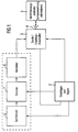
- an identification and / or sensor system generally contains a transmitter 1 and a receiver and controller 2, which are coupled to an antenna 4 via a transmission / reception switch. Via the transmit / receive changeover switch 3 and the antenna 4, a query signal is sent from the transmitter 1 to an identification and / or sensor arrangement with antenna 5, which as a function of the query signal generates a response signal via the antenna 4 and the transmit / receive changeover switch 3 to the receiver and Controller 2 sends back.
- the transmitter 1 contains a frequency synthesizer 6 controlled by the receiver and controller 2, which is coupled to the transmission / reception switch 3 via a switch 7 and an amplifier 8.
- the switch 7 is controlled by the receiver and controller 2 and switches the frequency synthesizer 6 for that Transmission of the interrogation signal via the amplifier 8 to the transmission / reception switch 3, which is switched over by the receiver and controller 2 to transmission or reception.
- the response signals decay according to a time function which is given by the energy swinging out in the resonators.
- the receiver contains a phase locked loop sensed by the response signal and a threshold value detector which controls a sample and hold circuit in the phase locked loop and is triggered by the response signal .
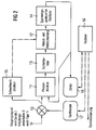
- a phase locked loop contains a phase detector 11, a sample and hold circuit 12, a loop filter 13 and a voltage-controlled oscillator 14 which is fed back to the phase detector 11.
- the phase detector 11 can be a ring mixer, the phase detector constant of which is determined by the product of the amplitudes of the input signal and the signal of the voltage-controlled oscillator 14. This enables an intervention in the properties of the receiver. By keeping the product of the two amplitudes constant, the exponential decay of the input signal can be corrected.
- An input signal from the transmission / reception switch 3 according to FIG. 1 is input into a mixer 10, in which it is mixed with a signal from a frequency synthesizer 17 to form a signal of a suitable frequency for the phase-locked loop 11 to 14.
- An output signal of the mixer 10 with a sufficient signal-to-noise ratio is determined by a threshold value detector 15, which controls the sample and hold circuit 12 in the phase-locked loop 11 to 14. If there is a mixer output signal with a sufficient signal-to-noise ratio, then so the phase-locked loop is closed and the voltage-controlled oscillator 14 is synchronized with the input signal within a few periods.
- the dynamic behavior and permissible frequency deviations are determined by the loop filter 13 according to a further feature of the invention.
- the phase-locked loop 11 to 14 is opened via the sample and hold circuit 12, so that the voltage-controlled oscillator 14 oscillates freely as a function of the control voltage supplied by the sample and hold circuit 12.
- the output signal of the voltage-controlled oscillator 14 is periodically readjusted to the frequency and the phase of the resonator response signal with a constant amplitude.
- the frequency of the output signal of the voltage-controlled oscillator 14 can be determined very precisely by counting over long periods using a counter 16.
- a computer control is provided by means of a computer 18, which receives the frequency information from the counter 16 and controls both the frequency synthesizer 17 and the interrogation signal and the transmitter 1 according to FIG. It is an adaptive readjustment of the interrogation signal and the frequency of the synthesizer 17 and possibly the duration and the amplitude of the interrogation signal and thus its energy and bandwidth.
- a broad frequency range can be searched in a first scan cycle with short scan pulses. After measuring a resonator response signal, the resonator is subjected to wider, narrow-band interrogation signals with the greatest possible pump energy, so that it is very precise in its Decay frequency can be determined. For constant query energy, the transmitted transmission power can be reduced by reducing the signal bandwidth.
- a further embodiment made possible by the computer control is a narrow-band resonator query with a frequency difference due to a change in the measured value with little influence by other resonators.
- a ring mixer can be provided as the phase detector 11, by means of which the phase detector constant can be influenced by the product of the amplitudes of the input signal and the local oscillator and control by the amplitude of the oscillator 14 can take place.
- an amplifier 19 is connected upstream of the phase detector 11 to keep the amplitude constant with minimal distortion of the signal phase.
- This amplifier 19 can be designed as a limiter amplifier or a logarithmic amplifier. Because of this amplifier 19, the signal amplitude at the input of the phase-locked loop 11 to 14 has an approximately constant amplitude in the entire dynamic range of typically 50 to 100 dB, thereby preventing the phase-locked loop from being influenced.
- the mode of operation of the embodiment according to FIG. 3 otherwise corresponds to the mode of operation of the embodiment according to FIG. 2 and therefore need not be explained again here.
- FIG. 4 A further embodiment of a receiver of an identification and / or sensor system according to the invention is shown in FIG. 4, in which the same elements as in FIGS. 2 and 3 are provided with the same reference numerals.
- a threshold value detector 20 which is driven by the mixer output signal, is designed as an adaptive detector, which supplies two threshold value signals with different high levels, which are denoted in FIG. 4 by "low level” and "high level”.
- a changeover switch 21, which is controlled by the threshold value detector 20, is provided, which is coupled once via the sample and hold circuit 12 and once directly to the phase detector 11. There are only steady signals at the input of the loop filter 13 and thus also at the input of the voltage-controlled oscillator 14.
- the threshold detector 20 supplies the output signal for a high input signal level, as a result of which the sample and hold circuit 12 is switched to sampling mode and the changeover switch 21 directly to the Output of the phase detector 11 is switched.
- the phase locked loop is now engaged. If the signal level at the output of the mixer and thus at the input of the threshold detector 20 decreases, then this delivers the output signal for a low input signal level, whereby the sample and hold circuit is switched to hold mode and the changeover switch 21 switches the hold signal from the sample and hold circuit 12 to the loop filter 13 couples.
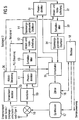
- FIG. 5 A further embodiment of a receiver for an identification and / or sensor system according to the invention is shown in FIG. 5, in which the same elements as in FIGS. 2 to 4 are provided with the same reference numerals.
- two phase locked loops 11, 12, 13, 14 and 31, 32, 33, 34 are provided.
- the outputs of the two phase locked loops 11 to 14 and 31 to 34 are coupled to a changeover switch 35.
- this threshold value detector 20 also supplies two threshold value signals for different levels of the input signal the output of this threshold value detector 20 is coupled to a sampling controller 36 which, as a function of the threshold value signals from the threshold value detector 20, supplies a key signal 1 for the phase locked loop 11 to 14 and a key signal 2 for the phase locked loop 31 to 34. Furthermore, this sampling control delivers a PLL control signal for the changeover switch 35, whereby either the phase locked loop 11 to 14 or the phase locked loop 31 to 35 is coupled to the counter 16.
- phase-locked loop 11 to 14 is synchronized with this signal. If this phase-locked loop 11 to 14 switches to hold mode, the phase-locked loop 31 to 35 is synchronized to the frequency and phase of the stable oscillating voltage-controlled oscillator 14 of the phase-locked loop 11 to 14.
- the counter 16 receives alternately at its input a signal of the phase-locked loop, which is frequency-stable in the holding mode.
- an analog-digital converter (ADC) 40 coupled to the output of the loop filter 13 is coupled, which converts the control voltage for the voltage-controlled oscillator 14 into a digital value.
- ADC analog-digital converter
- the measurement takes place in the locked state of the phase-locked loop 11 to 14, so that the long-term stability of the oscillator merely does not affect the transient response during the post-synchronization however, the measurement accuracy is affected.
- This is determined exclusively by the precision of the analog-to-digital converter 40 and the phase noise of the voltage-controlled oscillator 14. According to a special feature of the invention, an oscillator with low phase noise is therefore provided as the voltage-controlled oscillator 14.
- FIG. 7 shows an embodiment of an identification and / or sensor system according to the invention, in which the transmitter and receiver are not separate components.
- the voltage-controlled oscillator 14 is coupled via the amplifier 8 to the transmission / reception switch 3 controlled by the computer 18 and to a shunt branch 50, 51, 52, which is controlled by the computer 18 and which is connected in parallel, which has a shunt switch 50, a phase correction circuit 51 connected downstream thereof and one of these downstream damping circuit 52 contains.
- the two branches are coupled via the amplifier 19 to the phase detector 11, which in turn is coupled to the loop filter 13.
- phase detector 11 is coupled to a further loop filter 53, which is coupled to the voltage-controlled oscillator 14 via a snap-in detector 54, a generator 55 and a summation circuit 56, the summation stage 56 also being coupled to the loop filter 13.
- the transmit / receive changeover switch 3 and the shunt switch 50 are switched alternately.
- the query signal for the resonator identification and / or sensor arrangement 5 is generated via the transmit / receive changeover switch 3 and the antenna 4. After switching over the branches lying in parallel, the response signal is received by the arrangement 5 via the transmission / reception switch 3 switched to reception.
- the phase locked loop can be re-synchronized in the continuously locked state, even if in a signal of the appropriate frequency is available for the transmission intervals.
- the oscillation frequency of the voltage-controlled oscillator 14 is equal to the resonator natural frequency, so that the transmission signal can be used as a reference signal for stationary processes.
- This signal is coupled into the phase-locked loop via the shunt switch 50, the phase correction circuit 51 and the damping circuit 52.
- the phase correction circuit 51 causes a frequency-dependent phase delay in the feedback of the polling transmission signal and therefore prevents the voltage-controlled oscillator 14 from drifting away in transmission mode.
- a keyed phase-locked loop can also be used according to a further feature, as is present in the embodiments according to FIGS. 2 to 6.
- the phase locked loop in the above-described embodiments are designed as a digital phase locked loop (not specifically shown).
- a numerically controlled oscillator is used instead of a voltage controlled oscillator.
- the phase detector, the loop filter and all control functions are integrated in the control computer 18.
Landscapes
- Engineering & Computer Science (AREA)
- Remote Sensing (AREA)
- Radar, Positioning & Navigation (AREA)
- Computer Networks & Wireless Communication (AREA)
- Physics & Mathematics (AREA)
- General Physics & Mathematics (AREA)
- Theoretical Computer Science (AREA)
- Microelectronics & Electronic Packaging (AREA)
- Computer Hardware Design (AREA)
- Stabilization Of Oscillater, Synchronisation, Frequency Synthesizers (AREA)
- Transmission And Conversion Of Sensor Element Output (AREA)
- Arrangements For Transmission Of Measured Signals (AREA)
- Radar Systems Or Details Thereof (AREA)
- Investigating Or Analyzing Materials By The Use Of Electric Means (AREA)
Applications Claiming Priority (2)
| Application Number | Priority Date | Filing Date | Title |
|---|---|---|---|
| DE19539506 | 1995-10-24 | ||
| DE19539506 | 1995-10-24 |
Publications (3)
| Publication Number | Publication Date |
|---|---|
| EP0772058A2 true EP0772058A2 (fr) | 1997-05-07 |
| EP0772058A3 EP0772058A3 (fr) | 1998-12-09 |
| EP0772058B1 EP0772058B1 (fr) | 2003-01-08 |
Family
ID=7775600
Family Applications (1)
| Application Number | Title | Priority Date | Filing Date |
|---|---|---|---|
| EP96114846A Expired - Lifetime EP0772058B1 (fr) | 1995-10-24 | 1996-09-16 | Système d'identification et/ou de détection |
Country Status (4)
| Country | Link |
|---|---|
| US (1) | US5872520A (fr) |
| EP (1) | EP0772058B1 (fr) |
| JP (1) | JPH09133548A (fr) |
| DE (1) | DE59610041D1 (fr) |
Cited By (1)
| Publication number | Priority date | Publication date | Assignee | Title |
|---|---|---|---|---|
| WO2003050750A1 (fr) * | 2001-12-13 | 2003-06-19 | Canal + Technologies | Composant electronique numerique protege contre des analyses de type electrique |
Families Citing this family (31)
| Publication number | Priority date | Publication date | Assignee | Title |
|---|---|---|---|---|
| DE19741033A1 (de) * | 1997-09-18 | 1999-03-25 | Bosch Gmbh Robert | Übermitteln von Verkehrsinformationen für den Fahrer eines Fahrzeuges |
| DE10017572B4 (de) * | 2000-04-10 | 2008-04-17 | INSTITUT FüR MIKROTECHNIK MAINZ GMBH | Wälzlager mit fernabfragbaren Erfassungseinheiten |
| GB2363267B (en) * | 2000-06-07 | 2002-08-07 | Motorola Israel Ltd | Circuit and method for signal phase control in a radio transceiver |
| US6760454B1 (en) * | 2000-08-04 | 2004-07-06 | Trw Inc. | Passive voice-activated microphone and transceiver system |
| US6791489B1 (en) | 2001-03-12 | 2004-09-14 | Northrop Grumman Corporation | Radio tag for LFM radar |
| US6704383B2 (en) * | 2001-03-20 | 2004-03-09 | Gct Semiconductor, Inc. | Sample and hold type fractional-N frequency synthesizer |
| US6553089B2 (en) * | 2001-03-20 | 2003-04-22 | Gct Semiconductor, Inc. | Fractional-N frequency synthesizer with fractional compensation method |
| US7190907B2 (en) * | 2004-01-27 | 2007-03-13 | Northrop Grumman Corporation | Dynamic optical tag |
| US7146136B2 (en) * | 2004-02-04 | 2006-12-05 | Northrop Grumman Corporation | E-band radio transceiver architecture and chip set |
| US7436921B1 (en) * | 2004-11-05 | 2008-10-14 | Rockwell Collins, Inc. | Frequency sampling phase detector |
| EP1893080A2 (fr) | 2005-06-21 | 2008-03-05 | CardioMems, Inc. | Procede de fabrication de capteur sans fil implantable pour la mesure de pression in vivo |
| US8570186B2 (en) * | 2011-04-25 | 2013-10-29 | Endotronix, Inc. | Wireless sensor reader |
| US10003862B2 (en) | 2007-03-15 | 2018-06-19 | Endotronix, Inc. | Wireless sensor reader |
| US8154389B2 (en) * | 2007-03-15 | 2012-04-10 | Endotronix, Inc. | Wireless sensor reader |
| DE102010008391A1 (de) * | 2010-02-06 | 2011-08-11 | Silvia 73463 Möller | Eingebettetes Sensorsystem |
| EP3632303B1 (fr) | 2012-09-14 | 2022-02-02 | Endotronix, Inc. | Capteur de pression, ancrage, système de livraison et procédé |
| DE202016008639U1 (de) | 2015-02-12 | 2019-01-16 | Foundry Innovation & Research 1, Ltd. | Implantierbare Vorrichtungen zur Überwachung der Herzinsuffizienz |
| US12465324B2 (en) | 2015-02-12 | 2025-11-11 | Foundry Innovation & Research 1, Ltd. | Patient fluid management systems and methods employing integrated fluid status sensing |
| WO2018031714A1 (fr) | 2016-08-11 | 2018-02-15 | Foundry Innovation & Research 1, Ltd. | Systèmes et procédés de gestion des fluides chez un patient |
| EP3331426B1 (fr) | 2015-08-03 | 2024-07-24 | Foundry Innovation&Research 1, Ltd. | Catheter de mesure de dimension de veine cave |
| US9996712B2 (en) | 2015-09-02 | 2018-06-12 | Endotronix, Inc. | Self test device and method for wireless sensor reader |
| US11701018B2 (en) | 2016-08-11 | 2023-07-18 | Foundry Innovation & Research 1, Ltd. | Wireless resonant circuit and variable inductance vascular monitoring implants and anchoring structures therefore |
| US11206992B2 (en) | 2016-08-11 | 2021-12-28 | Foundry Innovation & Research 1, Ltd. | Wireless resonant circuit and variable inductance vascular monitoring implants and anchoring structures therefore |
| EP3463082B1 (fr) | 2016-11-29 | 2020-07-29 | Foundry Innovation & Research 1, Ltd. | Implants vasculaires à inductance variable et circuit résonant sans fil permettant de surveiller le système vasculaire |
| US11615257B2 (en) | 2017-02-24 | 2023-03-28 | Endotronix, Inc. | Method for communicating with implant devices |
| US10430624B2 (en) | 2017-02-24 | 2019-10-01 | Endotronix, Inc. | Wireless sensor reader assembly |
| EP3612084A1 (fr) | 2017-04-20 | 2020-02-26 | Endotronix, Inc. | Système d'ancrage pour un dispositif délivré par un cathéter |
| WO2018220143A1 (fr) | 2017-05-31 | 2018-12-06 | Foundry Innovation And Research 1, Ltd | Capteur vasculaire ultrasonore implantable |
| WO2018220146A1 (fr) | 2017-05-31 | 2018-12-06 | Foundry Innovation & Research 1, Ltd. | Capteurs implantables pour surveillance vasculaire |
| US11622684B2 (en) | 2017-07-19 | 2023-04-11 | Endotronix, Inc. | Physiological monitoring system |
| US12465233B2 (en) | 2022-07-29 | 2025-11-11 | Foundry Innovation & Research 1, Ltd. | Multistranded conductors adapted to dynamic in vivo environments |
Family Cites Families (7)
| Publication number | Priority date | Publication date | Assignee | Title |
|---|---|---|---|---|
| US3815029A (en) * | 1973-01-29 | 1974-06-04 | Us Air Force | Burst phase shift keyed receiver |
| US4099125A (en) * | 1976-06-23 | 1978-07-04 | Motorola, Inc. | Frequency error correction circuit |
| US4673932A (en) * | 1983-12-29 | 1987-06-16 | Revlon, Inc. | Rapid inventory data acquistion system |
| FR2564663B1 (fr) * | 1984-05-15 | 1986-09-19 | Radiotechnique | Demodulateur de frequence a largeur de bande ajustable |
| DE4217049A1 (de) * | 1992-05-22 | 1993-11-25 | Siemens Ag | Passiver Oberflächenwellen-Sensor, der drahtlos abfragbar ist |
| DE19510452C2 (de) * | 1994-04-07 | 1997-10-23 | Landis & Gyr Tech Innovat | Sende- und Empfangseinrichtung zur drahtlosen Abfrage eines physikalischen Parameters |
| DE59509359D1 (de) * | 1994-04-15 | 2001-08-02 | Siemens Ag | Sensorsystem |
-
1996
- 1996-09-16 DE DE59610041T patent/DE59610041D1/de not_active Expired - Lifetime
- 1996-09-16 EP EP96114846A patent/EP0772058B1/fr not_active Expired - Lifetime
- 1996-10-16 JP JP8294570A patent/JPH09133548A/ja active Pending
- 1996-10-24 US US08/736,371 patent/US5872520A/en not_active Expired - Lifetime
Cited By (2)
| Publication number | Priority date | Publication date | Assignee | Title |
|---|---|---|---|---|
| WO2003050750A1 (fr) * | 2001-12-13 | 2003-06-19 | Canal + Technologies | Composant electronique numerique protege contre des analyses de type electrique |
| FR2833724A1 (fr) * | 2001-12-13 | 2003-06-20 | Canal Plus Technologies | Composant electronique numerique protege contre des analyses de type electrique et/ou electromagnetique, notamment dans le domaine de la carte a puce |
Also Published As
| Publication number | Publication date |
|---|---|
| JPH09133548A (ja) | 1997-05-20 |
| DE59610041D1 (de) | 2003-02-13 |
| EP0772058B1 (fr) | 2003-01-08 |
| US5872520A (en) | 1999-02-16 |
| EP0772058A3 (fr) | 1998-12-09 |
Similar Documents
| Publication | Publication Date | Title |
|---|---|---|
| EP0772058B1 (fr) | Système d'identification et/ou de détection | |
| DE4498749C2 (de) | Phasensynchronisationsschaltung und entsprechendes Verfahren für einen phasenverriegelten Kreis | |
| DE68920761T2 (de) | Sender-Empfänger. | |
| DE69332685T2 (de) | Direktumsetzempfänger | |
| DE102016112168B4 (de) | Phasenregelschleife mit mehrband-oszillator und verfahren zum kalibrieren derselben | |
| DE69533924T2 (de) | Hf-transponder mit niedrigem stromverbrauch | |
| DE2225180B2 (de) | Drei-frequenz-dauerstrich-dopplerradargeraet mit paarweisem dopplersignalphasenvergleich unter entfernungsbereichbegrenzung | |
| DE2807578A1 (de) | Verfahren zur entfernungsmessung zwischen einer hauptstation und einer nebenstation | |
| DE69618524T2 (de) | Empfänger und Abstimmschaltung mit einem Frequenzsynthetisierer dafür | |
| DE19502111A1 (de) | Sendeempfänger für Zeitmultiplex-Mehrfachzugriff/Zeitmultiplex-Duplexbetrieb | |
| EP1141744A1 (fr) | Procede de detection et de correction de non-linearites d'oscillateurs commandes en tension haute frequence | |
| DE102017113730A1 (de) | Radar-frontend mit hf-oszillator-überwachung | |
| DE69226451T2 (de) | Signalübertragungssystem für Triggersonde | |
| EP1297357B1 (fr) | Dispositif pour la production d'un signal d'oscillateur | |
| DE2848148A1 (de) | Radargeraet mit kontinuierlicher schwingung | |
| EP1332549B1 (fr) | Systeme de dispositif melangeur photoelectrique (pmd) | |
| DE69022142T2 (de) | Pulsradargerät und für den Einbau in dieses Gerät geeignete Pulsdiskriminierungsschaltung. | |
| DE19635891C2 (de) | Empfänger | |
| DE102009027495A1 (de) | Heterodyn-Sende-/Empfangssysteme und Verfahren | |
| DE2531102C3 (de) | Radargerät zum Senden und Empfangen von Impulszügen mit von Impuls zu Impuls unterschiedlicher Frequenz | |
| DE2558258A1 (de) | Analogspeicherschaltung und mit dieser ausgestattete schaltungsanordnung | |
| DE19918057A1 (de) | Vorrichtung und Verfahren zur Einstellung der Abstimmspannung von Abstimmschwingkreisen | |
| HK54986A (en) | Hangup corrector useful in locked loop tuning system | |
| EP0170793B1 (fr) | Emetteur haute fréquence modulé par des signaux de données binaires | |
| DE69323362T2 (de) | Detektionsanordnung und Empfänger zum Empfang von HF-Signalen mit einer derartigen Detektionsanordnung |
Legal Events
| Date | Code | Title | Description |
|---|---|---|---|
| PUAI | Public reference made under article 153(3) epc to a published international application that has entered the european phase |
Free format text: ORIGINAL CODE: 0009012 |
|
| AK | Designated contracting states |
Kind code of ref document: A2 Designated state(s): DE FR GB |
|
| PUAL | Search report despatched |
Free format text: ORIGINAL CODE: 0009013 |
|
| AK | Designated contracting states |
Kind code of ref document: A3 Designated state(s): DE FR GB |
|
| 17P | Request for examination filed |
Effective date: 19990105 |
|
| RAP1 | Party data changed (applicant data changed or rights of an application transferred) |
Owner name: EPCOS AG |
|
| GRAG | Despatch of communication of intention to grant |
Free format text: ORIGINAL CODE: EPIDOS AGRA |
|
| 17Q | First examination report despatched |
Effective date: 20020325 |
|
| GRAG | Despatch of communication of intention to grant |
Free format text: ORIGINAL CODE: EPIDOS AGRA |
|
| GRAH | Despatch of communication of intention to grant a patent |
Free format text: ORIGINAL CODE: EPIDOS IGRA |
|
| GRAH | Despatch of communication of intention to grant a patent |
Free format text: ORIGINAL CODE: EPIDOS IGRA |
|
| GRAA | (expected) grant |
Free format text: ORIGINAL CODE: 0009210 |
|
| AK | Designated contracting states |
Kind code of ref document: B1 Designated state(s): DE FR GB |
|
| REG | Reference to a national code |
Ref country code: GB Ref legal event code: FG4D Free format text: NOT ENGLISH |
|
| GBT | Gb: translation of ep patent filed (gb section 77(6)(a)/1977) |
Effective date: 20030108 |
|
| REF | Corresponds to: |
Ref document number: 59610041 Country of ref document: DE Date of ref document: 20030213 Kind code of ref document: P |
|
| RAP2 | Party data changed (patent owner data changed or rights of a patent transferred) |
Owner name: EPCOS AG |
|
| ET | Fr: translation filed | ||
| PLBE | No opposition filed within time limit |
Free format text: ORIGINAL CODE: 0009261 |
|
| STAA | Information on the status of an ep patent application or granted ep patent |
Free format text: STATUS: NO OPPOSITION FILED WITHIN TIME LIMIT |
|
| 26N | No opposition filed |
Effective date: 20031009 |
|
| REG | Reference to a national code |
Ref country code: FR Ref legal event code: PLFP Year of fee payment: 20 |
|
| PGFP | Annual fee paid to national office [announced via postgrant information from national office to epo] |
Ref country code: GB Payment date: 20150922 Year of fee payment: 20 |
|
| PGFP | Annual fee paid to national office [announced via postgrant information from national office to epo] |
Ref country code: FR Payment date: 20150923 Year of fee payment: 20 |
|
| PGFP | Annual fee paid to national office [announced via postgrant information from national office to epo] |
Ref country code: DE Payment date: 20150924 Year of fee payment: 20 |
|
| REG | Reference to a national code |
Ref country code: DE Ref legal event code: R071 Ref document number: 59610041 Country of ref document: DE |
|
| REG | Reference to a national code |
Ref country code: GB Ref legal event code: PE20 Expiry date: 20160915 |
|
| PG25 | Lapsed in a contracting state [announced via postgrant information from national office to epo] |
Ref country code: GB Free format text: LAPSE BECAUSE OF EXPIRATION OF PROTECTION Effective date: 20160915 |