EP0772043B1 - Joint en fluoroélastomère pour capteurs d'analytes dans le sang - Google Patents
Joint en fluoroélastomère pour capteurs d'analytes dans le sang Download PDFInfo
- Publication number
- EP0772043B1 EP0772043B1 EP96307806A EP96307806A EP0772043B1 EP 0772043 B1 EP0772043 B1 EP 0772043B1 EP 96307806 A EP96307806 A EP 96307806A EP 96307806 A EP96307806 A EP 96307806A EP 0772043 B1 EP0772043 B1 EP 0772043B1
- Authority
- EP
- European Patent Office
- Prior art keywords
- analyzer
- sensor
- membrane
- elastomer
- electrochemical
- Prior art date
- Legal status (The legal status is an assumption and is not a legal conclusion. Google has not performed a legal analysis and makes no representation as to the accuracy of the status listed.)
- Expired - Lifetime
Links
Images
Classifications
-
- G—PHYSICS
- G01—MEASURING; TESTING
- G01N—INVESTIGATING OR ANALYSING MATERIALS BY DETERMINING THEIR CHEMICAL OR PHYSICAL PROPERTIES
- G01N27/00—Investigating or analysing materials by the use of electric, electrochemical, or magnetic means
- G01N27/26—Investigating or analysing materials by the use of electric, electrochemical, or magnetic means by investigating electrochemical variables; by using electrolysis or electrophoresis
- G01N27/403—Cells and electrode assemblies
- G01N27/404—Cells with anode, cathode and cell electrolyte on the same side of a permeable membrane which separates them from the sample fluid, e.g. Clark-type oxygen sensors
Definitions
- This invention relates to electrochemical analyzers, such as may be used for determining analytes in blood samples, and, more particularly, it relates to the use of elastomeric fluoropolymers ("fluoroelastomers”) in defining sample containers in such analyzers.
- fluoroelastomers elastomeric fluoropolymers
- Electrochemical sensors have been developed for analysis of these and other analytes.
- State-of-the-art electrochemical blood sensors generally are quite small and of an essentially planar structure, comprising layers of relatively thin materials fabricated, for example, using thick-film or thin-film techniques. See, for example, U.S. Patent Nos.
- Such small, planar sensors typically include one or more electrodes on a substrate, the electrodes being covered by a solid electrolyte which is in turn covered by a membrane, such as a semipermeable or ion selective membrane, that interacts with the analyte of interest.
- a membrane such as a semipermeable or ion selective membrane, that interacts with the analyte of interest.
- membranes typically are based upon polyvinyl chloride, polytetrafluoroethylene, polyethylene and polypropylene, for example.
- One type of electrochemical sensor operates as follows. A sample suspected of containing an analyte is placed in contact with a semipermeable membrane of the sensor, the analyte diffuses across the membrane, through an electrolyte, and is oxidized or reduced at an electrode, resulting in current flow at that electrode (via the solid electrolyte and a second electrode). Such an arrangement is typical of a sensor of a gas such as oxygen or carbon dioxide.
- Another type of sensor typical of measurement of ionic species such as calcium ion, sodium ion, potassium ion, chloride ion, etc., includes an electrode covered optionally by a solid electrolyte and by an ion selective membrane.
- a fluid sample suspected of containing the analyte contacts the membrane, a second electrode also contacts the fluid sample, and a potential is established between the electrodes. Interaction of the analyte with a corresponding ionophore in the membrane alters the electrical potential across the membrane, which is measured as a change in potential between the two electrodes.
- a sample container that can receive a fluid sample of very small volume and hold the sample in contact with the primary membrane, the container being made of material that will not adversely affect analyte determination, any adverse effect being magnified as sample volume decreases.
- a container may be defined by a cover and a portion of the primary membrane that faces the cover.
- the container may include an elastomeric material, such as an elastomeric gasket that forms a seal between an edge of the cover and the semipermeable membrane.
- a material suitable for use as a gasket preferably will not adsorb or absorb components from a fluid sample in a way that analyte measurement is affected or the lifetime of the gasket is shortened, nor will a suitable material contain species that leach into a fluid sample and affect analyte measurement or adversely affect the primary membrane thereby shortening the lifetime of the sensor.
- the gasket desirably will not absorb species directly from the primary membrane, nor leach species directly into the membrane.
- each of the above-described generalized types of electrochemical sensors requires a gasket having unique characteristics.
- analyte gas permeability and solubility of the gasket should be low.
- the gasket may be required to electrochemically seal the electrodes from each other, therefore the electrical resistance across the gasket must be high.
- the gasket should not interact chemically with the membrane, or the gas permeability or ionic sensitivity of the membrane may be affected. In pH sensors, most of these requirements are present.
- the development of gaskets for use in various sensors is complicated.
- Electrochemical sensors that measure fluid samples such as blood may be continuous-flow sensors or stopped-flow sensors.
- continuous-flow sensors a fluid sample is allowed to flow adjacent a sensing area of a primary membrane, and an analyte in the sample is determined while the sample flows.
- stopped-flow sensor a fluid sample is brought into contact with the sensing area of a semipermeable membrane, and an analyte in the sample is determined while the sample is stationary, or prevented from flowing.
- Stopped-flow sensor arrangements are desirable in many instances, since the volume of sample required for each analysis is minimized.
- an electrochemical analyzer that is equipped to measure the concentration both of gases, such as carbon dioxide and oxygen, and ionic species in a test sample such as blood, which analyzers are small and efficient to manufacture. It is additionally a general purpose to provide methods for analyzing these species in such sensors using stopped-flow or continuous-flow protocols.
- the present invention provides an electrochemical analyzer characterised in that it comprises:
- It also provides a method of electrochemical analysis characterised in that it comprises delivering a sample suspected of containing an analyte into such an analyzer.
- an electrochemical analyzer includes an electrochemical sensor and a sample container adapted to position a sample on a sensing area of the sensor. At least a portion of the container is defined by an elastomeric fluoropolymer, the elastomer of the invention.
- the sensor generally includes a primary membrane that covers one or more electrodes and, optionally, an electrolyte. The elastomeric fluoropolymer is contiguous with the primary membrane according to a preferred embodiment.
- the analyzer can include one or more sensors, and in multi-sensor embodiments the elastomeric fluoropolymer can be contiguous with primary membranes of two or more sensors. For convenience, a single portion of an elastomeric fluoropolymer can be contiguous with two or more membranes.
- the analyzer can include a cover adapted to receive a fluid sample, and the elastomeric fluoropolymer can define a gasket between the cover and one or more primary membranes. According to one aspect, the gasket forms an electrochemical seal between a side of the membrane that faces the sample and an electrode in electrical communication with the other side of the membrane. As described below, this is particularly advantageous from the perspective of low-cost analyzer fabrication.
- the invention also provides an electrochemical analyzer including two or more electrochemical sensors, the first of which is constructed and arranged for determining a gas, and the second of which is constructed and arranged for determining an ionic species.
- Each sensor of the analyzer includes a container adapted to position a sample at the primary membrane of that sensor.
- a fluoropolymer elastomer forms a part of each container, the elastomer being contiguous, in each case, with the primary membrane of the respective sensor, and the elastomer at each sensor essentially the same.
- a continuous portion of the elastomer may be contiguous with the membranes of both the first and second sensors.
- the containers of the first and second sensors can be connected (or continuous) such as in a single flow channel, and the elastomer can be a gasket or gaskets that aid in sealing the primary membranes which define in part such a channel.
- the elastomer forms an electrochemical seal between an electrode of a sensor on one side of the membrane and components of the system on a side of the membrane opposite of the first side, for example a second electrode such as a second working electrode or a reference electrode.
- the elastomer forms an electrochemical seal between electrodes of two or more sensors in an analyzer.
- a method involves delivering a fluid sample suspected of containing an analyte into an electrochemical analyzer sample container, the container including a primary membrane of a first sensor constructed and arranged for determining a first analyte, a primary membrane of a second sensor constructed and arranged for determining a second analyte, and an elastomer that is contiguous with the primary membrane of the first sensor.
- the method involves preventing the sample from flowing, and determining at least the first analyte while the sample is stationary, preferably the first and second analytes simultaneously.
- the elastomer is a fluoropolymer, and a continuous portion of the elastomer can be contiguous with the primary membrane of each sensor.
- the method can involve simultaneous determination of a gas and an ionic species at individual sensors, in which each sensor includes an electrochemical seal, formed by the elastomer, between an electrode and a surface of a primary membrane opposite the electrode.
- the methods of the invention can be practiced with any suitable devices described.
- the invention also provides an electrochemical analyzer including an electrochemical sensor that has a heterogenous membrane with a surface, a portion of the surface adapted for receiving a sample for electrochemical analysis.
- the analyzer includes a sample container adapted to position a sample at the sensing area. A portion of the sample container is formed of an essentially gas-impermeable fluoropolymer elastomer that is contiguous with the heterogeneous membrane.
- the present invention provides electrocliemical analyzers and methods of electrochemical analysis that incorporate, as a portion of a container that holds a sample in contact with a sensing surface of an analyzer, an elastomer having certain advantageous properties.
- the invention allows for heretofore unavailable combinations of sensors, each specific for a particular analyte, in a single analyzer fabricated using highly efficient procedures.
- the invention also allows for heretofore-unavailable methods of stopped-flow electrochemical analysis simultaneously of certain analytes using an analyzer manufactured highly efficiently.
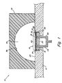
- Fig. 1 illustrates schematically, in cross-section, an electrochemical analyzer 10 according to one embodiment of the invention.
- the arrangement of components as shown in Fig. 1 is known. However, the prior art does not describe a fluoroelastomer as component 36 of Fig. 1 or as any portion that in part defines container 39.
- Analyzer 10 includes a substantially planar base, or substrate 12, and a planar-type sensor 14 in an indentation 16 of base 12 that is shaped to receive sensor 14 such that an essentially planar sensing surface 18 of the sensor is approximately flush with a surface 20 of the base.
- Sensor 14 includes a substrate 22 through which a first electrode 24 and a second electrode 26 pass.
- electrodes 24 and 26 are electrically crossed, or shorted, such that an essentially one-electrode sensor is defined.
- Sensors having any number of electrodes can include the elastomer of the invention, for example one-electrode sensors typical of ion sensors, two-electrode sensors as described in U.S. Patent No. 4,536,274, referenced above, three-electrode sensors as described in U.S. Patent No. 5,401,376, referenced above, and sensors having additional electrodes.
- An array of sensor chips can be fabricated with any particular number of electrodes. Some of the electrodes may be crossed, as illustrated in the figures, to effectively reduce the number of electrodes if desired. In this way, a single type of chip can be adapted to serve as one of several types of sensors.
- An electrolyte layer 28 coats a side of substrate 22 that faces the sensing surface 18 of the sensor, and contacts electrodes 24 and 26, and a primary membrane 30 coats electrolyte 28.
- the term "primary membrane” is meant to define any of a wide variety of membranes suitable for use in a sensor to separate a sample from an electrode, and which is adapted to facilitate determination of an analyte.
- membranes that are semipermeable to a gas such as oxygen are contemplated, as well as heterogeneous membranes such as solvent polymeric membranes or liquid membranes (discussed below).
- the primary membrane includes a first surface 32 that contacts electrolyte 28, and that is thus in electrical communication with electrodes 24 and 26, and a second surface 18 opposite surface 32 that is the sensing surface.
- Sensor 14 illustrates schematically a type of planar, solid-state sensor that is very cost-efficient to manufacture.
- a process for manufacturing such a sensor can involve fabricating many sensors on a single wafer (in which a single membrane layer on a single electrolyte layer is cast, for example), and dicing the wafer to define many individual sensors. As a result, each sensor includes peripheral edges that expose the various layers from which the sensor is fabricated. In the sensor illustrated, electrolyte 28 is exposed at the edges of the sensor. Accordingly, an adhesive 34, such as an epoxy or cyanoacrylate adhesive, can be introduced into spaces between the edge of sensor 14 and the border of indentation 16 within which sensor 14 resides. Adhesive 34 is designed to prevent components of a fluid sample from interfering with the function of electrolyte 28 and to prevent leaking from the sample container, described below.
- Analyzer 10 includes a cover 36 that, according to the embodiment illustrated, is a single-piece unit including a semispherical cavity having an interior surface 38. Cover 36, when placed upon base 12, completes a sample container 39.
- the semispherical cavity of cover 36 that defines in part container 39 has a diameter greater than the largest dimension of sensing surface 18, and is centered above sensing surface 18, thus all of sensing surface 18 defines a sensing area 40 of sensor 14 according to the embodiment illustrated.
- cover 36 is an elastomer having certain advantageous properties.
- Elastomeric material suitable for use in connection with the invention is advantageously formulated from a material which, when it defines an entire cover, a portion of a cover, or is held firmly between a cover and primary membrane to form in part a sample container (described below with reference to Fig. 3) does not compromise sensor performance (use) or shelf life as compared to a similar sensor that does not include elastomeric material.
- the elastomeric material of the invention can be used in a sensor and provides the sensor with a shelf life of at least 30 days, preferably 60 days, more preferably six months, and according to a particularly preferred embodiment at least twelve months.
- the elastomer is formulated from a durable organic polymer which does not creep or flow when stressed, which has a low durometer rating, providing a good seal such as a hermetic seal (in embodiments described below, for example), which is gas impermeable, and which may be slightly hygroscopic and thus may swell slightly in the presence of solution containing water, which in some instances will aid sealing at a membrane.
- a hermetic seal in embodiments described below, for example
- the elastomer has a hardness of less than about 100 on the Shore A scale, more preferably a hardness of from about 50 to about 90 on the Shore A scale, and most preferably a hardness of from about 65 to about 75 on the Shore A scale.
- the elastomer desirably has sub-microscopic properties which make it gas impermeable, and is thus preferably formulated from a precursor having a sufficient degree of unsaturated carbon-carbon bonds to form a sufficiently highly cross-linked polymer compound when cured, or have other means of attaining such a degree of cross-linking.
- the elastomer that defines cover 36 has low carbon dioxide and oxygen permeability.
- its permeability to carbon dioxide is desirably less than about 100 barrers, more preferably less than about 40 barrers, and most preferably less than about 20 barrers.
- Permeability values in Barrer units may be obtained according to the following method.
- Material to be tested is mounted so as to be contacted on a first side by flowing water having a partial pressure of oxygen equal to the partial pressure of oxygen in air, and contacted on a second side opposite the first side with flowing carrier gas such as nitrogen.
- carrier gas such as nitrogen.
- the areas on the first and second sides of the material contacted by water and carrier gas, respectively, are of equal dimension.
- the carrier gas flowing past the material is analyzed for oxygen content using a sensor such as a potentiometric palladium oxygen sensor.
- permeability values in Barrer units according to Equation 1 are determined.
- the solubility of carbon dioxide in the elastomer is desirably less than about 200 cm 3 (at STP)/cm 3. atm, preferably less than about 125, more preferably less than about 75 cm 3 (at STP)/cm 3. atm.
- the solubility of oxygen in the elastomer is desirably less than about 50, preferably less than about 30, and more preferably less than about 20 cm 3 (at STP)/cm 3. atm.
- the elastomer is an organic polymer
- it is fabricated so as not to contain a substantial amount of mobile extractable materials such as plasticizers that could leach into a sensor primary membrane directly, or via a fluid sample.
- mobile extractable materials such as plasticizers that could leach into a sensor primary membrane directly, or via a fluid sample.
- Such leaching of extractables can affect the microscopic physical properties of the membrane, disadvantageously effecting a change in its permeability characteristics or ionic or electrical properties. This is an especially notable consideration with respect to sensors designed for long-term use, on the order of, for example, days or months, and with respect to sensors operating with small test sample volumes.
- the elastomer should be free of any species which could migrate into a fluid sample contacting the elastomer, affecting electrochemical measurements, and/or destroying sensor components.
- Material used in the formation of elastomer is preferably selected to be essentially free of mobile transition and main group metals, especially battery metals such as iron, cobalt, nickel, lead, copper, extractables, and species such as sulfides which are deleterious to preferred electrode materials, such that electrochemical response is not affected over long-term sensor use, specifically for at least 2 days of normal sensor operation.
- battery metals such as iron, cobalt, nickel, lead, copper, extractables, and species such as sulfides which are deleterious to preferred electrode materials, such that electrochemical response is not affected over long-term sensor use, specifically for at least 2 days of normal sensor operation.
- the elastomer should be resistant to plasticizer uptake. In particular it should have less than about 10% by weight plasticizer uptake, preferably less than about 5% by weight plasticizer uptake, more preferably less than about 1% by weight plasticizer uptake.
- the elastomer should be essentially free of mobile extractables such as sulfur and hydrocarbon.
- the elastomer also should be essentially free of mobile heavy metals and alkali or alkali earth elements such as calcium, magnesium, sodium, cesium, lithium, and potassium. Oxides such as calcium oxide and zinc oxide are not particularly disadvantageous, but should be present in low concentration, if present at all, and a material containing such oxides should be tested to determine whether the oxides impart disadvantageous results.
- a simple test to screen materials that are candidates for use as the elastomer of the invention is to expose a candidate material to a particular solvent, determine the change in weight of the material before and after exposure and drying, and thereby determine the amount of material that has leached out of or into the material.
- materials can be exposed to tetrahydrofuran for several hours, dried, and weighed.
- a significant loss in weight for example a loss in weight of at least 10%, is an indication that the candidate material may contain leachables that could be detrimental for use in accordance with the invention.
- a candidate material is exposed to diundecyl phthalate and dried.
- a gain in weight of the material of greater than about 5% may indicate that the material, if placed in a sensor at a position contiguous with a membrane, may absorb species such as plasticizers from the membrane (particularly a heterogeneous membrane such as a solvent polymeric membrane or liquid membrane), detrimentally affecting the performance of the membrane.
- the elastomer of the invention should have a high electrical resistance.
- the structure formed by the material should provide wet resistance of at least 50 gigaohms and preferably at least 100 gigaohms between regions desirably electrically isolated from each other.
- wet resistance is meant to define resistance when the sensor is exposed to a fluid sample such as blood, a reference solution, or fluid such as saline introduced into the sensor for storage, and has been exposed to the fluid for a period of time equal to typical start-up and stabilization time.
- Heterogeneous membranes are especially damaging, in general, to adjacent elastomers.
- a heterogeneous membrane such as a solvent polymeric membrane or liquid membrane, is a membrane containing a mobile carrier in an inert matrix such as plasticized PVC.
- Such mobile carriers can include charged carriers such as ion-exchangers, or neutral carriers such as ionophores.
- Performance of these heterogeneous membranes is especially compromised with heretofore-known elastomers that are contiguous with such membranes, and prior art sensors have not been fabricated using heterogeneous membranes contiguous with elastomers that have gas permeability low enough for determining a gas or a species whose concentration is dependant on a gas.
- pH sensors for use with samples that contain carbon dioxide, such as blood samples are particularly difficult to use in conjunction with an elastomer contacting the sensor membrane since the concentration of the hydrogen ion, which is affected by CO 2 concentration, is measured.
- another embodiment of the invention involves an electrochemical sensor having a heterogeneous membrane such as a solvent polymeric membrane or liquid membrane and an elastomer contiguous with the membrane.
- the elastomer has a permeability to oxygen or carbon dioxide as described above with respect to the elastomer that defines cover 36.
- the elastomer material is typically formed from a highly cross-linked elastomeric compound. Any elastomeric fluoropolymer material which meets all the purity and physical requirements listed above may serve.
- a preferred embodiment of this material is a fluoropolymer-based elastomer that optionally contains one or more of additives, for example calcium hydroxide, magnesium oxide and titanium dioxide, for example, that contribute to certain desirable characteristics in the elastomer.
- additives for example calcium hydroxide, magnesium oxide and titanium dioxide, for example, that contribute to certain desirable characteristics in the elastomer.
- Suitable fluoroelastomers are described in U.S. Patent Nos. 4,743,300 (Brinduse et al .); 4,803,239 (Schaberg); 4,912,171 (Grootaart et al.
- Suitable fluoroelastomers are available from Ausimont (Morristown, New Jersey) sold under the trademark Tecnoflon; from DuPont (Wilmington, Delaware) sold under the mark Kalrez and the mark Viton; from the Minnesota Mining and Manufacturing Co. (3M), in particular a copolymer of chlorotrifluoroethylene and vinylidene fluoride sold under the mark Kel-F; and from Ethyl (Baton Rouge, Louisiana), perfluoroalkoxyphosphazene, sold under the mark Eypel F.
- a copolymer of vinylidene fluoride and hexafluoropropylene forms the basis of the elastomer
- a particularly preferred elastomeric material is a product sold as KM-2-41-2 by Cri-Tech, Inc., Hanover, Mass. which is a composition including about 71% by weight of a vinylidene fluoride-hexafluoropropylene copolymer sold under the trademark Fluorel by the Minnesota Mining and Manufacturing Co., containing about 3.2% by weight calcium hydroxide, about 3.2% by weight magnesium oxide, and about 21.2% by weight titanium dioxide.
- any of a variety of methods for forming the elastomer of the invention into a gasket, cover, or portions of a cover can be carried out, such as injection molding, compression molding, solvent casting, and the like. Curing the material via heat, UV radiation, etc. can follow. In some instances, it is desirable to carry out formulation and formation of the gasket in a sulfur-free environment.
- the fluoroelastomer used can be in a variety of forms and shapes all of which act as gas sealants for the container.
- the fluoroelastomer used is either the entire material of the container or more preferably a conventional encircling gasket having an internal space for the sensing membrane surface and an encircling gasket portion acting to seal an edge of the membrane.
- the fluoroelastomer material can be in the form of a plug to close the container after it is formed.
- Any use of a fluoroelastomer to seal the container is referred to as a "gasket" in this invention.
- Conventional gasket forms such as flat, sheet, cut, o-ring and other cross-sectional shapes can be used.
- the gaskets are preferably used in continuous encircling forms as, for example, o-rings.
- cover 36 is made of a single material, that is, an elastomer having particular advantageous properties according to the invention.
- Cover 36 can be formed, however, of a variety of materials, only one of which is an elastomer of the invention.
- the bulk of cover 36 could comprise a relatively rigid structure, such as inert plastic or ceramic, with portions of the cover that contact base 12 being elastomeric.
- the cover 36 can be of any of a variety of desirable shapes or dimensions other than the shape and dimension illustrated.
- cover 36 can be fabricated to include an interior surface 38 having topography that is advantageous in a continuous-flow sensor, or can be shaped to minimize the volume of sample container 39 in a stopped-flow arrangement where desired.
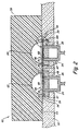
- a multi-sensor analyzer 42 is illustrated schematically in cross-section. In all of the figures, some components that are similar to various figures are represented by a single number.
- Analyzer 42 includes a first sensor 44 and a second sensor 46 in indentations 48 and 50, respectively, of a base 52.
- the sensors, base, cover member, and other components can be replaced with similarly-functioning components.
- sensors 44 and 46 are illustrated as identical to sensor 14 in Fig. 1. It is to be understood, however, that the invention resides in a particularly useful elastomer in association with an electrochemical analyzer, and methods that are enhanced via use of such an elastomer, and that sensors can be of a variety of types.
- a multi-sensor analyzer includes a sensor 44 for determining a gas and a sensor 46 for determining an ionic species.
- gas sensor includes sensors of pH in a sample containing carbon dioxide.
- determination means electrochemically sensing the presence of and/or concentration of a particular analyte in a medium brought into contact with a sensing area of a sensor, via exploitation of known electrochemical principles.
- a gas sensor 44 will include a primary membrane 54 that is a semipermeable membrane that has the requisite gas permeability properties and electrochemical properties, such as a membrane as described in U.S. Patent No 5,401,376, referenced above.
- a sensor 46 specific for an ionic species will include a primary membrane 56 such as a heterogeneous membrane, typically including an ionophore, which facilitates determination of a predetermined ion.
- Such membranes and ionophores are known to those of ordinary skill in the art, as described in International Publication No. WO 91/11710, referenced above.
- analyzer 42 includes a cover 58 that has formed therein two semispherical cavities, each centered above a sensor 44 or 46.
- cover 58 is made of the elastomer of the invention.
- the cavities of Fig. 2 are smaller in diameter than the smallest dimension across sensing surface 19 or 21 of each of primary membranes 54 and 56, respectively, thus sample containers 62 and 64 defined in part by these cavities each include a portion of sensing surface 19 or 21 of a primary membrane, the portions defined as sensing areas 66 and 68, and an interior surface of a semispherical indentation in cover 58, but do not include a portion of surface 53 of base 52.
- each of the boundaries between surface 53 of base 52 and sensing surface 19 or 21 of a sensor is bridged by the elastomer of the invention.
- Fig. 2 illustrates an arrangement that is particularly convenient and efficient to manufacture.
- first and second sensors 44 and 46 can each be manufactured, in bulk, from a diced wafer of like sensors.
- adhesive need not be applied in gaps 57 between the edges of sensors 44 and 46 and the perimeters of indentations 48 and 50 within which sensors 44 and 46 reside, respectively.
- electrodes 24 and 26 are electrochemically sealed from sensing areas 66 and 68 of the sensors by regions 60 of cover 58 that each bridge surface 53 of base 52 and sensing surface 19 or 21 of one of primary membranes 54 or 56.
- the term "electrochemical seal” is meant to define a seal that, when the sensor is exposed to a medium such as a fluid medium carrying an analyte to be determined at a sensing surface of a membrane, provides electrical resistance between an electrode within the sensor and the sensing surface of the membrane (the surface opposite the surface that is intended to be in electrical communication with the electrode), via a pathway 149 (as illustrated in connection with sensor 46) that circumvents the primary membrane, that is at least twice, preferably about five times, and more preferably about ten times the electrical resistance across the primary membrane.
- cover 58 can be made entirely of the elastomer of the invention.
- cover 58 can be made of more rigid plastic or ceramic, with regions 60 of cover 58 that each bridge surface 53 of base 52 and sensing surface 19 or 21 of one of primary membranes 54 or 56, being made of the elastomer of the invention.
- cover 58 can include elastomeric portions anywhere so long as the elastomeric portions seal sensing areas 66 and 68 electrochemically from electrodes 24 and/or 26.
- an arrangement can include a cover 58 that is relatively rigid, with a gasket that is made of the elastomer of the invention placed between cover 58 and portions of sensing surfaces in register therewith so as to define an isolated sensing area 66 or 68 on primary membranes 54 or 56 adapted to receive a sample. That is, a sensing area can be created that is of any area less than or equal to the area of the sensing surface of a primary membrane with use of the elastomer of the invention, and additional sealing of the edges of the sensors (additional isolation of the sensor electrodes or electrolyte from the sample area), for example with adhesive, is not required.
- electrochemical seal is defined above, and a further definition of this term in accordance with the invention, with reference to Fig. 2, includes a seal formed between electrodes, or electrolyte 28 of adjacent sensors 44 and 46. That is, where a sensor electrode or electrolyte (or other component that is in electrical communication with an sensor electrode) is not electrically insulated from a like component of a sensor in the same analyzer, the elastomer of the invention can electrochemically seal the components of the neighboring sensors from each other.
- a pathway 147 between electrolyte 28 of adjacent sensors has a resistance at least twice, preferably five times, and more preferably at least ten times as great as the resistance across one of the primary membranes of the analyzer.
- the wet resistance between electrodes of adjacent sensors is at least 50 gigaohms, preferably at least 100 gigaohms.
- Sensors 44 and 46 can be constructed and arranged to determine a single analyte, or different analytes.
- sensor 44 is constructed and arranged for determining a gas such as carbon dioxide or oxygen (or gas-dependant species such as pH in the presence of the gas to which it is sensitive), and sensor 46 is constructed and arranged for determining an ionic species such as sodium ion, potassium ion, chloride ion, or calcium ion.
- the elastomer of the invention allows for the manufacture of an analyzer that contains such sensors together, preferably addressed by a single sample container, in which the electrodes of the sensors are electrochemically sealed from each other solely by the elastomer. The electrochemical seal is adequate to allow stopped-flow analysis in such an analyzer.
- sample container 62 and sample container 64 can be interconnected, thus defining in essence a single container.
- a stopped-flow analyzer can include an injector adapted to inject a metered dose of fluid sample in an amount essentially equal to the volume of the container that is a combination of container 62 and 64, or a slightly larger volume if required for stopped-flow analysis by the analyzer. This will minimize the volume of sample consumed.
- the analyzer also can include a mechanism constructed and arranged to determine both the gas analyte at sensor 44 and the ionic species analyte at sensor 46 while a sample is positioned at sensing areas 66 and 68 and is prevented from flowing.
- Such a mechanism can include a sensor that is triggered by the injection of a fucid sample into the containers and the completion of such injection, and automatically carries out electrochemical measurements that determine the gaseous analyte at sensor 44 and the ionic species analyte at sensor 46. These mechanisms are known.
- the elastomer of the invention comprises an entire cover that defines a container for providing a sample in contact with a sensing area of a sensor, or comprises any portion of such a cover, and according to a preferred embodiment comprises a gasket between a somewhat rigid and inert cover and a base or, according to a particularly preferred embodiment, a primary membrane of a sensor.
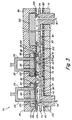
- an electrochemical analyzer 70 is illustrated schematically in cross section which can include any number of sensors, can provide for continuous-flow or stopped-flow analysis, and can be manufactured very efficiently using sensors made from diced wafers of a plurality of like sensors, electrochemically sealed using solely the elastomer as gasket material.
- Analyzer 70 includes a metal heater plate 72 for maintaining constant and stable temperature of a fluid sample to be analyzed.
- a flow cell 74 constructed of inert plastic or ceramic includes a sample inlet 76 at a first end in fluid communication with a sample outlet 78 at a second end.
- the flow cell includes a substantially planar portion between the sample inlet and outlet, and a series of holes 77, 79, 81, and 83 through the planar portion through which fluid sample can flow from one side of the essentially planar flow cell to the other.
- a crossover gasket 80 resides between heater plate 72 and flow cell 74, the flow cell spaced from the crossover gasket by way of a plurality of downwardly-depending protrusions 84 on the flow cell.
- Downwardly-depending protrusions 84 form fluid seals at crossover gasket 80 such that fluid sample can reside between flow cell 74 and crossover gasket 80 and between adjacent protrusions 84 without leaking.
- An optional fluid sealer made of electrically insulative material can be placed between crossover gasket 80 and heater plate 72 so that, in the event of any leakage, no electrical shortage can occur via heater plate 72.
- Crossover gasket 80 can be made of the elastomer of the invention, or any material or combination of materials that does not adversely affect a fluid sample and that provides for fluid seals at protrusions 84.
- a base 86 that, similar to bases 12 and 52 of Figs. 1 and 2, respectively, includes indentations 88 and 90 that carry sensors 92 and 94, respectively, and an optional preheater chip 102.
- Sensors 92 and 94 like sensors described above, include electrodes 24 and 26, electrolyte 28, and primary membranes 96 and 98, respectively.
- Primary membranes 96 and 98 have respective surfaces 103 and 105 that are in electrical communication with sensor electrodes, and opposing sensing surfaces 104 and 106.
- Sensor 92 is adapted to determine a gas such as carbon dioxide or oxygen (or pH in a sample containing CO 2 ), and sensor 94 is adapted for determining an ionic species, as described above, although any combination of sensors can be used.
- a gas such as carbon dioxide or oxygen (or pH in a sample containing CO 2 )
- sensor 94 is adapted for determining an ionic species, as described above, although any combination of sensors can be used.
- a sensor gasket 108 comprising the elastomer of the invention, is positioned between flow cell 74 and base 86, and is urged upwardly by upwardly-depending protrusions 100 of flow cell 74 against sensing surface 104 of sensor 92 and sensing surface 106 of sensor 94, defining sensing areas 112 and 114, respectively, of sensing surfaces 104 and 106.
- Sensor gasket 108 forms, in each sensor, an electrochemical seal between a sensor electrode of each sensor and a fluid sample contacting the sensing area of each sensor, and between electrodes (electrolytes) of adjacent sensors.
- a gasket, or a plurality of gaskets can be positioned only where needed to provide seals at primary membranes as illustrated in connection with gasket portions 110 at edges of sensors 92 and 94 or, according to another embodiment that can be easier to manufacture, a gasket including a continuous portion (such as 109) can contact primary membranes of adjacent sensors.
- a gasket including a continuous portion such as 109 can contact primary membranes of adjacent sensors.
- Sensor gasket 108 seals the entire perimeter of each of sensors 92 and 94 at primary membranes 96 and 98, respectively.
- sensor gasket 108 can be interconnected, as a single continuous portion, or can be individually fabricated as individual gasket portions.
- Continuous portion in this context means a single piece of elastomeric material, containing whatever holes or cut-outs are necessary to provide sealing at desired locations. According to a preferred embodiment, a single, continuous gasket is provided for purposes of simplicity.
- Flow cell 74 includes a plurality of upwardly-depending protrusions 100 that maintain the sensors and base in spaced relation from the planar section of the flow cell. Accordingly, regions between protrusions 100, the flow cell planar section, and the sensors or base 86 can contain fluid.
- a liquid sample can enter analyzer 70 through sample inlet 76, pass into a region above the planar section of flow cell 74 defined by the flow cell, upwardly-depending protrusion 100, a preheater chip 102 that allows the sample to reach a stable temperature, and sensor gasket, can pass downwardly through a hole 83 in the flow cell into a section below the planar section of the cell defined by the flow cell, downwardly-depending protrusions 84, and crossover gasket 80, can pass upwardly through a hole 81 in the flow cell into a section defined by the planar section of the cell, upwardly-depending protrusions 100, sensing surface 104 of sensor 92, and sensor gasket 108, pass downwardly through a hole 79 into a region defined by the flow cell, downwardly-depending protrusions 84, and crossover gasket 80, and finally pass upwardly through a hole 77 into a region defined by the flow cell, upwardly-depending protrusion 100, sensing surface
- container is meant to define portions of an analyzer that hold a sample in contact with a sensing area of a sensor membrane.
- the container is defined by the interior surface 38 of cover 36, portions of surface 20 of base 12 that are not covered by cover 36, sensing surface 18 of primary membrane 30, and portions of adhesive 34 that are exposed to the sample.
- sample container 62 includes the interior surface of cover 58 at sensor 44, and sensing area 66 of sensing surface 19 of primary membrane 54. Referring to Fig.
- the sample container includes all portions that border the flow path illustrated between inlet 76 and outlet 78, including flow cell 74, protrusions 84 and 100, preheater chip 102, sensor gasket 108, crossover gasket 80, and sensing surfaces 112 and 114 of sensors 92 and 94, respectively.
- electrochemical analyzers that can include both diced (exposing electrolyte at edges thereof) gas sensors and diced ionic species sensors in a single array, the sensors sealed electrochemically with a single elastomeric material. As discussed, this facilitates methods involving stopped-flow determination of both a gas and an ionic species with a highly-efficiently manufactured analyzer.
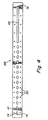
- a top view of sensor gasket 108 fabricated to fit the analyzer of Fig. 3, is illustrated.
- the gasket includes several cut-outs, and reference numerals refer to components of the analyzer of Fig. 3 that align with certain of these cut-outs.
- sample inlet 76 is illustrated at the right of the gasket, leading into a pathway that provides for sample flow against preheater chip 102.
- Sensing areas 112 and 114 of sensors 92 and 94, respectively, are defined by oval cut-outs of sensor gasket 108, as illustrated.
- Sample outlet 78 is aligned with an edge of sensing area 114.
- upwardly-depending protrusions 100 represent portions of oval protrusions sized to isolate sensing areas 112 and 114 of sensors 92 and 94 by compressing the perimeters of the oval cut-outs illustrated in Fig. 4 against the sensing surfaces 104 and 106 of sensors 92 and 94.
- Cut-outs 150 surround guide protrusions (not shown in Fig. 3) that position the gasket appropriately.
- Sensors illustrated in connection with the present invention all are similar in construction to sensor 14. However, while such solid-state, planar-type electrochemical sensors are illustrated, those of ordinary skill in the art recognize that any of a variety of electrochemical sensors that are adapted for determining one or more analytes in a sample can be used in accordance with the invention. These include, without limitation, amperometric or voltammetric, one-electrode or multi-electrode sensors that can include solid, liquid or gel electrolytes. Electrodes, electrolytes, membranes, and other components of sensors that are suitable for use in connection with the invention are described in the above-referenced documents.
- any thick-film or thin-film technique in planar sensor fabrication can be utilized.
- Voltammetric and amperometric sensors including any number of electrodes can be utilized.
- sensors that are constructed and arranged to determine the particular gases or ionic species listed herein can be expanded to determination of other analytes.
- the particular analyte determined is not per se important in the context of the present invention, but it is the different primary membranes that are required for determination of the different types of analytes that, in a single analyzer, present the challenge that is met by the present invention.
- a fluoroelastomer sheet approximately 0.038 cms (0.015 inches) thick was formed, and cut into a desired shape for use as a sensor gasket, as follows. Bulk slabs of fluoroelastomer sold by Cri-Tech, Inc., Hanover, Mass, as KM2-41-2 were formed in a thermoset mold into sheets approximately 0.038 cms (0.015 inches) thick, approximately 2.54 cms (1 inches) wide, and approximately 12.7 cms (5 inches) long.
- Molding was carried out at 180°C, -527 kg/sq.cm (7500 psi), for 11 minutes. The material was post-cured at 232°C for 16 hours. Using water-jet cutting technology, gaskets of the geometry of Fig. 4 were cut (of course, gaskets of any geometry can be formed by this or by more conventional methods such as molding).
- Planar pH sensors were fabricated as follows. A plurality of ion-selective sensors were fabricated by screen printing a plurality of individual electrodes on a laserscored ceramic wafer, and following the deposition of an ion-selective membrane, the wafer was singulated on the laser score lines so as to create a plurality of individual sensor chips. For the purpose of simplicity in this example, procedures will be described as if a single chip were fabricated.
- a sensor was fabricated a follows: An ion-selective sensor base chip was fabricated on a 0.180 cm x 0.180 inch electrically insulating alumina composite substrate, available from Coors Ceramic Company, Grand Junction, Colorado. The laser score process needed for wafer singulation is available from Lasereliance Technologies, Altamonte Springs, Florida. Holes were laser drilled through the ceramic substrate and filled with electrically conductive metallic paste (gold). Using the thick-film deposition technique, a conductive strip was fabricated on the contact side of the chip (gold) by screen printing to be in electrical contact with the metal conductor in the laser drilled hole. Suitable conductive pastes are available from Metech Company of Elverson, Pennsylvania.
- Another conductive strip was fabricated on the opposite side (electrode side) of the ceramic to be in electrical contact with the metal conductor in the hole.
- the conductive strip was fabricated so as to create an oval electrode with the approximate dimensions of 1.52 mm x 0.762 mm.
- Metal pastes were cured per manufacturer's recommendations. In this fashion, electrodes were formed through the substrate, so as to achieve back-side contact. However, as discussed above, any sensor arrangement including front-side electrode contact, can be employed.
- a dielectric (glass) passivation then was printed over the conductor on the electrode side with an opening so as to define an active electrode area.
- the silver electrodes then were galvanostatically plated with silver chloride from 0.1 m KCl for 10 minutes at -5.00 mA.
- the chip was rinsed in deionized water and air dried.
- An electrolyte was formed as follows, a 1% aqueous solution of gelatin was prepared. A buffer including 1 M citric acid, 2.73 M NaOH and 0.01 M NaCl was prepared.
- the buffered gelatin electrolyte had a pH of approximately 5.5. 200 microliters of the buffer was mixed with 10 ml of the gelatin solution. 1.52 ml of this mixture was solvent cast on the 100-sensor wafer described above, and allowed to evaporate at 80 degrees C.
- a membrane selective for hydrogen ion was fabricated.
- a 10% by weight membrane solution was prepared in THF containing 2 weight % tridodecylamine, 0.4 weight % potassium tetrakis (4-chlorophenyl) borate, 65 weight % dioctylphthalate, and 33 weight % PVC.
- a volume of 1.2 ml of membrane solution was solvent cast onto a 100-sensor wafer. The layer was dried at room temperature in a THF environment for about 24 hours. Final membrane thickness was approximately 40 ⁇ m (microns).
- the chips were diced, to define a plurality of individual pH sensors.
- Aqueous samples tonometered with clinical levels of CO 2 were measured with high pH precision and accuracy using an analyzer as described in Example 3, with a 130 second stopped-flow protocol. Sensor drifts with CO 2 tonometered samples were -0.002 mV/min. Using a 130 second stopped-flow measurement protocol, precisions below 0.008 pH units and accuracies better than 0.02 pH units were achieved. Adequate gas impermeability was demonstrated since pH sample integrity is strongly affected by any CO 2 losses through the gasket. Furthermore, no significant deterioration in sensor performance was observed over 30 days of continuous use. This demonstrates excellent chemical compatibility of the fluoroelastomer with the plasticized polymeric sensor membrane.
Claims (29)
- Analyseur électrochimique caractérisé en ce qu'il comprend :un détecteur électrochimique ayant une surface, une partie de la surface définissant une zone de détection ; etun récipient d'échantillon adapté pour placer un échantillon à la zone de détection, au moins une partie du récipient étant défini par un polymère fluoré élastomère.
- Analyseur selon la revendication 1, qui comprend :un détecteur électrochimique comprenant une membrane hétérogène ayant une surface, une partie de la surface étant adaptée pour recevoir un échantillon pour analyse électrochimique ; etun récipient d'échantillon adapté pour placer un échantillon à la zone de détection, une partie du récipient d'échantillon comprenant un élastomère essentiellement imperméable aux gaz contigu avec la membrane hétérogène.
- Analyseur selon la revendication 1, qui est destiné à doser un analyte présent dans un fluide et qui comprend une membrane de détection primaire placée au contact du fluide et un récipient imperméable renfermant au moins une partie de la membrane, le récipient étant scellé par un joint d'étanchéité en polymère fluoré élastomère.
- Analyseur selon la revendication 1, qui comprend :un premier détecteur électrochimique pour doser un gaz, le premier détecteur comprenant une première membrane primaire ayant une première zone de détection, et un récipient adapté pour placer un échantillon susceptible de contenir le gaz à la première zone de détection et défini au moins en partie par la première membrane primaire et un élastomère qui est contigu avec la première membrane primaire ; etun second détecteur électrochimique pour doser une espèce ionique, le second détecteur comprenant une seconde membrane primaire ayant une seconde zone de détection, et un récipient adapté pour placer un échantillon susceptible de contenir l'espèce ionique à la seconde zone de détection et défini au moins en partie par la seconde membrane primaire et un élastomère, qui est essentiellement le même que l'élastomère contigu avec la première membrane, qui est contigu avec la seconde membrane primaire.
- Analyseur selon l'une quelconque des revendications 1 à 4, dans lequel l'élastomère comprend un copolymère fluorure de vinylidène-hexafluoropropylène.
- Analyseur selon la revendication 1 ou la revendication 5, dans lequel le détecteur comprend une première membrane primaire, dont une partie définit la zone de détection, et le polymère fluoré élastomère est contigu avec la première membrane primaire.
- Analyseur selon la revendication 6, qui comprend en outre un second détecteur électrochimique comprenant une seconde membrane primaire, dont une partie définit une seconde zone de détection, et le polymère fluoré élastomère est contigu avec la seconde membrane primaire.
- Analyseur selon la revendication 7, dans lequel les première et seconde membranes primaires sont chacune en contact avec une partie continue de polymère fluoré élastomère.
- Analyseur selon l'une quelconque des revendications 6 à 8, dans lequel le récipient d'échantillon comprend un couvercle adapté pour recevoir un échantillon fluide, et le polymère fluoré élastomère est un joint entre le couvercle et une surface de détection de la première membrane primaire.
- Analyseur selon la revendication 9, dans lequel le détecteur comprend une électrode en communication électrique avec une surface de la première membrane primaire à l'opposé de la surface de détection et le joint forme un joint électrochimique entre l'électrode et la surface de détection, le joint formant de préférence un joint électrochimique fournissant une résistance électrique à l'état mouillé entre l'électrode et la surface de détection de la première membrane primaire par un chemin qui évite la membrane, qui est au moins le double de la résistance à l'état mouillé à travers la membrane.
- Analyseur selon l'une quelconque des revendications 1 ou 5 à 10, dans lequel le détecteur comprend une première membrane primaire ayant une première surface en communication électrique avec une électrode et une surface de détection à l'opposé de la première surface, dont une partie définit en partie la zone de détection, le polymère fluoré élastomère formant un joint électrochimique entre l'électrode et la surface de détection de la première membrane primaire.
- Analyseur selon la revendication 11, qui comprend en outre un second détecteur électrochimique comprenant une seconde membrane primaire ayant une première surface en communication électrique avec une seconde électrode et une surface de détection à l'opposé de la première surface, dont une partie définit en partie une seconde zone de détection, le polymère fluoré élastomère formant un joint électrochimique entre la seconde électrode et la surface de détection de la seconde membrane primaire, de préférence une partie continue de l'élastomère formant le joint électrochimique au premier détecteur et le joint électrochimique au second détecteur.
- Analyseur selon l'une quelconque des revendications 1 ou 5 à 12, dans lequel le récipient d'échantillon est adapté pour placer un échantillon fluide à la zone de détection de la première membrane primaire et à la seconde zone de détection, et l'analyseur comprenant en outre un injecteur adapté pour injecter une dose mesurée d'échantillon fluide dans le récipient en une quantité essentiellement non supérieure à celle requise pour l'analyse en flux stoppé aux premier et second détecteurs.
- Analyseur selon l'une quelconque des revendications 7 à 13, qui comprend en outre un mécanisme de détection pour doser plusieurs analytes pendant qu'un échantillon est placé à la zone de détection du premier détecteur et la zone de détection du second détecteur et est empêché de s'écouler.
- Analyseur selon la revendication 3, dans lequel le joint est un joint continu encerclant une partie de la membrane primaire définissant une surface de détection.
- Analyseur selon la revendication 3 ou la revendication 15, dans lequel le joint a une dureté Shore A entre 10 et 100.
- Analyseur selon l'une quelconque des revendications 3, 15 ou 16, dans lequel le joint forme un joint électrochimique fournissant une résistance électrique à l'état mouillé entre une électrode de l'analyseur et une surface de détection de la membrane primaire par un chemin qui évite la membrane, qui est au moins le double de la résistance à l'état mouillé à travers la membrane.
- Analyseur selon l'une quelconque des revendications 3 ou 15 à 17, dans lequel la perméabilité du joint au dioxyde de carbone est inférieure à 100 barrers ou la perméabilité du joint à l'oxygène est inférieure à 20 barrers.
- Analyseur selon l'une quelconque des revendications 3 ou 15 à 18, dans lequel le joint forme un joint à travers lequel le passage d'un fluide et d'un gaz est essentiellement barré de sorte que l'essai peut se poursuivre pendant une période d'au moins deux jours sous un fonctionnement normal du détecteur.
- Analyseur selon l'une quelconque des revendications 3 à 15 ou 19, qui est destiné à doser un gaz ou un analyte, dont le dosage dépend du gaz présent dans le fluide, et le récipient est scellé contre la perméabilité à un gaz par le joint.
- Analyseur selon la revendication 4 ou la revendication 5, dans lequel une partie continue d'un élastomère est contiguë avec la première membrane primaire et avec la seconde membrane primaire.
- Analyseur selon l'une quelconque des revendications 4, 5 ou 21, dans lequel le récipient du premier détecteur et le récipient du second détecteur sont continus, et les élastomères contigus avec les première et seconde membranes primaires forment des joints formant des joints de fluide entre un couvercle adapté pour recevoir un échantillon fluide et les première et seconde membranes primaires, respectivement.
- Analyseur selon l'une quelconque des revendications 4, 5, 21 ou 22, dans lequel le premier détecteur électrochimique comprend une première électrode en communication électrique avec une surface de la première membrane primaire à l'opposé de la surface contiguë avec l'élastomère, l'élastomère formant un joint électrochimique entre la première électrode et la surface de la première membrane contiguë avec l'élastomère, et le second détecteur électrochimique comprend une seconde électrode en communication électrique avec une surface de la seconde membrane primaire à l'opposé de la surface contiguë avec l'élastomère, l'élastomère formant un joint électrochimique entre la seconde électrode et la surface de la seconde membrane contiguë avec l'élastomère.
- Analyseur selon l'une quelconque des revendications 4, 5 ou 21 à 23, dans lequel la résistance électrique à l'état mouillé à travers l'élastomère entre la première électrode et la surface de la première membrane primaire contiguë avec l'élastomère est d'au moins 50 gigaohms, et la résistance électrique à travers l'élastomère entre la seconde électrode et la surface de la seconde membrane primaire contiguë avec l'élastomère est d'au moins 50 gigaohms.
- Analyseur selon l'une quelconque des revendications 4, 5 ou 21 à 24, dans lequel le gaz est l'oxygène ou le dioxyde de carbone et l'espèce ionique est l'ion sodium, l'ion potassium, l'ion chlorure ou l'ion calcium.
- Analyseur selon l'une quelconque des revendications 4, 5 ou 21 à 25, dans lequel le premier détecteur électrochimique comprend la première membrane primaire ayant une première surface en communication électrique avec une première électrode et une surface de détection à l'opposé de la première surface, dont une partie définit en partie la première zone de détection, et le second détecteur électrochimique comprend la seconde membrane primaire ayant une première surface en communication électrique avec une seconde électrode et une surface de détection à l'opposé de la première surface, dont une partie définit en partie la seconde zone de détection, l'élastomère formant un joint électrochimique entre la première électrode et la surface de détection de la première membrane primaire et un joint électrochimique entre la seconde électrode et la surface de détection de la seconde membrane primaire.
- Analyseur selon l'une quelconque des revendications 4, 5 ou 21 à 26, dans lequel le récipient d'échantillon est adapté pour placer un échantillon fluide à la zone de détection de la première membrane primaire et à la seconde zone de détection, et l'analyseur comprenant en outre un injecteur adapté pour injecter une dose mesurée d'échantillon fluide dans le récipient en une quantité essentiellement non supérieure à celle requise pour l'analyse en flux stoppé à la zone de détection de la première membrane primaire et à la seconde zone de détection.
- Analyseur selon l'une quelconque des revendications 4, 5 ou 21 à 27, qui comprend en outre un mécanisme de détection pour doser plusieurs analytes pendant qu'un échantillon est placé à la zone de détection du premier détecteur et la zone de détection du second détecteur et est empêché de s'écouler.
- Procédé d'analyse électrochimique, caractérisé en ce qu'il comprend la délivrance d'un échantillon susceptible de contenir un analyte dans un analyseur tel que revendiqué dans l'une quelconque des revendications 1 à 28.
Applications Claiming Priority (2)
| Application Number | Priority Date | Filing Date | Title |
|---|---|---|---|
| US08/550,884 US5700360A (en) | 1995-10-31 | 1995-10-31 | Fluoroelastomer gasket for blood sensors |
| US550884 | 1995-10-31 |
Publications (3)
| Publication Number | Publication Date |
|---|---|
| EP0772043A2 EP0772043A2 (fr) | 1997-05-07 |
| EP0772043A3 EP0772043A3 (fr) | 1998-04-22 |
| EP0772043B1 true EP0772043B1 (fr) | 2004-09-22 |
Family
ID=24198970
Family Applications (1)
| Application Number | Title | Priority Date | Filing Date |
|---|---|---|---|
| EP96307806A Expired - Lifetime EP0772043B1 (fr) | 1995-10-31 | 1996-10-29 | Joint en fluoroélastomère pour capteurs d'analytes dans le sang |
Country Status (12)
| Country | Link |
|---|---|
| US (1) | US5700360A (fr) |
| EP (1) | EP0772043B1 (fr) |
| JP (1) | JP3964486B2 (fr) |
| KR (1) | KR970022305A (fr) |
| AT (1) | ATE277347T1 (fr) |
| AU (1) | AU6081496A (fr) |
| CA (1) | CA2184152A1 (fr) |
| DE (1) | DE69633431T2 (fr) |
| DK (1) | DK0772043T3 (fr) |
| ES (1) | ES2227572T3 (fr) |
| MX (1) | MX9603648A (fr) |
| PL (1) | PL316188A1 (fr) |
Families Citing this family (17)
| Publication number | Priority date | Publication date | Assignee | Title |
|---|---|---|---|---|
| US6123820A (en) * | 1998-06-05 | 2000-09-26 | Grupo Ch-Werfen, S.A. | Sensor cartridges |
| US6444106B1 (en) | 1999-07-09 | 2002-09-03 | Orchid Biosciences, Inc. | Method of moving fluid in a microfluidic device |
| DE10134140C1 (de) * | 2001-07-13 | 2003-01-30 | Draegerwerk Ag | Strömungsspalt-Begasungsadapter für einen elektrochemischen Gassensor |
| JP3625448B2 (ja) * | 2002-01-11 | 2005-03-02 | 株式会社日立ハイテクノロジーズ | イオンセンサ及びそれを用いた生化学自動分析装置 |
| US7101472B2 (en) * | 2002-03-13 | 2006-09-05 | The Charles Stark Draper Laboratory, Inc. | Microfluidic ion-selective electrode sensor system |
| US7407570B2 (en) * | 2002-03-13 | 2008-08-05 | The Charles Stark Draper Laboratory, Inc. | Disposable, self-administered electrolyte test |
| DE10353938A1 (de) * | 2003-11-18 | 2005-06-23 | Fresenius Medical Care Deutschland Gmbh | Sensorkarte zur Bestimmung von Analyten in Flüssigkeits- oder Gasproben und Verfahren zur Herstellung einer solchen Sensorkarte |
| DE102008040155A1 (de) * | 2008-07-03 | 2010-01-07 | Robert Bosch Gmbh | Sensorgehäusedeckel und Verfahren zur Herstellung eines solchen Sensorgehäusedeckels |
| US7793550B2 (en) | 2008-08-25 | 2010-09-14 | Infineon Technologies Ag | Sensor device including two sensors embedded in a mold material |
| DE102009043228A1 (de) * | 2009-02-04 | 2010-09-02 | Siemens Aktiengesellschaft | Anordnung und Verfahren zum elektrochemischen Messen von biochemischen Reaktionen sowie Herstellungsverfahren der Anordnung |
| US9448198B2 (en) * | 2011-07-05 | 2016-09-20 | Stmicroelectronics Pte Ltd. | Microsensor with integrated temperature control |
| WO2017120464A1 (fr) * | 2016-01-08 | 2017-07-13 | Siemens Healthcare Diagnostics Inc. | Élément chauffant pour réseau de capteurs |
| US10359391B2 (en) | 2016-07-07 | 2019-07-23 | e-SENS, Inc. | Sensor with a membrane having full circumferential adhesion |
| EP3559664B1 (fr) * | 2016-12-23 | 2020-12-09 | Radiometer Medical ApS | Ensemble capteur multi-usage pour liquides corporels |
| US10464063B2 (en) | 2017-04-07 | 2019-11-05 | e-SENS, Inc. | Microfluidics chip with sensor die clamping structures |
| US10710068B2 (en) | 2017-09-20 | 2020-07-14 | e-SENSE, Inc. | Microfluidic chip with chemical sensor having back-side contacts |
| US11022511B2 (en) | 2018-04-18 | 2021-06-01 | Aron Kain | Sensor commonality platform using multi-discipline adaptable sensors for customizable applications |
Family Cites Families (21)
| Publication number | Priority date | Publication date | Assignee | Title |
|---|---|---|---|---|
| US4225410A (en) * | 1978-12-04 | 1980-09-30 | Technicon Instruments Corporation | Integrated array of electrochemical sensors |
| US4534356A (en) * | 1982-07-30 | 1985-08-13 | Diamond Shamrock Chemicals Company | Solid state transcutaneous blood gas sensors |
| US4571292A (en) | 1982-08-12 | 1986-02-18 | Case Western Reserve University | Apparatus for electrochemical measurements |
| US4454007A (en) | 1983-01-27 | 1984-06-12 | E. I. Du Pont De Nemours And Company | Ion-selective layered sensor and methods of making and using the same |
| US4536274A (en) | 1983-04-18 | 1985-08-20 | Diamond Shamrock Chemicals Company | pH and CO2 sensing device and method of making the same |
| US4734184A (en) * | 1985-08-29 | 1988-03-29 | Diamond Sensor Systems, Inc. | Self-activating hydratable solid-state electrode apparatus |
| US4743300A (en) * | 1986-08-29 | 1988-05-10 | Minnesota Mining And Manufacturing Company | Polyfluoropolyethers having pendant perfluoroalkoxy groups |
| US4871439A (en) * | 1987-02-05 | 1989-10-03 | Steven Enzer | Disposable self-calibratable electrode package |
| US4874500A (en) * | 1987-07-15 | 1989-10-17 | Sri International | Microelectrochemical sensor and sensor array |
| US4803239A (en) * | 1987-09-14 | 1989-02-07 | Minnesota Mining And Manufacturing Company | Fluorocarbon elastomer articles having improved amine resistance |
| DK556488A (da) * | 1987-10-05 | 1989-04-06 | Arden Medical Systems Inc | Foeler til maaling af enzymhydrogenerbare/dehydrogenerbare kemiske komponenter i vandige oploesninger |
| US4912171A (en) * | 1988-04-01 | 1990-03-27 | Minnesota Mining And Manufacturing Company | Fluoroelastomer curing process with phosphonium compound |
| US4908112A (en) * | 1988-06-16 | 1990-03-13 | E. I. Du Pont De Nemours & Co. | Silicon semiconductor wafer for analyzing micronic biological samples |
| CA1316572C (fr) * | 1988-07-18 | 1993-04-20 | Martin J. Patko | Senseur electrochimique, jetable, pre-etalonne |
| US4985520A (en) * | 1988-07-29 | 1991-01-15 | Asahi Kasei Kogyo Kabushiki Kaisha | Fluoroelastomer having excellent processability |
| US5371143A (en) * | 1989-11-16 | 1994-12-06 | Minnesota Mining And Manufacturing Company | Polymer blend composition of fluorinated elastomers, thermoplastic polymers and thermoplastics elastomers |
| US5183549A (en) * | 1990-01-26 | 1993-02-02 | Commtech International Management Corporation | Multi-analyte sensing electrolytic cell |
| US5266650A (en) * | 1990-10-11 | 1993-11-30 | Minnesota Mining And Manufacturing Company | Curing fluorocarbon elastomers |
| US5284568A (en) * | 1992-07-17 | 1994-02-08 | E. I. Du Pont De Nemours And Company | Disposable cartridge for ion selective electrode sensors |
| US5547555A (en) * | 1993-02-22 | 1996-08-20 | Ohmicron Technology, Inc. | Electrochemical sensor cartridge |
| US5387329A (en) * | 1993-04-09 | 1995-02-07 | Ciba Corning Diagnostics Corp. | Extended use planar sensors |
-
1995
- 1995-10-31 US US08/550,884 patent/US5700360A/en not_active Expired - Lifetime
-
1996
- 1996-07-31 AU AU60814/96A patent/AU6081496A/en not_active Abandoned
- 1996-08-26 MX MX9603648A patent/MX9603648A/es not_active IP Right Cessation
- 1996-08-26 CA CA002184152A patent/CA2184152A1/fr not_active Abandoned
- 1996-09-20 PL PL96316188A patent/PL316188A1/xx unknown
- 1996-10-29 EP EP96307806A patent/EP0772043B1/fr not_active Expired - Lifetime
- 1996-10-29 ES ES96307806T patent/ES2227572T3/es not_active Expired - Lifetime
- 1996-10-29 AT AT96307806T patent/ATE277347T1/de not_active IP Right Cessation
- 1996-10-29 DK DK96307806T patent/DK0772043T3/da active
- 1996-10-29 DE DE69633431T patent/DE69633431T2/de not_active Expired - Lifetime
- 1996-10-30 KR KR1019960051630A patent/KR970022305A/ko not_active Application Discontinuation
- 1996-10-31 JP JP28988296A patent/JP3964486B2/ja not_active Expired - Fee Related
Also Published As
| Publication number | Publication date |
|---|---|
| ATE277347T1 (de) | 2004-10-15 |
| DE69633431D1 (de) | 2004-10-28 |
| ES2227572T3 (es) | 2005-04-01 |
| EP0772043A2 (fr) | 1997-05-07 |
| DE69633431T2 (de) | 2005-10-13 |
| JPH09166570A (ja) | 1997-06-24 |
| MX9603648A (es) | 1997-04-30 |
| CA2184152A1 (fr) | 1997-05-01 |
| JP3964486B2 (ja) | 2007-08-22 |
| EP0772043A3 (fr) | 1998-04-22 |
| US5700360A (en) | 1997-12-23 |
| KR970022305A (ko) | 1997-05-28 |
| PL316188A1 (en) | 1997-05-12 |
| DK0772043T3 (da) | 2004-12-27 |
| AU6081496A (en) | 1997-05-08 |
Similar Documents
| Publication | Publication Date | Title |
|---|---|---|
| EP0772043B1 (fr) | Joint en fluoroélastomère pour capteurs d'analytes dans le sang | |
| US4874500A (en) | Microelectrochemical sensor and sensor array | |
| EP0608872B1 (fr) | Electrode sélective des ions à détection de courant opérant à sec | |
| US6123820A (en) | Sensor cartridges | |
| EP0625704B1 (fr) | Détecteurs planaires d'oxygène à électrolyte solide | |
| US5338429A (en) | Electrochemical toxic gas sensor | |
| EP0151197A1 (fr) | Demi-cellule sélective d'ions à plusieurs couches | |
| KR100358933B1 (ko) | 평면형 기준 전극 | |
| EP0064337B1 (fr) | Mesure du bioxyde de carbone | |
| Tsukada et al. | An integrated chemical sensor with multiple ion and gas sensors | |
| US6001240A (en) | Electrochemical detection of hydrogen cyanide | |
| EP0512070A1 (fr) | Cellule electrolytique de detection d'analytes multiples | |
| KR20000061275A (ko) | 자기 진단기능을 갖는 소형 고체상 기준전극 | |
| EP1939614B1 (fr) | Capteur d'ions et module de capteur d'ions | |
| AU2009248158A1 (en) | Electrochemical sensor with diffusion labyrinth | |
| US5384031A (en) | Reference electrode | |
| WO1997034142A1 (fr) | Capteur electrochimique a systeme d'electrolyte non aqueux | |
| CN100462718C (zh) | 用于分离电化学传感器内电解质室的装置 | |
| CA2648355C (fr) | Capteur d'oxygene | |
| JP2001514760A (ja) | サブミニアチュアスルーホールを備えたワイアリングサブストレートの製造方法 | |
| WO2005015195A1 (fr) | Capteur de gaz electrochimique | |
| WO1999001758A1 (fr) | Detecteur electrochimique destine a detecter du chlorure d'hydrogene et son procede d'utilisation | |
| RU2537094C1 (ru) | Проточная мультисенсорная потенциометрическая ячейка для анализа малых объемов жидких образцов | |
| US20030024812A1 (en) | Solid-state reference electrode system | |
| Birch et al. | Potentiometric transducers |
Legal Events
| Date | Code | Title | Description |
|---|---|---|---|
| PUAI | Public reference made under article 153(3) epc to a published international application that has entered the european phase |
Free format text: ORIGINAL CODE: 0009012 |
|
| AK | Designated contracting states |
Kind code of ref document: A2 Designated state(s): AT BE CH DE DK ES FR GB IT LI |
|
| PUAL | Search report despatched |
Free format text: ORIGINAL CODE: 0009013 |
|
| AK | Designated contracting states |
Kind code of ref document: A3 Designated state(s): AT BE CH DE DK ES FR GB IT LI |
|
| 17P | Request for examination filed |
Effective date: 19980930 |
|
| RAP1 | Party data changed (applicant data changed or rights of an application transferred) |
Owner name: BAYER CORPORATION |
|
| 17Q | First examination report despatched |
Effective date: 20021011 |
|
| GRAP | Despatch of communication of intention to grant a patent |
Free format text: ORIGINAL CODE: EPIDOSNIGR1 |
|
| RTI1 | Title (correction) |
Free format text: FLUOROELASTOMER GASKET FOR BLOOD ANALYTE SENSORS |
|
| GRAS | Grant fee paid |
Free format text: ORIGINAL CODE: EPIDOSNIGR3 |
|
| GRAA | (expected) grant |
Free format text: ORIGINAL CODE: 0009210 |
|
| RIN1 | Information on inventor provided before grant (corrected) |
Inventor name: BERGQUIST, ROBERT A. Inventor name: BODEN, MARK W. Inventor name: ORVEDAHL, DONNA S. Inventor name: BENCO, JOHN S. Inventor name: CHAN, ANDY D.C. |
|
| AK | Designated contracting states |
Kind code of ref document: B1 Designated state(s): AT BE CH DE DK ES FR GB IT LI |
|
| REG | Reference to a national code |
Ref country code: GB Ref legal event code: FG4D |
|
| REG | Reference to a national code |
Ref country code: CH Ref legal event code: EP |
|
| PGFP | Annual fee paid to national office [announced via postgrant information from national office to epo] |
Ref country code: AT Payment date: 20041021 Year of fee payment: 9 |
|
| REF | Corresponds to: |
Ref document number: 69633431 Country of ref document: DE Date of ref document: 20041028 Kind code of ref document: P |
|
| PGFP | Annual fee paid to national office [announced via postgrant information from national office to epo] |
Ref country code: CH Payment date: 20041029 Year of fee payment: 9 |
|
| PGFP | Annual fee paid to national office [announced via postgrant information from national office to epo] |
Ref country code: ES Payment date: 20041110 Year of fee payment: 9 |
|
| PGFP | Annual fee paid to national office [announced via postgrant information from national office to epo] |
Ref country code: BE Payment date: 20041125 Year of fee payment: 9 |
|
| REG | Reference to a national code |
Ref country code: CH Ref legal event code: NV Representative=s name: KIRKER & CIE SA |
|
| REG | Reference to a national code |
Ref country code: ES Ref legal event code: FG2A Ref document number: 2227572 Country of ref document: ES Kind code of ref document: T3 |
|
| PLBE | No opposition filed within time limit |
Free format text: ORIGINAL CODE: 0009261 |
|
| STAA | Information on the status of an ep patent application or granted ep patent |
Free format text: STATUS: NO OPPOSITION FILED WITHIN TIME LIMIT |
|
| ET | Fr: translation filed | ||
| 26N | No opposition filed |
Effective date: 20050623 |
|
| PG25 | Lapsed in a contracting state [announced via postgrant information from national office to epo] |
Ref country code: IT Free format text: LAPSE BECAUSE OF NON-PAYMENT OF DUE FEES Effective date: 20051029 Ref country code: AT Free format text: LAPSE BECAUSE OF NON-PAYMENT OF DUE FEES Effective date: 20051029 |
|
| PG25 | Lapsed in a contracting state [announced via postgrant information from national office to epo] |
Ref country code: LI Free format text: LAPSE BECAUSE OF NON-PAYMENT OF DUE FEES Effective date: 20051031 Ref country code: ES Free format text: LAPSE BECAUSE OF NON-PAYMENT OF DUE FEES Effective date: 20051031 Ref country code: CH Free format text: LAPSE BECAUSE OF NON-PAYMENT OF DUE FEES Effective date: 20051031 Ref country code: BE Free format text: LAPSE BECAUSE OF NON-PAYMENT OF DUE FEES Effective date: 20051031 |
|
| REG | Reference to a national code |
Ref country code: CH Ref legal event code: PL |
|
| REG | Reference to a national code |
Ref country code: ES Ref legal event code: FD2A Effective date: 20051031 |
|
| BERE | Be: lapsed |
Owner name: *BAYER CORP. Effective date: 20051031 |
|
| REG | Reference to a national code |
Ref country code: GB Ref legal event code: 732E Free format text: REGISTERED BETWEEN 20101104 AND 20101110 |
|
| REG | Reference to a national code |
Ref country code: FR Ref legal event code: TP |
|
| PGFP | Annual fee paid to national office [announced via postgrant information from national office to epo] |
Ref country code: DK Payment date: 20141022 Year of fee payment: 19 |
|
| PGFP | Annual fee paid to national office [announced via postgrant information from national office to epo] |
Ref country code: FR Payment date: 20141017 Year of fee payment: 19 Ref country code: GB Payment date: 20141013 Year of fee payment: 19 |
|
| PGFP | Annual fee paid to national office [announced via postgrant information from national office to epo] |
Ref country code: DE Payment date: 20141219 Year of fee payment: 19 |
|
| REG | Reference to a national code |
Ref country code: DE Ref legal event code: R119 Ref document number: 69633431 Country of ref document: DE |
|
| REG | Reference to a national code |
Ref country code: DK Ref legal event code: EBP Effective date: 20151031 |
|
| GBPC | Gb: european patent ceased through non-payment of renewal fee |
Effective date: 20151029 |
|
| PG25 | Lapsed in a contracting state [announced via postgrant information from national office to epo] |
Ref country code: GB Free format text: LAPSE BECAUSE OF NON-PAYMENT OF DUE FEES Effective date: 20151029 Ref country code: DE Free format text: LAPSE BECAUSE OF NON-PAYMENT OF DUE FEES Effective date: 20160503 |
|
| REG | Reference to a national code |
Ref country code: FR Ref legal event code: ST Effective date: 20160630 |
|
| PG25 | Lapsed in a contracting state [announced via postgrant information from national office to epo] |
Ref country code: FR Free format text: LAPSE BECAUSE OF NON-PAYMENT OF DUE FEES Effective date: 20151102 |
|
| PG25 | Lapsed in a contracting state [announced via postgrant information from national office to epo] |
Ref country code: DK Free format text: LAPSE BECAUSE OF NON-PAYMENT OF DUE FEES Effective date: 20151031 |