EP0772017A2 - Heat exchanger tube - Google Patents
Heat exchanger tube Download PDFInfo
- Publication number
- EP0772017A2 EP0772017A2 EP19960114202 EP96114202A EP0772017A2 EP 0772017 A2 EP0772017 A2 EP 0772017A2 EP 19960114202 EP19960114202 EP 19960114202 EP 96114202 A EP96114202 A EP 96114202A EP 0772017 A2 EP0772017 A2 EP 0772017A2
- Authority
- EP
- European Patent Office
- Prior art keywords
- cross
- heat exchanger
- tube
- section
- exchanger tube
- Prior art date
- Legal status (The legal status is an assumption and is not a legal conclusion. Google has not performed a legal analysis and makes no representation as to the accuracy of the status listed.)
- Withdrawn
Links
- 239000007789 gas Substances 0.000 claims abstract description 6
- 238000010438 heat treatment Methods 0.000 claims abstract description 4
- 239000011324 bead Substances 0.000 claims description 6
- 239000011248 coating agent Substances 0.000 claims description 2
- 238000000576 coating method Methods 0.000 claims description 2
- 244000089486 Phragmites australis subsp australis Species 0.000 description 4
- 239000000463 material Substances 0.000 description 4
- 238000005516 engineering process Methods 0.000 description 3
- XLYOFNOQVPJJNP-UHFFFAOYSA-N water Chemical compound O XLYOFNOQVPJJNP-UHFFFAOYSA-N 0.000 description 2
- 230000015572 biosynthetic process Effects 0.000 description 1
- 239000000567 combustion gas Substances 0.000 description 1
- 238000009833 condensation Methods 0.000 description 1
- 230000005494 condensation Effects 0.000 description 1
- 238000010276 construction Methods 0.000 description 1
- 238000001816 cooling Methods 0.000 description 1
- 238000005260 corrosion Methods 0.000 description 1
- 230000007797 corrosion Effects 0.000 description 1
- 230000002349 favourable effect Effects 0.000 description 1
- 230000017525 heat dissipation Effects 0.000 description 1
- 239000008236 heating water Substances 0.000 description 1
- 238000000034 method Methods 0.000 description 1
- 229910001220 stainless steel Inorganic materials 0.000 description 1
- 239000010935 stainless steel Substances 0.000 description 1
Images

Classifications
-
- F—MECHANICAL ENGINEERING; LIGHTING; HEATING; WEAPONS; BLASTING
- F28—HEAT EXCHANGE IN GENERAL
- F28F—DETAILS OF HEAT-EXCHANGE AND HEAT-TRANSFER APPARATUS, OF GENERAL APPLICATION
- F28F1/00—Tubular elements; Assemblies of tubular elements
- F28F1/02—Tubular elements of cross-section which is non-circular
- F28F1/06—Tubular elements of cross-section which is non-circular crimped or corrugated in cross-section
-
- F—MECHANICAL ENGINEERING; LIGHTING; HEATING; WEAPONS; BLASTING
- F24—HEATING; RANGES; VENTILATING
- F24H—FLUID HEATERS, e.g. WATER OR AIR HEATERS, HAVING HEAT-GENERATING MEANS, e.g. HEAT PUMPS, IN GENERAL
- F24H1/00—Water heaters, e.g. boilers, continuous-flow heaters or water-storage heaters
- F24H1/22—Water heaters other than continuous-flow or water-storage heaters, e.g. water heaters for central heating
- F24H1/40—Water heaters other than continuous-flow or water-storage heaters, e.g. water heaters for central heating with water tube or tubes
-
- F—MECHANICAL ENGINEERING; LIGHTING; HEATING; WEAPONS; BLASTING
- F28—HEAT EXCHANGE IN GENERAL
- F28F—DETAILS OF HEAT-EXCHANGE AND HEAT-TRANSFER APPARATUS, OF GENERAL APPLICATION
- F28F1/00—Tubular elements; Assemblies of tubular elements
- F28F1/10—Tubular elements and assemblies thereof with means for increasing heat-transfer area, e.g. with fins, with projections, with recesses
- F28F1/42—Tubular elements and assemblies thereof with means for increasing heat-transfer area, e.g. with fins, with projections, with recesses the means being both outside and inside the tubular element
- F28F1/424—Means comprising outside portions integral with inside portions
- F28F1/426—Means comprising outside portions integral with inside portions the outside portions and the inside portions forming parts of complementary shape, e.g. concave and convex
Definitions
- the invention relates to a heat exchanger tube according to the preamble of claim 1.
- tube bundle heat exchangers are also used in heating technology.
- condensing technology is becoming increasingly important, ie the boilers use the heat of condensation contained in the water vapor by cooling the combustion gases to below the dew point.
- the heat exchangers used on the one hand require a large heat transfer surface which is adapted to the lower temperature differences between exhaust gas and heating water, but on the other hand construction volumes and material expenditure are limited.
- corrosion resistance and a low pressure loss when exposed to exhaust gas and condensed water must be guaranteed, which is why stainless steel is mainly used as the material.
- the heat transfer performance depends very much on the flow conditions on the heat exchanger tubes.
- a turbulent flow inside the pipes has proven to be favorable. This can be achieved with a corresponding amount of material by means of turbulators which are inserted into the tubes or by a special design of the tube wall.
- the invention had for its object to provide a heat exchanger tube which can be produced cost-effectively and which achieves high heat transfer rates with a low use of material by targeted introduction of flow.
- the heat exchanger tube has an approximately circular connection cross section at its two ends.
- the entire intermediate middle tube part is formed by pressing from two sides as a flat channel, the cross-sectional shape of which varies or is constant over the length.
- the central tube part essentially has an oval and rectangular cross section. So it is possible with simple forming techniques to vary this in the longitudinal direction, by the flow rate to keep the heating gases flowing inside at the same level when they cool down.
- the flat channels prevent core flow and promote heat dissipation in the wall area. When used under high pressure loads from the outside, support points can easily be created in the center of the profile by pressing two opposite pipe walls together.
- embossments, beads or beads which run in a spiral, cross-spiral or radial fashion are preferably provided on the central tube region.
- the roughness of the inner and / or outer tube wall can be increased by screwed-in grooves or a coating.
- the measures lead to the formation of a continuous, highly turbulent boundary layer without significant core flow.
- the heat transfer properties reach qualities as in plate heat exchangers.
- the use of pipes also offers advantages in terms of strength and low-stress connection when creating larger units. Tests have confirmed lower pressure drop on the hot gas side of these pipes than with inserted turbulators. This means that very efficient, compact and material-saving heat exchangers can be manufactured, especially for the condensing technology application.
- the heat exchanger tube has an approximately circular connection cross section 1 at its two ends.
- the entire intermediate tube section here is formed by pressing from two sides as a flat channel 2, the cross-sectional shape of which is constant or varies over the length. For example, the change in cross section takes place continuously as in FIG. 1 or in stages 3 as in FIG. 2.
- oval 4 and rectangular cross sections 5 can be produced.
- the tube walls bear high pressure loads from the outside.
- beads 7 running in a swirl-like or cross-swirl shape are attached to the central tube area.
Landscapes
- Engineering & Computer Science (AREA)
- Physics & Mathematics (AREA)
- Thermal Sciences (AREA)
- Mechanical Engineering (AREA)
- General Engineering & Computer Science (AREA)
- Geometry (AREA)
- Chemical & Material Sciences (AREA)
- Combustion & Propulsion (AREA)
- Heat-Exchange Devices With Radiators And Conduit Assemblies (AREA)
Abstract
Description
Die Erfindung bezieht sich auf ein Wärmetauscherrohr nach dem Oberbegriff des Patentanspruches 1.The invention relates to a heat exchanger tube according to the preamble of
Mehrere solcher Rohre werden zu sogenannten Rohrbündel-Wärmetauschern zusammengefügt. Diese kommen auch in der Heizungstechnik zum Einsatz. Dort gewinnt die Brennwerttechnik zunehmend an Bedeutung, d.h. die Heizkessel nutzen die im Wasserdampf enthaltene Kondensationswärme durch Abkühlung der Verbrennungsgase bis unter den Taupunkt. Die verwendeten Wärmetauscher benötigen einerseits eine den geringeren Temperaturdifferenzen zwischen Abgas und Heizwasser angepaßte große Wärmeübertragungsfläche, andererseits sind aber Bauvolmen und Materialaufwand begrenzt. Zusätzlich muß die Korrosionsbeständigkeit sowie ein geringer Druckverlust beim Beaufschlagen mit Abgas und Kondenswasser gewährleistet sein, weshalb als Werkstoff vorwiegend Edelstahl zum Einsatz kommt.Several such tubes are combined to form so-called tube bundle heat exchangers. These are also used in heating technology. There, condensing technology is becoming increasingly important, ie the boilers use the heat of condensation contained in the water vapor by cooling the combustion gases to below the dew point. The heat exchangers used on the one hand require a large heat transfer surface which is adapted to the lower temperature differences between exhaust gas and heating water, but on the other hand construction volumes and material expenditure are limited. In addition, the corrosion resistance and a low pressure loss when exposed to exhaust gas and condensed water must be guaranteed, which is why stainless steel is mainly used as the material.
Allgemein gilt, daß die Wärmeübertragungsleistung sehr stark von den Strömungsbedingungen an den Wärmetauscherrohren abhängt. Dabei hat sich eine turbulente Strömung im Inneren der Rohre als günstig erwiesen. Diese läßt sich mit entsprechendem Materialaufwand durch Turbulatoren, welche in die Rohre eingeschoben werden oder durch eine besondere Gestaltung der Rohrwand erreichen.In general, the heat transfer performance depends very much on the flow conditions on the heat exchanger tubes. A turbulent flow inside the pipes has proven to be favorable. This can be achieved with a corresponding amount of material by means of turbulators which are inserted into the tubes or by a special design of the tube wall.
Zur Verbesserung der Wärmeübertragungsleistung kennt man beispielsweise aus dem DE-GM 74 27 097 Wärmetauscherrohre mit muldenartigen Einpressungen, die sich auf kurzen Teilstücken mit runden Rohrquerschnitten abwechseln.To improve the heat transfer performance is known for example from DE-GM 74 27 097 heat exchanger tubes with trough-like press-in, which alternate on short sections with round tube cross sections.
Der Erfindung lag die Aufgabe zugrunde, ein kostengünstig herstellbares Wärmetauscherrohr zu schaffen, welches bei geringem Materialeinsatz durch gezielte Strömungseinführung hohe Wärmeübertragungsleistungen erreicht.The invention had for its object to provide a heat exchanger tube which can be produced cost-effectively and which achieves high heat transfer rates with a low use of material by targeted introduction of flow.
Erfindungsgemäß wird dies mit den im Schutzanspruch 1 genannten Merkmalen gelöst.According to the invention this is solved with the features mentioned in
Das Wärmetauscherrohr besitzt an seinen beiden Enden einen etwa kreisförmigen Anschlußquerschnitt. Der gesamte dazwischenliegende mittlere Rohrteil ist durch Pressen von vorzugsweise zwei Seiten als flacher Kanal ausgebildet, dessen Querschnittsform über die Länge variiert oder konstant ist. Im wesentlichen weist der mittlere Rohrteil einen ovalen und rechteckigen Querschnitt auf. So ist es mit einfachen Umformtechniken möglichen, diesen in Längsrichtung zu variieren, um die Strömungsgeschwindigkeit der innen strömenden Heizgase bei Abkühlung auf gleichem Niveau zu halten. Durch die flachen Kanäle wird eine Kernströmung vermieden und die Wärmeabgabe im Wandbereich begünstigt. Beim Einsatz unter hohen Druckbelastungen von außen lassen sich in der Profilmitte leicht Abstützpunkte durch Zusammenpressen von zwei gegenüberliegenden Rohrwänden schaffen.The heat exchanger tube has an approximately circular connection cross section at its two ends. The entire intermediate middle tube part is formed by pressing from two sides as a flat channel, the cross-sectional shape of which varies or is constant over the length. The central tube part essentially has an oval and rectangular cross section. So it is possible with simple forming techniques to vary this in the longitudinal direction, by the flow rate to keep the heating gases flowing inside at the same level when they cool down. The flat channels prevent core flow and promote heat dissipation in the wall area. When used under high pressure loads from the outside, support points can easily be created in the center of the profile by pressing two opposite pipe walls together.
Um den Wärmeübergang zu begünstigen, sind am mittleren Rohrbereich vorzugsweise drallförmig, kreuzdrallförmig oder radial verlaufende Prägungen oder Sicken angebracht. Weiterhin kann die Rauhigkeit der inneren und/oder äußeren Rohrwand durch eingedrehte Riefen oder eine Beschichtung erhöht werden. Die Maßnahmen führen zur Ausbildung einer durchgehenden hochturbulenten Grenzschicht ohne nennenswerte Kernströmung. Die Wärmeübertragungseigenschaften erreichen Qualitäten wie bei Plattenwärmetauschern. Mit der Verwendung von Rohren ergeben sich, neben der einfachen Umformung, zusätzlich Vorteile in Bezug auf Festigkeit und spannungsarme Verbindung bei der Erstellung größerer Einheiten. Versuche haben geringere heizgasseitige Druckverluste dieser Rohre als mit eingeschobenen Turbulatoren bestätigt. Somit lassen sich sehr effiziente, kompakte und materialsparende Wärmetauscher, besonders für das Anwendungsgebiet Brennwerttechnik, herstellen.In order to favor the heat transfer, embossments, beads or beads which run in a spiral, cross-spiral or radial fashion are preferably provided on the central tube region. Furthermore, the roughness of the inner and / or outer tube wall can be increased by screwed-in grooves or a coating. The measures lead to the formation of a continuous, highly turbulent boundary layer without significant core flow. The heat transfer properties reach qualities as in plate heat exchangers. In addition to simple forming, the use of pipes also offers advantages in terms of strength and low-stress connection when creating larger units. Tests have confirmed lower pressure drop on the hot gas side of these pipes than with inserted turbulators. This means that very efficient, compact and material-saving heat exchangers can be manufactured, especially for the condensing technology application.
Die Zeichnung stellt Ausführungsbeispiele der Erfindung dar. Es zeigt:
- Fig. 1:
- Ein Wärmetauscherrohr mit gleichmäßiger Veränderung des Querschnitts.
- Fig. 2:
- Ein Wärmetauscherrohr mit stufenweiser Veränderung des Querschnitts.
- Fig. 3:
- Einen Schnitt durch ein Rohr mit ovalem Querschnitt.
- Fig. 4:
- Einen Schnitt durch ein Rohr mit rechteckigem Querschnitt.
- Fig. 5:
- Einen Schnitt durch ein Rohr mit Abstützpunkten für hohe Druckbeständigkeit.
- Fig. 6:
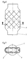
- Ein Wärmetauscherrohr mit kreuzdrallförmig eingebrachten Sicken.
- Fig. 7:
- Einen Schnitt durch ein Rohr mit drallförmig eingebrachten Sicken.
- Fig. 1:
- A heat exchanger tube with an even change in cross-section.
- Fig. 2:
- A heat exchanger tube with gradual change in cross section.
- Fig. 3:
- A section through a tube with an oval cross-section.
- Fig. 4:
- A section through a tube with a rectangular cross-section.
- Fig. 5:
- A cut through a pipe with support points for high pressure resistance.
- Fig. 6:
- A heat exchanger tube with cross-helical beads.
- Fig. 7:
- A cut through a tube with swirl-like beads.
Das Wärmetauscherrohr besitzt an seinen beiden Enden einen etwa kreisförmigen Anschlußquerschnitt 1. Der gesamte dazwischenliegende mittlere Rohrteil ist hier durch Pressen von zwei Seiten als flacher Kanal 2 ausgebildet, dessen Querschnittsform über die Länge konstant ist oder variiert. Beispielsweise erfolgt die Querschnittsänderung kontinuierlich wie in Fig. 1 oder in Stufen 3 wie in Fig. 2. Es lassen sich im wesentlichen ovale 4 sowie rechteckförmige Querschnitte 5 herstellen. An eingeprägten Abstützpunkten 6 tragen die Rohrwände hohe Druckbelastungen von außen ab. Um den Wärmeübergang zu begünstigen, sind am mittleren Rohrbereich drallförmig oder kreuzdrallförmig verlaufende Sicken 7 angebracht.The heat exchanger tube has an approximately circular
Claims (5)
dadurch gekennzeichnet, daß der zwischen den Anschlußquerschnitten (1) liegende mittlere Rohrteil durch vorzugsweise zweiseitiges Pressen umgeformt ist.Heat exchanger tube according to claim 1,
characterized in that the central tube part lying between the connection cross sections (1) is formed by preferably two-sided pressing.
dadurch gekennzeichnet, daß der mittlere Rohrteil einen im wesentlichen ovalen (4) oder rechteckförmigen (5) Querschnitt aufweist oder in einer Hochdruckausführung an einigen Punkten (6) in der Mitte des Querschnitts bis zum Berühren von zwei gegenüberliegenden Rohrwänden zusammengepreßt ist.Heat exchanger tube according to claims 1 and 2,
characterized in that the central tube part has a substantially oval (4) or rectangular (5) cross-section or is compressed in a high pressure version at some points (6) in the middle of the cross-section until two opposite tube walls come into contact.
dadurch gekennzeichnet, daß zusätzlich zum Beispiel drallförmig, kreuzdrallförmig oder radial verlaufende Prägungen oder Sicken (7) am mittleren Rohrteil aufgebracht sind.Heat exchanger tube according to claims 1 to 3,
characterized in that, in addition, for example, helical, cross-helical or radial embossments or beads (7) are applied to the central tube part.
dadurch gekennzeichnet, daß innen und/oder außen die Rauhigkeit der Rohrwand mit eingedrehten Riefen oder einer aufgebrachten Beschichtung erhöht wird.Heat exchanger tube according to claims 1 to 4,
characterized in that the roughness of the tube wall is increased with turned grooves or an applied coating on the inside and / or outside.
Applications Claiming Priority (2)
| Application Number | Priority Date | Filing Date | Title |
|---|---|---|---|
| DE29517325U | 1995-11-02 | ||
| DE29517325U DE29517325U1 (en) | 1995-11-02 | 1995-11-02 | Heat exchanger tube |
Publications (2)
| Publication Number | Publication Date |
|---|---|
| EP0772017A2 true EP0772017A2 (en) | 1997-05-07 |
| EP0772017A3 EP0772017A3 (en) | 1998-07-29 |
Family
ID=8014884
Family Applications (1)
| Application Number | Title | Priority Date | Filing Date |
|---|---|---|---|
| EP19960114202 Withdrawn EP0772017A3 (en) | 1995-11-02 | 1996-09-05 | Heat exchanger tube |
Country Status (2)
| Country | Link |
|---|---|
| EP (1) | EP0772017A3 (en) |
| DE (1) | DE29517325U1 (en) |
Cited By (5)
| Publication number | Priority date | Publication date | Assignee | Title |
|---|---|---|---|---|
| DE19725454A1 (en) * | 1997-06-16 | 1999-01-21 | Georg Wall | Sheet-pile with outside hook strips for sheet-pile walling |
| EP1221579A1 (en) | 2001-01-05 | 2002-07-10 | hde Metallwerk GmbH | Heat exchanger tube for liquid and gaseous media |
| WO2005014667A1 (en) * | 2003-07-24 | 2005-02-17 | Bayer Technology Services Gmbh | Method and device for the elimination of volatile substances from high-viscous media |
| US7575623B2 (en) | 2003-07-07 | 2009-08-18 | Bayer Technology Services Gmbh | Method for leaching aluminium-metal alloys |
| GB2509762A (en) * | 2013-01-14 | 2014-07-16 | Halla Visteon Climate Control | Tube for a heat exchanger |
Families Citing this family (6)
| Publication number | Priority date | Publication date | Assignee | Title |
|---|---|---|---|---|
| DE29709136U1 (en) * | 1997-05-24 | 1997-07-24 | Viessmann Werke Gmbh & Co, 35108 Allendorf | Heat exchanger tube |
| DE19731190A1 (en) * | 1997-07-21 | 1999-01-28 | Buderus Heiztechnik Gmbh | Heat exchanger pipe for hot gases in boiler |
| FR2793313B1 (en) * | 1999-05-04 | 2001-08-03 | Guillot Ind Sa | HEAT EXCHANGER FOR EQUIPPING A HOT WATER BOILER |
| DE102004020346B4 (en) * | 2004-04-27 | 2009-06-10 | Robert Bosch Gmbh | Condensing boiler |
| DE102009013269A1 (en) * | 2009-03-05 | 2010-09-09 | E.G.O. Elektro-Gerätebau GmbH | Flow heater and method of making a flow heater |
| ES2769277T3 (en) * | 2016-07-26 | 2020-06-25 | S A R I Stampi Articoli Ind Di Zen Bortolo | Tubular device for the transit of a heat exchange fluid, particularly for heat exchangers |
Citations (1)
| Publication number | Priority date | Publication date | Assignee | Title |
|---|---|---|---|---|
| DE7427097U (en) | 1976-06-10 | R. & G. Schmoele Metallwerke, 5750 Menden | Tube for heat exchanger for liquid media |
Family Cites Families (5)
| Publication number | Priority date | Publication date | Assignee | Title |
|---|---|---|---|---|
| US4216819A (en) * | 1976-09-09 | 1980-08-12 | Union Carbide Corporation | Enhanced condensation heat transfer device and method |
| JPS59501171A (en) * | 1982-06-29 | 1984-07-05 | アラーズ ヴェルクステッダー アーベー | tube heat exchanger |
| SE456935B (en) * | 1984-05-24 | 1988-11-14 | Armaturjonsson Ab | HEAT EXCHANGER THERE FLOWING PLATES WITH STRILHAIR ARE PLACED IN EACH SLING OF A SERPENT INFORMATION PIPE AND SUITABLE FOR PREPARATION |
| AT400365B (en) * | 1993-10-15 | 1995-12-27 | Fercher Josef | Heat exchanger |
| DE4343405A1 (en) * | 1993-12-18 | 1995-06-22 | Friedrich Ambs Gmbh & Co Kg Ap | Heat exchange tube for tube cluster heat exchanger |
-
1995
- 1995-11-02 DE DE29517325U patent/DE29517325U1/en not_active Expired - Lifetime
-
1996
- 1996-09-05 EP EP19960114202 patent/EP0772017A3/en not_active Withdrawn
Patent Citations (1)
| Publication number | Priority date | Publication date | Assignee | Title |
|---|---|---|---|---|
| DE7427097U (en) | 1976-06-10 | R. & G. Schmoele Metallwerke, 5750 Menden | Tube for heat exchanger for liquid media |
Cited By (11)
| Publication number | Priority date | Publication date | Assignee | Title |
|---|---|---|---|---|
| DE19725454A1 (en) * | 1997-06-16 | 1999-01-21 | Georg Wall | Sheet-pile with outside hook strips for sheet-pile walling |
| DE19725454C2 (en) * | 1997-06-16 | 1999-05-20 | Georg Wall | Sheet pile |
| EP1221579A1 (en) | 2001-01-05 | 2002-07-10 | hde Metallwerk GmbH | Heat exchanger tube for liquid and gaseous media |
| DE10100241A1 (en) * | 2001-01-05 | 2002-07-18 | Hde Metallwerk Gmbh | Heat exchanger tube for liquid or gaseous media |
| US7575623B2 (en) | 2003-07-07 | 2009-08-18 | Bayer Technology Services Gmbh | Method for leaching aluminium-metal alloys |
| WO2005014667A1 (en) * | 2003-07-24 | 2005-02-17 | Bayer Technology Services Gmbh | Method and device for the elimination of volatile substances from high-viscous media |
| CN100467495C (en) * | 2003-07-24 | 2009-03-11 | 拜尔技术服务有限责任公司 | Method and apparatus for removing volatile substances from highly viscous media |
| US8074371B2 (en) | 2003-07-24 | 2011-12-13 | Bayer Technology Services Gmbh | Process and apparatus for removing volatile substances from highly viscous media |
| GB2509762A (en) * | 2013-01-14 | 2014-07-16 | Halla Visteon Climate Control | Tube for a heat exchanger |
| GB2509762B (en) * | 2013-01-14 | 2015-02-04 | Halla Visteon Climate Control | Tube for Heat Exchanger |
| US10113811B2 (en) | 2013-01-14 | 2018-10-30 | Hanon Systems | Tube for heat exchanger |
Also Published As
| Publication number | Publication date |
|---|---|
| DE29517325U1 (en) | 1996-02-01 |
| EP0772017A3 (en) | 1998-07-29 |
Similar Documents
| Publication | Publication Date | Title |
|---|---|---|
| EP1178278B1 (en) | Heat exchange tube with twisted inner fins | |
| EP0845647B1 (en) | Flat tube heat exchanger with twisted tube ends | |
| DE102006017432B4 (en) | Inner heat exchanger with calibrated helical finned tube | |
| EP0772017A2 (en) | Heat exchanger tube | |
| DE19903833A1 (en) | Integrated collector heat exchanger assembly | |
| EP0990828A2 (en) | Flat pipe with multichannel arrangement | |
| EP3301378A1 (en) | Heat exchanger tube and heating boiler having such a heat exchanger tube | |
| DE102010008175B4 (en) | Heat exchanger | |
| DE102012007970A1 (en) | Heat exchanger for air conditioning system of motor vehicle, has inner tube section and outer tube section, which encloses inner tube section by forming intermediate space that is flow-throughable by heat exchange medium | |
| CH666539A5 (en) | HEAT EXCHANGER TUBE AND HEAT EXCHANGER MADE THEREOF. | |
| EP2447626B1 (en) | Heat exchanger, in particular for use with refrigerated cabinets | |
| EP1918659A2 (en) | Heat exchanger | |
| DE102008014523A1 (en) | heater | |
| DE2153654A1 (en) | Forced-through heat exchanger in lightweight construction, preferably for air conditioning units with compression refrigeration systems | |
| DE4343405A1 (en) | Heat exchange tube for tube cluster heat exchanger | |
| DE2029910A1 (en) | Pipes for heat exchangers | |
| DE102016006913A1 (en) | heat exchanger tube | |
| EP1557627A1 (en) | Flow duct | |
| EP2157382A2 (en) | Heating device | |
| DE102005058153B4 (en) | Heat exchanger with multi-channel flat tubes | |
| EP2158434A1 (en) | Rear wall condenser for domestic refrigerators and freezers | |
| EP1602886B1 (en) | Boiler | |
| DE3830800C1 (en) | Heat exchanger | |
| DE102007010958A1 (en) | Heizölvorwärmer | |
| DE102007023696B4 (en) | Condenser for household refrigerators |
Legal Events
| Date | Code | Title | Description |
|---|---|---|---|
| PUAI | Public reference made under article 153(3) epc to a published international application that has entered the european phase |
Free format text: ORIGINAL CODE: 0009012 |
|
| AK | Designated contracting states |
Kind code of ref document: A2 Designated state(s): AT CH DE FR LI NL |
|
| PUAL | Search report despatched |
Free format text: ORIGINAL CODE: 0009013 |
|
| AK | Designated contracting states |
Kind code of ref document: A3 Designated state(s): AT CH DE FR LI NL |
|
| STAA | Information on the status of an ep patent application or granted ep patent |
Free format text: STATUS: THE APPLICATION IS DEEMED TO BE WITHDRAWN |
|
| 18D | Application deemed to be withdrawn |
Effective date: 19990130 |