EP0772017A2 - Tube d'échangeur de chaleur - Google Patents
Tube d'échangeur de chaleur Download PDFInfo
- Publication number
- EP0772017A2 EP0772017A2 EP19960114202 EP96114202A EP0772017A2 EP 0772017 A2 EP0772017 A2 EP 0772017A2 EP 19960114202 EP19960114202 EP 19960114202 EP 96114202 A EP96114202 A EP 96114202A EP 0772017 A2 EP0772017 A2 EP 0772017A2
- Authority
- EP
- European Patent Office
- Prior art keywords
- cross
- heat exchanger
- tube
- section
- exchanger tube
- Prior art date
- Legal status (The legal status is an assumption and is not a legal conclusion. Google has not performed a legal analysis and makes no representation as to the accuracy of the status listed.)
- Withdrawn
Links
Images

Classifications
-
- F—MECHANICAL ENGINEERING; LIGHTING; HEATING; WEAPONS; BLASTING
- F28—HEAT EXCHANGE IN GENERAL
- F28F—DETAILS OF HEAT-EXCHANGE AND HEAT-TRANSFER APPARATUS, OF GENERAL APPLICATION
- F28F1/00—Tubular elements; Assemblies of tubular elements
- F28F1/02—Tubular elements of cross-section which is non-circular
- F28F1/06—Tubular elements of cross-section which is non-circular crimped or corrugated in cross-section
-
- F—MECHANICAL ENGINEERING; LIGHTING; HEATING; WEAPONS; BLASTING
- F24—HEATING; RANGES; VENTILATING
- F24H—FLUID HEATERS, e.g. WATER OR AIR HEATERS, HAVING HEAT-GENERATING MEANS, e.g. HEAT PUMPS, IN GENERAL
- F24H1/00—Water heaters, e.g. boilers, continuous-flow heaters or water-storage heaters
- F24H1/22—Water heaters other than continuous-flow or water-storage heaters, e.g. water heaters for central heating
- F24H1/40—Water heaters other than continuous-flow or water-storage heaters, e.g. water heaters for central heating with water tube or tubes
-
- F—MECHANICAL ENGINEERING; LIGHTING; HEATING; WEAPONS; BLASTING
- F28—HEAT EXCHANGE IN GENERAL
- F28F—DETAILS OF HEAT-EXCHANGE AND HEAT-TRANSFER APPARATUS, OF GENERAL APPLICATION
- F28F1/00—Tubular elements; Assemblies of tubular elements
- F28F1/10—Tubular elements and assemblies thereof with means for increasing heat-transfer area, e.g. with fins, with projections, with recesses
- F28F1/42—Tubular elements and assemblies thereof with means for increasing heat-transfer area, e.g. with fins, with projections, with recesses the means being both outside and inside the tubular element
- F28F1/424—Means comprising outside portions integral with inside portions
- F28F1/426—Means comprising outside portions integral with inside portions the outside portions and the inside portions forming parts of complementary shape, e.g. concave and convex
Definitions
- the invention relates to a heat exchanger tube according to the preamble of claim 1.
- tube bundle heat exchangers are also used in heating technology.
- condensing technology is becoming increasingly important, ie the boilers use the heat of condensation contained in the water vapor by cooling the combustion gases to below the dew point.
- the heat exchangers used on the one hand require a large heat transfer surface which is adapted to the lower temperature differences between exhaust gas and heating water, but on the other hand construction volumes and material expenditure are limited.
- corrosion resistance and a low pressure loss when exposed to exhaust gas and condensed water must be guaranteed, which is why stainless steel is mainly used as the material.
- the heat transfer performance depends very much on the flow conditions on the heat exchanger tubes.
- a turbulent flow inside the pipes has proven to be favorable. This can be achieved with a corresponding amount of material by means of turbulators which are inserted into the tubes or by a special design of the tube wall.
- the invention had for its object to provide a heat exchanger tube which can be produced cost-effectively and which achieves high heat transfer rates with a low use of material by targeted introduction of flow.
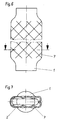
- the heat exchanger tube has an approximately circular connection cross section at its two ends.
- the entire intermediate middle tube part is formed by pressing from two sides as a flat channel, the cross-sectional shape of which varies or is constant over the length.
- the central tube part essentially has an oval and rectangular cross section. So it is possible with simple forming techniques to vary this in the longitudinal direction, by the flow rate to keep the heating gases flowing inside at the same level when they cool down.
- the flat channels prevent core flow and promote heat dissipation in the wall area. When used under high pressure loads from the outside, support points can easily be created in the center of the profile by pressing two opposite pipe walls together.
- embossments, beads or beads which run in a spiral, cross-spiral or radial fashion are preferably provided on the central tube region.
- the roughness of the inner and / or outer tube wall can be increased by screwed-in grooves or a coating.
- the measures lead to the formation of a continuous, highly turbulent boundary layer without significant core flow.
- the heat transfer properties reach qualities as in plate heat exchangers.
- the use of pipes also offers advantages in terms of strength and low-stress connection when creating larger units. Tests have confirmed lower pressure drop on the hot gas side of these pipes than with inserted turbulators. This means that very efficient, compact and material-saving heat exchangers can be manufactured, especially for the condensing technology application.
- the heat exchanger tube has an approximately circular connection cross section 1 at its two ends.
- the entire intermediate tube section here is formed by pressing from two sides as a flat channel 2, the cross-sectional shape of which is constant or varies over the length. For example, the change in cross section takes place continuously as in FIG. 1 or in stages 3 as in FIG. 2.
- oval 4 and rectangular cross sections 5 can be produced.
- the tube walls bear high pressure loads from the outside.
- beads 7 running in a swirl-like or cross-swirl shape are attached to the central tube area.
Landscapes
- Engineering & Computer Science (AREA)
- Physics & Mathematics (AREA)
- Thermal Sciences (AREA)
- Mechanical Engineering (AREA)
- General Engineering & Computer Science (AREA)
- Geometry (AREA)
- Chemical & Material Sciences (AREA)
- Combustion & Propulsion (AREA)
- Heat-Exchange Devices With Radiators And Conduit Assemblies (AREA)
Applications Claiming Priority (2)
| Application Number | Priority Date | Filing Date | Title |
|---|---|---|---|
| DE29517325U | 1995-11-02 | ||
| DE29517325U DE29517325U1 (de) | 1995-11-02 | 1995-11-02 | Wärmetauscherrohr |
Publications (2)
| Publication Number | Publication Date |
|---|---|
| EP0772017A2 true EP0772017A2 (fr) | 1997-05-07 |
| EP0772017A3 EP0772017A3 (fr) | 1998-07-29 |
Family
ID=8014884
Family Applications (1)
| Application Number | Title | Priority Date | Filing Date |
|---|---|---|---|
| EP19960114202 Withdrawn EP0772017A3 (fr) | 1995-11-02 | 1996-09-05 | Tube d'échangeur de chaleur |
Country Status (2)
| Country | Link |
|---|---|
| EP (1) | EP0772017A3 (fr) |
| DE (1) | DE29517325U1 (fr) |
Cited By (5)
| Publication number | Priority date | Publication date | Assignee | Title |
|---|---|---|---|---|
| DE19725454A1 (de) * | 1997-06-16 | 1999-01-21 | Georg Wall | Spundbohle |
| EP1221579A1 (fr) | 2001-01-05 | 2002-07-10 | hde Metallwerk GmbH | Tube d'échangeur de chaleur pour fluides liquides et gazeux |
| WO2005014667A1 (fr) * | 2003-07-24 | 2005-02-17 | Bayer Technology Services Gmbh | Procede et dispositif pour eliminer des substances volatiles contenues dans des milieux a viscosite elevee |
| US7575623B2 (en) | 2003-07-07 | 2009-08-18 | Bayer Technology Services Gmbh | Method for leaching aluminium-metal alloys |
| GB2509762A (en) * | 2013-01-14 | 2014-07-16 | Halla Visteon Climate Control | Tube for a heat exchanger |
Families Citing this family (6)
| Publication number | Priority date | Publication date | Assignee | Title |
|---|---|---|---|---|
| DE29709136U1 (de) * | 1997-05-24 | 1997-07-24 | Viessmann Werke Gmbh & Co, 35108 Allendorf | Wärmetauscherrohr |
| DE19731190A1 (de) * | 1997-07-21 | 1999-01-28 | Buderus Heiztechnik Gmbh | Wärmetauscherrohr für die Heizgasführung in Heizkesseln |
| FR2793313B1 (fr) * | 1999-05-04 | 2001-08-03 | Guillot Ind Sa | Echangeur de chaleur destine a equiper une chaudiere a eau chaude |
| DE102004020346B4 (de) * | 2004-04-27 | 2009-06-10 | Robert Bosch Gmbh | Brennwertheizkessel |
| DE102009013269A1 (de) * | 2009-03-05 | 2010-09-09 | E.G.O. Elektro-Gerätebau GmbH | Durchfluss-Heizeinrichtung und Verfahren zur Herstellung einer Durchfluss-Heizeinrichtung |
| PL3276290T3 (pl) * | 2016-07-26 | 2020-04-30 | S.A.R.I. - Stampi Articoli Industriali Di Zen Bortolo | Urządzenie rurowe dla przepływu płynu wymieniającego ciepło, w szczególności w wymiennikach ciepła |
Citations (1)
| Publication number | Priority date | Publication date | Assignee | Title |
|---|---|---|---|---|
| DE7427097U (de) | 1976-06-10 | R. & G. Schmoele Metallwerke, 5750 Menden | Rohr für Wärmeaustauscher für flüssige Medien |
Family Cites Families (5)
| Publication number | Priority date | Publication date | Assignee | Title |
|---|---|---|---|---|
| US4216819A (en) * | 1976-09-09 | 1980-08-12 | Union Carbide Corporation | Enhanced condensation heat transfer device and method |
| US4589481A (en) * | 1982-06-29 | 1986-05-20 | Ab Zander & Ingestrom | Tube heat exchanger |
| SE456935B (sv) * | 1984-05-24 | 1988-11-14 | Armaturjonsson Ab | Vaermevaexlare daer stroemningsplaatar med strilhaal aer placerade i varje slingaav ett serpentinformat roer samt saett foer framstaellning |
| AT400365B (de) * | 1993-10-15 | 1995-12-27 | Fercher Josef | Wärmetauscher |
| DE4343405A1 (de) * | 1993-12-18 | 1995-06-22 | Friedrich Ambs Gmbh & Co Kg Ap | Rohr, insbesondere zur Verwendung als Wärmetauschrohr für Rohrbündelwärmeübertrager |
-
1995
- 1995-11-02 DE DE29517325U patent/DE29517325U1/de not_active Expired - Lifetime
-
1996
- 1996-09-05 EP EP19960114202 patent/EP0772017A3/fr not_active Withdrawn
Patent Citations (1)
| Publication number | Priority date | Publication date | Assignee | Title |
|---|---|---|---|---|
| DE7427097U (de) | 1976-06-10 | R. & G. Schmoele Metallwerke, 5750 Menden | Rohr für Wärmeaustauscher für flüssige Medien |
Cited By (10)
| Publication number | Priority date | Publication date | Assignee | Title |
|---|---|---|---|---|
| DE19725454A1 (de) * | 1997-06-16 | 1999-01-21 | Georg Wall | Spundbohle |
| DE19725454C2 (de) * | 1997-06-16 | 1999-05-20 | Georg Wall | Spundbohle |
| EP1221579A1 (fr) | 2001-01-05 | 2002-07-10 | hde Metallwerk GmbH | Tube d'échangeur de chaleur pour fluides liquides et gazeux |
| DE10100241A1 (de) * | 2001-01-05 | 2002-07-18 | Hde Metallwerk Gmbh | Wärmetauscherrohr für flüssige oder gasförmige Medien |
| US7575623B2 (en) | 2003-07-07 | 2009-08-18 | Bayer Technology Services Gmbh | Method for leaching aluminium-metal alloys |
| WO2005014667A1 (fr) * | 2003-07-24 | 2005-02-17 | Bayer Technology Services Gmbh | Procede et dispositif pour eliminer des substances volatiles contenues dans des milieux a viscosite elevee |
| US8074371B2 (en) | 2003-07-24 | 2011-12-13 | Bayer Technology Services Gmbh | Process and apparatus for removing volatile substances from highly viscous media |
| GB2509762A (en) * | 2013-01-14 | 2014-07-16 | Halla Visteon Climate Control | Tube for a heat exchanger |
| GB2509762B (en) * | 2013-01-14 | 2015-02-04 | Halla Visteon Climate Control | Tube for Heat Exchanger |
| US10113811B2 (en) | 2013-01-14 | 2018-10-30 | Hanon Systems | Tube for heat exchanger |
Also Published As
| Publication number | Publication date |
|---|---|
| DE29517325U1 (de) | 1996-02-01 |
| EP0772017A3 (fr) | 1998-07-29 |
Similar Documents
| Publication | Publication Date | Title |
|---|---|---|
| DE10038624C2 (de) | Wärmeübertragungsrohr mit gedrallten Innenrippen | |
| DE102006017432B4 (de) | Innerer Wärmeübertrager mit kalibriertem wendelförmigen Rippenrohr | |
| EP0772017A2 (fr) | Tube d'échangeur de chaleur | |
| DE19903833A1 (de) | Integrierte Sammler-Wärmeübertrager-Baueinheit | |
| EP0845647B1 (fr) | Echangeur de chaleur à tubes plats avec extrémité de tubes déformée par torsion | |
| EP0990828A2 (fr) | Tuyau plat avec canaux multiples | |
| EP3040638B1 (fr) | Tuyau de transfert de chaleur et chaudiere dotee d'un tel tuyau de transfert de chaleur | |
| DE102010008175B4 (de) | Wärmeübertrager | |
| CH666539A5 (de) | Waermetauscherrohr und daraus gebildeter waermetauscher. | |
| DE2153654A1 (de) | Zwangsdurchlauf-Wärmeaustauscher in Leichtbauweise, vorzugsweise für Klimageräte mit Kompressionskälteanlagen | |
| DE4343405A1 (de) | Rohr, insbesondere zur Verwendung als Wärmetauschrohr für Rohrbündelwärmeübertrager | |
| DE2029910A1 (de) | Rohre fur Wärmeaustauscher | |
| EP2157382A2 (fr) | Appareil de chauffage | |
| WO2009115447A2 (fr) | Appareil de chauffage | |
| DE4212074C1 (en) | Electric continuous flow meter e.g. for coffee machine - has tubular heaters pressed so that walls of flow tube have recesses altering cross-section | |
| EP1557627A1 (fr) | Canal d'écoulement | |
| WO2008141626A1 (fr) | Condenseur de paroi arrière de réfrigérateurs de ménage | |
| EP1602886A2 (fr) | Chaudière | |
| DE102016006913A1 (de) | Wärmeübertragerrohr | |
| DE3830800C1 (en) | Heat exchanger | |
| DE102007010958A1 (de) | Heizölvorwärmer | |
| DE102009032121A1 (de) | Brennwertkessel | |
| DE102007023696B4 (de) | Verflüssiger für Haushaltskältegeräte | |
| DE19523047C1 (de) | Elektrischer Durchlauferhitzer für flüssige Medien | |
| DE8432762U1 (de) | Waermeaustauscher, insbesondere fuer waermepumpen und kaelteanlagen |
Legal Events
| Date | Code | Title | Description |
|---|---|---|---|
| PUAI | Public reference made under article 153(3) epc to a published international application that has entered the european phase |
Free format text: ORIGINAL CODE: 0009012 |
|
| AK | Designated contracting states |
Kind code of ref document: A2 Designated state(s): AT CH DE FR LI NL |
|
| PUAL | Search report despatched |
Free format text: ORIGINAL CODE: 0009013 |
|
| AK | Designated contracting states |
Kind code of ref document: A3 Designated state(s): AT CH DE FR LI NL |
|
| STAA | Information on the status of an ep patent application or granted ep patent |
Free format text: STATUS: THE APPLICATION IS DEEMED TO BE WITHDRAWN |
|
| 18D | Application deemed to be withdrawn |
Effective date: 19990130 |