EP0771709A1 - Displacement detector in transfer apparatus and driving controller of transfer member - Google Patents
Displacement detector in transfer apparatus and driving controller of transfer member Download PDFInfo
- Publication number
- EP0771709A1 EP0771709A1 EP96120360A EP96120360A EP0771709A1 EP 0771709 A1 EP0771709 A1 EP 0771709A1 EP 96120360 A EP96120360 A EP 96120360A EP 96120360 A EP96120360 A EP 96120360A EP 0771709 A1 EP0771709 A1 EP 0771709A1
- Authority
- EP
- European Patent Office
- Prior art keywords
- displacement
- wire rope
- pulley
- coil
- rope
- Prior art date
- Legal status (The legal status is an assumption and is not a legal conclusion. Google has not performed a legal analysis and makes no representation as to the accuracy of the status listed.)
- Granted
Links
Images






Classifications
-
- B—PERFORMING OPERATIONS; TRANSPORTING
- B61—RAILWAYS
- B61B—RAILWAY SYSTEMS; EQUIPMENT THEREFOR NOT OTHERWISE PROVIDED FOR
- B61B12/00—Component parts, details or accessories not provided for in groups B61B7/00 - B61B11/00
- B61B12/06—Safety devices or measures against cable fracture
-
- B—PERFORMING OPERATIONS; TRANSPORTING
- B61—RAILWAYS
- B61B—RAILWAY SYSTEMS; EQUIPMENT THEREFOR NOT OTHERWISE PROVIDED FOR
- B61B12/00—Component parts, details or accessories not provided for in groups B61B7/00 - B61B11/00
- B61B12/02—Suspension of the load; Guiding means, e.g. wheels; Attaching traction cables
Definitions
- This invention relates to a displacement detector of a rope against a guide member for detecting a displacement degree when the rope guided by a guide member such as a pulley is displaced from a standard point set in the guide member, and to a drive control device of a transfer member for controlling a driving speed by means of the displacement detector.
- a transfer apparatus having a rope guided by a guide member includes, for example, a lift device, car gondola device, ropeway, and cable car (hereinafter referred to as the lift device) which consist of pulleys and wire ropes, and what is generally known is a ski lift which is disposed at skiing grounds.
- the lift device because of its structure, carriers suspended from the wire rope have a drawback of being easily influence by a side wind with resect to the moving direction of the carriers.
- the ski lift is disposed among the mountains where a gust of wind blows, there is a danger that the wire rope easily comes off the pulley because of the sway of the carriers from side to side due to a side wind.
- an off-position detector is disposed on each lift device to detect the off-position of the wire rope from a pulley on one hand, and a monitor camera is used to monitor the sideward sway of the carriers on the other hand.
- the above off-position detector detects the off-position of the wire rope from a pulley when the wire rope displaced from the pulley presses a switch such as a limit switch which is disposed on the side of the pulley. And, to monitor the sideward sway of carriers with the monitor camera, monitor cameras are disposed at a plurality of places along the stretched direction of the wire rope, and a man keeps observing the sideward sway of carriers due to wind on monitors from the cameras.
- the pulley In the lift device, the pulley is generally fixed and the wire rope is designed to travel, but there is a lift device where the wire rope is conversely fixed and the pulley travels, and there is a danger in the same way as above that the pulley is easily displaced from the wire rope because of a sideward swat of the carrier due to a side wind.
- the wire rope travels.
- the aforementioned conventional off-position detector is aimed at preventing a secondary hazard which may be caused by operating the lift with the wire roped displaced from a pulley, and has a problem that it cannot prevent the off-position of the wire rope from the pulley. And, monitoring of the sideward sway of carriers through the monitor cameras can hardly prevent the wire rope from coming off of the pulley groove due to a gust of wind. Further, the recent ski lift is operated at a high speed and the number of lifts carrying a plurality of passengers are increasing, and a gondola and ropeway are enlarging in size, and accordingly the possibility of off-position of the wire rope from the pulley is increasing, leading to the increase of injured people due to accidents every year.
- this invention aims to provide a displacement detector of a metallic rope against a guide member which detects a displacement degree of a wire rope from a guide member, so that the off-position of the rope from the pulley can be prevented automatically efficiently, and which can be easily installed to existing lift facilities; and also aims to provide a drive control device of the transfer member which detects a displacement degree of a rope from a standard position in a pulley groove at a plurality of points, controls an operating speed of the transfer member according to each displacement degree to prevent the off-position of the rope from the pulley groove automatically and efficiently, improves the safety and carrying capacity of the lift substantially, and can be easily disposed on existing lift facilities.
- This invention is a detector for detecting a relative position between a rope (2) and a guide member (13) in a transfer apparatus including the rope (2) travelling by itself or fixed to a support; the guide member (13) such as a pulley engaging with the rope, and fixed to the support or travelling by itself; a transformer member travelling with the rope (2) or with the guide member (13); and a displacement detector (1) for detecting a relative position between the rope and the guide member, fitted in the proximity of the guide member (13) and keeping a gap with the guide member always constant; wherein the displacement detector (1) includes medium generation means for generating a position detection medium emitted from the detector towards the rope (2) and detection means for detecting the displacement of this medium.
- a displacement degree of the rope particularly a displacement degree from a standard position when displaced from an optional position as a standard can be detected by a simple structure, so that the off-position of the rope such as a wire rope from the guide member such as a pulley can be prevented automatically and efficiently by disposing the detector at a prescribed position.
- this invention provides a speed control means to drive the transfer member to the displacement detector, and this speed control means is a drive control device of the transfer member for controlling a speed of the transfer member according to an output signal of a displacement degree from the displacement detector.
- this speed control means is a drive control device of the transfer member for controlling a speed of the transfer member according to an output signal of a displacement degree from the displacement detector.
- a displacement degree of the rope from the standard point determined within the guide member is detected by the displacement detector, and according to the displacement degree, the operating speed of the transfer member is synthetically controlled according to the displacement degree so as to be able to prevent the rope from being displaced from the guide member automatically and efficiently, improving the safety and carrying capacity of the transfer member substantially.
- Fig. 1 is a schematic illustration of the displacement detector for the metallic rope in the guide member in a first embodiment of this invention.
- Fig. 2 is a diagram showing the output characteristics of the hall element with respect to a displacement degree.
- Fig. 3 is a circuit diagram showing the detection circuit using the hall element.
- Fig. 4 is a circuit diagram using a magnetic resistance element.
- Fig. 5 is a circuit diagram using a magnetic diode.
- Fig. 6 is a perspective view showing the displacement detector attached to the pole of a ski lift.
- Fig. 7 is a schematic illustration of the displacement detector for the metallic rope in the guide member in a second embodiment.
- Fig. 8 is a diagram showing the output characteristics of the hall element with respect to a displacement degree.
- Fig. 9 is a schematic illustration of the displacement detector for the metallic rope in the guide member in a third embodiment.
- Fig. 10 is a block diagram showing an independent detection of the displacement degree in vertical and horizontal directions.
- Fig. 11 is a schematic illustration of the displacement detector for the metallic rope in the guide member in a fourth embodiment.
- Fig. 12 is a circuit diagram showing a detection circuit using a coil.
- Fig. 13 is a schematic illustration of the displacement detector for the metallic rope in the guide member in a fifth embodiment.
- Fig. 14 is a schematic illustration of the displacement detector for the metallic rope in the guide member in a sixth embodiment.
- Fig. 15 is a view showing the detection unit corresponding to a lay of the wire rope according to a seventh embodiment.
- Fig. 16 is a circuit diagram showing the detection circuit for detecting a displacement degree by removing a ripple component.
- Fig. 17 is a circuit diagram showing the detection circuit using the magnetoelectric conversion element according to an eighth embodiment and not requiring the offset cancel circuit.
- Fig. 18 is a circuit diagram of the displacement detector according to a ninth embodiment.
- Fig. 19 is circuit diagram of the displacement detector according to a tenth embodiment.
- Fig. 20 is a sectional view showing the displacement detector according to an eleventh embodiment.
- Fig. 21 is a side view showing the above displacement detector.
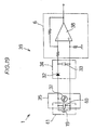
- Fig. 22 is a circuit diagram showing the above displacement detector.
- Fig. 23 is a sectional view showing the displacement detector according to a twelfth embodiment.
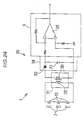
- Fig. 24 is a circuit diagram of the above displacement detector.
- Fig. 25 is a view showing the detection unit corresponding to a lay of the wire rope according to a seventh embodiment.
- Fig. 26 is a schematic illustration of the displacement detector showing the fourteenth embodiment.
- Fig. 27 is a block diagram showing the above displacement detector.
- Fig. 28 is a block diagram showing a fifteenth embodiment.
- Fig. 29 is a block diagram showing a sixteenth embodiment.
- Fig. 30 is a schematic illustration showing a seventeenth embodiment.
- Fig. 31 is a front view showing the displacement detector attached to the pole of a ski lift.
- Fig. 32 is a block diagram of the lift drive controlling device according to this invention.
- Fig. 33 is a view showing the control of a motor speed with respect to the displacement degree.
- Fig. 34 is a schematic illustration showing the entire lift drive controlling device.
- Fig. 35 is a block diagram of the lift drive controlling device of another embodiment.
- Fig. 36 is a schematic illustration showing the entire of the above lift drive controlling device.
- Fig. 37 is a circuit diagram showing the detection circuit to obtain velocity information using a ripple component.
- Fig. 38 is a view showing an output characteristic with respect to the displacement degree of the hall element.
- the displacement detector of a rope in a first embodiment to a fifteenth embodiment detects a displacement degree of a wire rope with respect to a guide member according to an output voltage from a magnetoelectric conversion means which is disposed in a magnetic circuit formed by a magnet and a wire rope wherein the magnet is disposed to face the wire rope which is made of a magnetic substance to form the rope.
- magnetism is used as a medium for detecting a position emitted from the detector toward the rope.
- a displacement detector 1 of a first embodiment consists of a pulley 13 which is a guide member for guiding a wire rope 2, a magnet 3 which is kept at a certain distance from the pulley 13 and disposed with its either magnetic pole opposed to the wire rope 2, magnetic flux B which is generated from N pole of the magnet 3 and passes through the wire rope 2, a hall element 4 which is a magnetoelectric conversion element disposed on the magnetic flux B, and a detection circuit 5 shown in Fig. 3 for detecting an output voltage from the hall element 4 as shown in Fig. 1.
- the above magnet 3 is a permanent magnet, and has a prescribed volume according to detection accuracy or range of a displacement degree, or a prescribed volume and energy product.
- N pole is opposed to the wire rope 2
- S pole may be opposed to the wire rope 2.
- a displacement degree of the wire rope 2 is obtained by detecting a change of magnetic flux quantity in the magnetic circuit 9 by the hall element 4 to be described afterward.
- the above hall element 4 is disposed on the magnetic circuit 9 immediately above the magnetic pole (N pole) on the side of the wire rope 2 from the magnet 3 as shown in Fig. 1 and detects a variation of magnetic flux B in the magnetic circuit 9.
- This hall element 4 is one which is called as a magnetoelectric conversion element and obtains a prescribed voltage in proportion to a change of magnetic flux quantity applied to the element;
- Fig. 2 shows output characteristics in this embodiment.
- the displacement degree in the figure indicates a sideward displacement when the wire rope 2 is moved in a horizontal direction (indicated by the arrows) from a standard of displacement which is determined when the wire rope 2 is positioned immediately above the above magnetic pole, and an output (voltage) from the hall element 4 in proportion to the sideward displacement is obtained as an absolute value.
- the broken line in Fig. 2 indicates an output due to a static magnetic field already applied to the hall element 4, and is adjusted to an output characteristic indicated by the solid line by an offset cancel part 7 of the detection circuit 5 to be described afterward.
- the plus direction of the displacement degree is for example in the right direction with respect to the standard position
- the minus direction is in the left direction with respect to the standard position.
- magnetic flux B passing through the wire rope 2 which is a magnetic substance is formed by the magnetic circuit 9, and with the magnetic flux quantity to be applied to the hall element 4 when the wire rope 2 is on the standard position as the standard of a displacement degree, the increased or decreased quantity is obtained from the magnetic flux quantity which is applied to the hall element 4 by magnetic flux B which is deflected by being attracted toward the wire rope 2, to detect a displacement degree of the wire rope 2 from the standard position.
- the above detection circuit 5 is to amplify the output voltage from the hall element 4 and to remove the output by the static magnetic field produced by the permanent magnet when displacement of the wire rope 2 does not occur.
- This detection circuit 5 comprises a differential amplifying part 6, an offset cancel part 7, and an inversion amplifying part 8 as shown in Fig. 3.
- the above differential amplifying part 6 is a common differential amplifying circuit comprising an operation amplifier 10 whose plus and minus terminal on the input side are connected with two output lines from the above hall element 4, and amplifies a deviation of the output voltage which is outputted from the hall element 4 toward between both output lines.
- noise is remedied by receiving the input by differential amplification.
- the voltage applied to the hall element 4 is to flow a prescribed input electricity to drive the hall element 4.
- the output voltages with the polarity of the differential amplifying part 6 inverted from the output side is outputted.
- the above offset cancel part 7 is to remove the output by the above static magnetic field and comprises an operation amplifier 11 wherein an offset adjusting resistor is connected to the minus terminal on the input side, and the plus terminal is directly connected to the output side. And, DC voltage (offset cancel voltage) of straight polarity equivalent to the output by the static magnetic field is outputted from the output side of the operation amplifier 11.
- offset cancel voltage offset cancel voltage
- the above inversion amplifying part 8 further amplifies the output voltage which is determined to be a net segment based on the variation of magnetic flux B by the above offset cancel voltage, and also invert the polarity to the positive electrode.
- it is an inversion amplifying circuit by a common operation amplifier 12.
- the resistor in Fig. 3 is for setting a amplification factor.
- the hall element was used, but the magnetic resistor element shown in Fig. 4 or a magnetic diode shown in Fig. 5 may be used. And, in Fig. 4 and Fig. 5, description of the offset cancel circuit has been omitted.
- Fig. 6 the above displacement detector 1 which is used for a ski lift device 15 will be described.
- the transfer member of this invention may be described as a lift, and the transfer apparatus may be described as a lift device.
- the ski lift device 15 is constituted by building a plurality of posts on a slope at a skiing ground, rotatably supporting a plurality of pulleys 13 at the upper part of the posts, stretching the wire rope 2 from which carriers are suspended through the rotation (or revolving) groove of each pulleys, and driving the wire rope in the stretched direction to move the carriers.
- the above displacement detector 1 is configured by accommodating the hall element 4, magnet 3, and detection circuit 5 from the top in a detection unit 16 as shown in Fig, 4, and this detection unit 16 is attached to the upper part of the pole 14 by means of fixing plates 17 along the peripheral groove direction of the pulley 13.
- the detection unit 16 is attached below the wire rope 2, on the side of the wire rope 2 opposite from the side where the lift is travelling, or above the wire rope 2.
- the detection unit 16 is disposed at a position excepting a portion where the lift member passes.
- the detection unit 16 is attached between the pulleys or positioned outside of the pulleys.
- a plate 17 is disposed to and projected from each bearing plate 13b which supports bearings 13a of the pulleys 13, and the detection unit 16 is attached between the plates 17.
- the detection unit 16 is disposed outside of the pulley 13.
- the standard position of displacement of the displacement detector 1 shall be aligned with the bottom center position of the pulley peripheral groove.
- a displacement degree to be generated when the wire rope 2 stretched to the pulley groove is displaced from the standard position in the groove can be always detected, and the off-position of the wire rope from the pulley groove can be prevented automatically and efficiently.
- the hall element 4 is used, an abrupt displacement of the wire rope 2 by a gust of wind or a change gradually caused over a long time can be detected at high sensitivity.
- the standard position of displacement is optional.
- displacement detector 1 In the displacement detector 1 according to a second embodiment shown in Fig. 7, two magnets 3, 3 are disposed on both ends of yoke 18 with a certain interval therebetween with different magnetic poles faced against the wire rope 2 to comprise the magnetic circuit 9 which forms magnetic flux B being generated from N pole of one magnet 3, passed across the wire rope 2 or through the yoke 18, and returned to S pole of the other magnet 3.
- the magnetic circuit 9 which forms magnetic flux B being generated from N pole of one magnet 3, passed across the wire rope 2 or through the yoke 18, and returned to S pole of the other magnet 3.
- the direction of displacement of the wire rope 2 was not clear because the output from the hall element was an absolute value, but in this embodiment, the direction of displacement with respect to the horizontal direction can be specified because the output characteristics shown in Fig. 8 are obtained.
- the detection circuit is the same as in the first embodiment.
- two magnets 3, 3 are disposed with a certain interval therebetween to comprise the magnetic circuit 9 which forms magnetic flux B being generated from N pole of one magnet 3, passed across the wire rope 2 or through the yoke 18, and returned to S pole of the other magnet 3, and two hall elements 4, 4 are disposed at certain positions on the magnetic circuit 9.
- this embodiment can specify the displacement direction in the vertical direction separately from the horizontal direction.
- the magnetic flux quantities to be detected by both hall elements 4, 4 are increased or decreased in the same way, and from the sum obtained by adding the magnetic flux quantities detected by both hall elements 4, 4, it can be specified that the wire rope 2 has been displaced in the vertical direction. In this case, even if one magnetic flux quantity is deducted from the other magnetic flux quantity, the magnetic flux quantity is constant, and the displaced direction cannot be obtained.
- the displacement detector 1 obtains the displacement degree of magnetic flux B from an induced electromotive force generated in a coil due to a change of magnetic flux B interlinking with the coil, while the first to third embodiment obtain the displacement degree of magnetic flux B from a magnetic flux quantity detected by the hall element.
- the displacement detector 1 of this embodiment comprises the magnet 3 disposed with either magnetic pole faced toward the wire rope 2, a coil 19 disposed on magnetic flux B which is generated from N pole of the magnet 3 and passed across the wire rope 2, and the detection circuit 5 for detecting the output voltage from the coil 19, as shown in Fig. 11.
- the above coil 19 is disposed on the magnetic circuit 9 immediately above the magnetic pole (N pole) of the magnet 3 on the side of the wire rope 2, and the above magnetic flux B is interlinked with the coil 19 as shown in Fig. 11. Therefore, it is determined as a standard of displacement when the wire rope 2 is positioned immediately on the above magnetic pole, and magnetic flux B interlinked with the coil 19 in the standard of displacement is determined as a standard of displacement degree, then a variation of magnetic flux B is obtained from an induced electromotive force generated in the coil 19 when the wire rope 2 is displaced in a side way (indicated by arrows) with respect to the direction of the above magnetic flux B, to detect a displacement degree of the wire rope 2.
- the above detection circuit 5 is to amplify the output voltage from the above coil 19.
- This detection circuit 5 is a common differential amplifying circuit comprising an operation amplifier 10 having both ends of the above coil 19 connected to plus and minus terminals on the input side as shown in Fig. 12, and amplifies a deviation between both ends of the coil 19 due to the induced electromotive force generated in the coil 19.
- the voltage applied to both ends of the coil 19 is to drive the circuit. Since a change in magnetic flux B is obtained from the induced electromotive force generated in the coil 19, a displacement of the wire rope 2 can be detected, and so the offset cancel part is not required. And, since the coil is used, a sharp displacement of the wire rope 2 due to a gust of wind can be detected at high sensitivity.
- displacement detector 1 In the displacement detector 1 according to a fifth embodiment shown in Fig. 13, in the same way as the above second embodiment, as compared with the case using a single magnet 3, displacement detecting sensitivity is improved and magnet quantity is decreased, and a displacement direction with respect to the horizontal direction can be specified.
- the detection circuit 5 is the same as in the fourth embodiment.
- a displacement direction with respect to the vertical direction can be specified separately from the horizontal direction in the same way as in the above third embodiment. But, the offset cancel voltage of Fig. 10 is not required.
- a seventh embodiment shown in Fig. 15 is a detector using a strand such as the wire rope 2 as the metallic rope.
- the wire rope 2 is broadly used for the rope of the ski lift device. Since the wire rope 2 has a lay, detection in the direction of one diameter of the wire rope 2 may be erroneous because of a ripple component contained in the output voltage due to the lay. In other words, even when the wire rope 2 is running with a certain distance kept from the hall element 4, the wire rope 2 is detected as being periodically approached to or separated from the hall element because of the presence of the lay.
- the magnet 3 and two sets of hall elements 4 are disposed in parallel with an interval of 1/2 of pitch P of the lay along the axial direction of the wire rope 2 as shown in Fig. 15, and the output voltage from each hall element is synthesized, so that the ripple component can be removed from the output voltage.
- the detection circuit 5 of this embodiment is structured by connecting the differential amplifying parts 6, 6 connected to the two sets of hall elements 4 and the offset cancel part 7 to the input terminal on the minus side of the inversion amplifying part 8 as shown in Fig. 16.
- the hall element used in this embodiment may be a coil.
- the displacement detector 1 according to an eighth embodiment shown in Fig. 17 has the offset cancel part 7 removed from the detection circuit 5 using the magnetoelectric conversion element in the above first through third embodiments, and connects a capacitor 33 between the differential amplifying part 6 and the inversion amplifying part 8.
- a displacement only of the wire rope 2 can be detected in the same way as in the fourth through sixth embodiment.
- a displacement degree of the metallic rope, or a displacement degree when the metallic rope is displaced from an optional position which is a standard can be detected, so that the off-position of the wire rope from the pulley's groove can be prevented automatically and efficiently by disposing the detector at a certain position, and this detector can be easily disposed on an existing lift facilities.
- the displacement detector 1 according to a ninth embodiment shown in Fig. 18 comprises the coil 19 and a detection circuit 39.
- the above detection circuit 39 comprises a detection part 35 for detecting an impedance change generated in the coil 19, a rectifying part 34 for rectifying an AC signal into a DC signal, and a differential amplifying part 6 for amplifying the DC signal.
- the above detection part 35 comprises a voltage dividing resister 36 connected in parallel to the coil 19. and an oscillator 37 connected to one end of the voltage dividing resistor 36 as shown in Fig. 18.
- the above coil 19 has a high-frequency signal applied by the oscillator 37, and when the wire rope 2 is displaced from the standard position and approaches to the coil 19, the inductance of the coil 19 changes, resulting in an impedance change. Accordingly, a voltage dividing ratio of the coil and the voltage dividing resistor 36 changes, and a voltage dividing voltage applied to both ends of the coil is changed.
- the above rectifying part 34 is a common smoothing circuit consisting of a diode 32 and a capacitor 33, and a voltage dividing voltage signal generated in the above detecting part 35 is rectified into a DC voltage signal.
- the above differential amplifying part 6 is a common differential amplifying circuit which comprises an operation amplifier whose plus and minus terminals on the input side are connected with two output lines from the above rectifying part 34, and a deviation of the DC voltage signal outputted between both output lines is amplified to a certain level and obtained as a displacement degree.
- the displacement detector 1 according to a tenth embodiment shown in Fig. 19 comprises a coil 19 and a detection circuit 39.
- the above detection circuit 39 comprises a detection part 35, a rectifying part 34 for rectifying an AC signal into a DC signal, and a differential amplifying part 6 for amplifying the DC signal.
- the above detecting part 35 constitutes a resonance circuit 41 by having a capacitor 40 connected in parallel to the above coil 19 as shown in Fig. 19, and constitutes an oscillation circuit by having the oscillator 37 connected in parallel to the resonance circuit 41 (oscillation source) and having the resonance circuit 41 resonated by the oscillator 37.
- This oscillation circuit is set by the coil 19 and the capacitor 40 so that a certain oscillation characteristic is obtained.
- the leakage flux generated from the coil 19 passes across the wire rope 2.
- an eddy current loss is generated within the wire rope 2, and the coil's impedance is changed by this loss. Therefore, a value of quality factor Q of the oscillation circuit is varied. degrading the characteristic as the oscillation circuit.
- the oscillation output which is changed in the above detection part 35 by a displacement of the wire rope is rectified into a DC voltage signal by the smoothing circuit consisting of the diode 32 and the capacitor 33.
- the above differential amplifying part 6 is a common differential amplifying circuit which comprises an operation amplifier whose plus and minus terminals on the input side are connected with two output lines from the above rectifying part 34, and a deviation of the DC voltage signal outputted between both output lines is amplified to a certain level and obtained as a displacement degree.
- the displacement detector 1 according to an eleventh embodiment shown in Fig. 20 and Fig. 21 comprises a pulley 13, displacement detecting coils 19, a revolving part 27, a revolving side coil 28, a stationary part 29, a stationary side coil 30, a detecting part 35, a rectifying part 34, and a differential amplifying part 6.
- the above displacement detecting coils 19 are disposed at an equal interval in the peripheral direction on one side of the pulley 13 as shown in Fig. 21, and each displacement detecting coil is connected to the detecting part 35 via a rotary transformer 31 which consists of the stationary side coil 30 and the revolving side coil 28, to be described afterward, mutually connected in series on the circuit as shown in Fig. 22. In this embodiment, they are disposed at three points at an equal interval in the peripheral direction, but may be disposed in more numbers.
- the above revolving part 27 is a small projected part formed coaxially with the pulley 13 on one side of the pulley 13, and the above revolving side coil 28 is wound in certain turns on the outer periphery of the revolving part 27.
- the above stationary part 29 is formed in the shape of a cylinder which has a larger diameter than the revolving 27 and whose one end is closed, and the above stationary side coil 30 is wound in certain turns on the inner periphery of the stationary part 29.
- the above detecting part 35 comprises the oscillator 37 which is connect in parallel to the above stationary side coil 30 as shown in Fig. 22.
- the above stationary side coil 30 has a high-frequency signal applied by the oscillator 37, and when the wire rope 2 is displaced from the standard position of displacement to approach to the displacement detecting coil 19, mutual induction is caused between the wire rope 2 and each displacement detecting coil 19, causing an impedance change in each displacement detecting coil 19.
- a voltage which is applied between both ends of the displacement detecting coil 19 at this time is applied with its voltage changed to both ends of the above stationary side coil 30 via the above rotary transformer 31.
- the above rectifying part 34 is connected to both ends of the stationary side coil 30, and a voltage signal which is applied between both ends of the stationary side coil 30 is rectified into a DC voltage signal by the smoothing circuit consisting of the diode 32 and the capacitor 33.
- the above differential amplifying part 6 is a common differential amplifying circuit which comprises an operation amplifier 38 whose plus and minus terminals on the input side are connected with two output lines from the above rectifying part 34, and a deviation of the DC voltage signal outputted between both output lines is amplified to a certain level and obtained as a displacement degree.
- the AC signal by the oscillator 37 is applied to the displacement detecting coil 19 via the rotary transformer 31 consisting of the stationary side coil 30 and the revolving side coil 28, falling in a state supplied.
- the impedance of the displacement detecting coil 19 is changed.
- a voltage applied to both ends of the displacement detecting coil 19 is changed, the changed voltage is rectified into a DC voltage in the rectifying part 34 via the rotary transformer 31, and then amplified to a certain level in the differential amplifying part 6 to obtain a displacement degree.
- the application of the AC signal to the displacement detecting coil 19 and the detecting of the impedance change of the displacement detecting coil 19 can be made without contacting to the pulley 13.
- the displacement detector 1 of a twelfth embodiment shown in Fig. 23 comprises displacement detecting coils 19, magnets 3, a revolving part 27, a revolving side coil 28, a stationary part 29, a stationary side coil 30, a rectifying part 34, and a differential amplifying part 6.
- the above displacement detecting coils 19 are disposed at an equal interval in the peripheral direction on one side of the pulley 13, and each displacement detecting coil 19 is connected in series as shown in Fig. 23. As shown in Fig. 24, both ends of the displacement detecting coil 19 connected in series are connected to the rectifying part 34 via the rotary transformer 31 consisting of the revolving side coil 28 and the stationary side coil 30 to be described afterward. In this embodiment, they are disposed at three points at an equal interval in the peripheral direction.
- the above magnets 3 are disposed apart from the displacement detecting coil 19 on the back of the above displacement detecting coil 19 far from the pulley's groove as shown in Fig. 23. These magnets 3 are to form magnetic flux B which is generated from N pole and passes across the wire rope 2.
- the above revolving part 27 is a small projected part formed coaxially with the pulley 13 on one side of the pulley 13, and the above revolving side coil 28 is wound in certain turns on the outer periphery of the revolving part 27.
- the above stationary part 29 is formed in the shape of a cylinder which has a larger diameter than the revolving 27 and whose one end is closed, and the above stationary side coil 30 is wound in certain turns on the inner periphery of the stationary part 29.
- the above rectifying part 34 is connected to both ends of the stationary side coil 30 as shown in Fig. 24, and a voltage signal due to an induced electromotive force generated in the above revolving side coil 28 is rectified into a DC voltage signal by the smoothing circuit consisting of the diode 32 and the capacitor 33.
- the above differential amplifying part 6 is a common differential amplifying circuit which comprises an operation amplifier 38 whose plus and minus terminals on the input side are connected with two output lines from the above rectifying part 34 as shown in Fig. 24, and a deviation of the DC voltage signal outputted between both output lines is amplified to a certain level and obtained as a displacement degree.
- the displacement detector 1 is a detector using a strand such as the wire rope 2 as the metallic rope in the same way as in the seventh embodiment.
- two sets of coils 19 and the magnet 3 are disposed in parallel with an interval of 1/2 of pitch P of the lay along the axial direction of the wire rope 2 as shown in Fig. 25, and the output voltage from each coil 19 is synthesized, so that the ripple component can be removed from the output voltage.
- the output voltage having a phase inverted by 180 degrees from each coil 19 is obtained, and by adding each output voltage, the ripple component can be removed, so that without being influenced by the lay of the wire rope 2, a displacement degree can be detected at high accuracy.
- the rope is a wire rope 2 made of a magnetic substance
- a magnet 3 is disposed to oppose the wire rope 2
- a coil 19 is disposed on a magnetic circuit 9 formed by the magnet 3 and the wire rope 2
- a core 19a made of a powerful magnetic substance is inserted in the coil
- a fixed resistor 36 is connected in series to the coil 19
- a constant-frequency signal from the oscillator 37 is applied to the coil 19
- a DC voltage of both ends of the coil is detected, to detect a displacement degree of the wire rope from the pulley.
- This embodiment is based on the knowledge that the impedance of the coil 19 changes in proportion to the permeability of the core 19a of a powerful magnetic substance.
- the permeability of the core 19a of a powerful magnetic substance changes when the saturated state of the core 19a of a powerful magnetic substance changes by a change in magnetic flux of the magnetic circuit 9.
- the magnetic flux of the magnetic circuit 9 changes when a distance between the wire rope 2 and the coil 19 changes. Therefore, a displacement of the wire rope 2 is represented by an impedance change of the coil 19, so that a displacement of the wire rope 2 can be detected by detecting an impedance change of the coil 19.
- an AC signal is applied to detect an impedance change of the coil 19, to detect (DC voltage) a voltage dividing segment with the fixed resistor 36, and to maintain this detection reliability, it is necessary to keep the core 19a of a powerful magnetic substance in a saturated state on one hand, and to make a magnetomotive force N.I (ampere turn) by a current flown in the coil 19 well smaller than a DC magnetic field on the other hand.
- a power amplifying part is disposed between the oscillator 37 and the fixed resistor 36, and since a DC segment of the low-frequency signal detected in the detection circuit generates an offset, it is adjusted by the offset cancel part 7.
- a fifteenth embodiment shown in Fig. 28 applies a DC voltage to the coil 19 without using the magnet 3 which is a permanent magnet to effect the same operation as the magnet 3.
- the same operation as above is effected but, since the permanent magnet is not used, the number of parts is decreased, and by adjusting a DC voltage as desired, the generated magnetic force (performance of the magnet generated by applying a DC voltage) can be changed, a detection sensitivity can be easily changed, and as a result, it can be easily applies to various wire ropes.
- N.I ampere turn
- a displacement degree when the metallic rope is displaced from the standard position within the groove can be detected by an impedance change generated in the coil, so that the construction of the detector is simple, and the off-position of the wire rope from the pulley's groove can be prevented automatically and efficiently. Furthermore, it can be easily mounted on existing lift facilities. And, by constructing the transformer by the revolving side coil and the stationary side coil (ninth and thirteenth embodiments).
- a sixteenth embodiment shown in Fig. 29 uses an ultrasonic wave for a displacement detecting medium which is emitted toward the rope 2, the ultrasonic wave sent to the rope by an ultrasonic wave device 51 for sending is reflected from the rope, the reflected ultrasonic wave is received by an ultrasonic wave device 52 for receiving the wave, the sent wave signal is multiplied by the received wave signal obtained a delay time t later, and a displacement degree of a positional change of the rope with respect to the pulley is detected by measuring the frequency.
- a frequency modulation and continuous wave method FM-CW method
- a continuous wave (transmitted wave) whose frequency is modulated by a modulation signal generator and a voltage control oscillator is used to transmit a wave from the ultrasonic wave device 51 to the rope 2.
- a received wave obtained a delay time t later is multiplied with a transmitted wave signal to take out a low frequency component alone by a low pass filter so as to obtain an output change according to a displacement.
- a displacement degree of the rope from the pulley can be detected.
- a seventeenth embodiment shown in Fig. 30 uses light as a medium for detecting a position which is emitted toward the rope 2, the light emitted from a floodlight element 53 toward the rope is reflected from the rope 2, the reflected light is received by a light receiving element 54, and by a change of the output signal from this light receiving element 54, a displacement degree of the rope 2 from the pulley is detected.
- light emitted from the floodlight element (for example, a light emitting diode) is finely reduced through a floodlight lens 55 and irradiated to the rope 2.
- the light reflected from the rope 2 is converged on a light receiving lens 56, and forms an image on the light receiving element (for example, a phototransistor array).
- the position and intensity of irradiation on the light receiving element are changed because an image-formed position varies according to a displacement of the rope, and according to the change of the output signal of the light receiving element, a displacement degree of the rope from the pulley is detected.
- the displacement detector is positioned outside of the pulley 13 as the detection unit 16, and as shown in Fig. 31, when the four pulleys 13 are arranged for example, the detector may be may be disposed between the outer and inner pulleys.
- a drive control device for a transfer member such as a lift in this embodiment comprises using the displacement detector illustrated in the first embodiment through the eighth embodiment, and as shown in Fig. 32, consists of the displacement detecting means 1 for detecting a displacement degree of the wire rope from the pulley's groove, and a speed control means 25 for controlling a drive speed of the wire rope according to the output signal from the displacement detecting means 1. Now, the speed control means 25 will be described.
- the above speed control means 25 comprises a motor speed control circuit 21, a driving circuit 22, a motor 24, and a speed detector 23 as shown in Fig. 32.
- the above motor speed control circuit 21 controls the motor speed as shown in Fig. 33 according to the output signal from the above displacement detecting means 1. As shown in the figure, when a displacement degree exceeds a certain level, the motor 24 is braked, while when a displacement degree is small, the motor 24 is operated at a high speed constantly without being varied. Thus, the safety and carrying capacity of the lift can be improved sharply.
- the above driving circuit 22 starts or brakes the motor 24, or increases or decreases its speed according to the control signal from the above motor speed control circuit 21.
- the above speed detector 23 detect the present speed from the motor 24 and feeds back the detected result to the above motor speed control circuit 21, and the motor speed control circuit 21 compares and judges if the revolving speed of the motor 24 is made under a prescribed control from that signal, and outputs the control signal to the above driving circuit 22, if necessary.
- the safety and carrying capacity of the lift can be synthetically improved by taking the output signal due to the detection of a displacement degree from a plurality of pulleys as a logical sum into the above motor speed control circuit 21 as shown in Fig. 34.
- the standard position of displacement is optional.
- the lift drive control device to be described below comprises using the displacement detector shown in the ninth embodiment to thirteenth embodiment, and the lift device of this embodiment, as shown in Fig. 35, comprises a coil 19, the displacement detecting means 1 for detecting a displacement degree of the wire rope 2 from the pulley's groove, and a speed control means 25 for controlling a driving speed of the wire rope 2 according to the output signal from the displacement detecting means 1.
- This speed control means 25 is basically the same with conventional ones.
- the speed of the motor 24 is controlled according to a displacement degree detected when the wire rope 2 stretched through the pulley is displaced from the standard position within the pulley's groove, the off-position of the wire rope 2 from the pulley's groove can be prevented automatically and efficiently.
- the safety and carrying capacity of the lift can be synthetically improved by taking the output signal due to the detection of a displacement degree from a plurality of pulleys as a logical sum into the above motor speed control circuit 21.
- the speed of the wire used for the lift drive control device is also detected by the detection circuit shown in Fig. 37.
- This detection circuit uses a compensation circuit for the ripple component shown in Fig. 16, and by taking out either of the hall element outputs in this compensation circuit, or by detecting the ripple component, information on a speed is obtained.
- the detecting coil 19 is mounted on the pulley 13 shown in Fig. 20 and Fig. 21, the output of each detection coil generates a signal in the shape of burst every time the detection coil approaches to the wire by the revolution of the pulley, so that it is possible to use the signal in the shape of burst as a speed signal.
- a displacement degree of the wire rope from the standard point determined in each pulley's groove by the displacement detecting means disposed at several points, and a travelling speed of the lift is synthetically controlled according to each displacement degree, so that the off-position of the wire rope from the pulley's groove can be prevented automatically and efficiently, and the safety and carrying capacity of the lift can be improved sharply.
- the drive control device for the transfer member such as a lift according to this invention, the detection of an abnormality in case of the off-position of the aforementioned rope such as a wire from the guide member such as a pulley can be prevented from taking place, and in an ordinary daily inspection, a displacement of the wire from the pulley or wear of a rubber disposed on the pulley can be checked without going to see it, besides such a check can be made in higher reliability than before.
- the aforementioned invention is particularly suitable for ski lifts. Further, in addition to the ski lifts, it can be used for luggage carrying lifts, gondolas, ropeways, etc. as long as a metallic or non-metallic rope is guided by a guide member. And, it can also be used to detect, for example, a breakage, deformation or damage of a rope other than the detection of a displacement degree of a rope with respect to a guide member.
Landscapes
- Engineering & Computer Science (AREA)
- Transportation (AREA)
- Mechanical Engineering (AREA)
- Measurement Of Length, Angles, Or The Like Using Electric Or Magnetic Means (AREA)
- Control And Safety Of Cranes (AREA)
- Control Of Position Or Direction (AREA)
Abstract
Description
- This invention relates to a displacement detector of a rope against a guide member for detecting a displacement degree when the rope guided by a guide member such as a pulley is displaced from a standard point set in the guide member, and to a drive control device of a transfer member for controlling a driving speed by means of the displacement detector.
- Heretofore, a transfer apparatus having a rope guided by a guide member includes, for example, a lift device, car gondola device, ropeway, and cable car (hereinafter referred to as the lift device) which consist of pulleys and wire ropes, and what is generally known is a ski lift which is disposed at skiing grounds. In such a ski lift, because of its structure, carriers suspended from the wire rope have a drawback of being easily influence by a side wind with resect to the moving direction of the carriers. In addition, since the ski lift is disposed among the mountains where a gust of wind blows, there is a danger that the wire rope easily comes off the pulley because of the sway of the carriers from side to side due to a side wind. For a safety precaution, an off-position detector is disposed on each lift device to detect the off-position of the wire rope from a pulley on one hand, and a monitor camera is used to monitor the sideward sway of the carriers on the other hand.
- The above off-position detector detects the off-position of the wire rope from a pulley when the wire rope displaced from the pulley presses a switch such as a limit switch which is disposed on the side of the pulley. And, to monitor the sideward sway of carriers with the monitor camera, monitor cameras are disposed at a plurality of places along the stretched direction of the wire rope, and a man keeps observing the sideward sway of carriers due to wind on monitors from the cameras.
- In the lift device, the pulley is generally fixed and the wire rope is designed to travel, but there is a lift device where the wire rope is conversely fixed and the pulley travels, and there is a danger in the same way as above that the pulley is easily displaced from the wire rope because of a sideward swat of the carrier due to a side wind. Now, description will be made with reference to an example where the wire rope travels.
- Incidentally, the aforementioned conventional off-position detector is aimed at preventing a secondary hazard which may be caused by operating the lift with the wire roped displaced from a pulley, and has a problem that it cannot prevent the off-position of the wire rope from the pulley. And, monitoring of the sideward sway of carriers through the monitor cameras can hardly prevent the wire rope from coming off of the pulley groove due to a gust of wind. Further, the recent ski lift is operated at a high speed and the number of lifts carrying a plurality of passengers are increasing, and a gondola and ropeway are enlarging in size, and accordingly the possibility of off-position of the wire rope from the pulley is increasing, leading to the increase of injured people due to accidents every year. In addition, to monitor the sideward sway of carriers through the conventional monitor cameras, it is not efficient because a man has to keep watching, and there is a defect that a standard for judging the presence or not of danger as to the degree of sideward sway of carriers is vague, Furthermore, to dispose the above plurality of monitor cameras to many existing lift facilities, construction work is made on a large scale, and so there is a disadvantage that the cost of construction becomes high.
- In view of the above, this invention aims to provide a displacement detector of a metallic rope against a guide member which detects a displacement degree of a wire rope from a guide member, so that the off-position of the rope from the pulley can be prevented automatically efficiently, and which can be easily installed to existing lift facilities; and also aims to provide a drive control device of the transfer member which detects a displacement degree of a rope from a standard position in a pulley groove at a plurality of points, controls an operating speed of the transfer member according to each displacement degree to prevent the off-position of the rope from the pulley groove automatically and efficiently, improves the safety and carrying capacity of the lift substantially, and can be easily disposed on existing lift facilities.
- This invention is a detector for detecting a relative position between a rope (2) and a guide member (13) in a transfer apparatus including the rope (2) travelling by itself or fixed to a support; the guide member (13) such as a pulley engaging with the rope, and fixed to the support or travelling by itself; a transformer member travelling with the rope (2) or with the guide member (13); and a displacement detector (1) for detecting a relative position between the rope and the guide member, fitted in the proximity of the guide member (13) and keeping a gap with the guide member always constant; wherein the displacement detector (1) includes medium generation means for generating a position detection medium emitted from the detector towards the rope (2) and detection means for detecting the displacement of this medium. According to this invention, a displacement degree of the rope, particularly a displacement degree from a standard position when displaced from an optional position as a standard can be detected by a simple structure, so that the off-position of the rope such as a wire rope from the guide member such as a pulley can be prevented automatically and efficiently by disposing the detector at a prescribed position.
- And, this invention provides a speed control means to drive the transfer member to the displacement detector, and this speed control means is a drive control device of the transfer member for controlling a speed of the transfer member according to an output signal of a displacement degree from the displacement detector. According to the device of this invention, a displacement degree of the rope from the standard point determined within the guide member is detected by the displacement detector, and according to the displacement degree, the operating speed of the transfer member is synthetically controlled according to the displacement degree so as to be able to prevent the rope from being displaced from the guide member automatically and efficiently, improving the safety and carrying capacity of the transfer member substantially.
- Fig. 1 is a schematic illustration of the displacement detector for the metallic rope in the guide member in a first embodiment of this invention.
- Fig. 2 is a diagram showing the output characteristics of the hall element with respect to a displacement degree.
- Fig. 3 is a circuit diagram showing the detection circuit using the hall element.
- Fig. 4 is a circuit diagram using a magnetic resistance element.
- Fig. 5 is a circuit diagram using a magnetic diode.
- Fig. 6 is a perspective view showing the displacement detector attached to the pole of a ski lift.
- Fig. 7 is a schematic illustration of the displacement detector for the metallic rope in the guide member in a second embodiment.
- Fig. 8 is a diagram showing the output characteristics of the hall element with respect to a displacement degree.
- Fig. 9 is a schematic illustration of the displacement detector for the metallic rope in the guide member in a third embodiment.
- Fig. 10 is a block diagram showing an independent detection of the displacement degree in vertical and horizontal directions.
- Fig. 11 is a schematic illustration of the displacement detector for the metallic rope in the guide member in a fourth embodiment.
- Fig. 12 is a circuit diagram showing a detection circuit using a coil.
- Fig. 13 is a schematic illustration of the displacement detector for the metallic rope in the guide member in a fifth embodiment.
- Fig. 14 is a schematic illustration of the displacement detector for the metallic rope in the guide member in a sixth embodiment.
- Fig. 15 is a view showing the detection unit corresponding to a lay of the wire rope according to a seventh embodiment.
- Fig. 16 is a circuit diagram showing the detection circuit for detecting a displacement degree by removing a ripple component.
- Fig. 17 is a circuit diagram showing the detection circuit using the magnetoelectric conversion element according to an eighth embodiment and not requiring the offset cancel circuit.
- Fig. 18 is a circuit diagram of the displacement detector according to a ninth embodiment.
- Fig. 19 is circuit diagram of the displacement detector according to a tenth embodiment.
- Fig. 20 is a sectional view showing the displacement detector according to an eleventh embodiment.
- Fig. 21 is a side view showing the above displacement detector.
- Fig. 22 is a circuit diagram showing the above displacement detector.
- Fig. 23 is a sectional view showing the displacement detector according to a twelfth embodiment.
- Fig. 24 is a circuit diagram of the above displacement detector.
- Fig. 25 is a view showing the detection unit corresponding to a lay of the wire rope according to a seventh embodiment.
- Fig. 26 is a schematic illustration of the displacement detector showing the fourteenth embodiment.
- Fig. 27 is a block diagram showing the above displacement detector.
- Fig. 28 is a block diagram showing a fifteenth embodiment.
- Fig. 29 is a block diagram showing a sixteenth embodiment.
- Fig. 30 is a schematic illustration showing a seventeenth embodiment.
- Fig. 31 is a front view showing the displacement detector attached to the pole of a ski lift.
- Fig. 32 is a block diagram of the lift drive controlling device according to this invention.
- Fig. 33 is a view showing the control of a motor speed with respect to the displacement degree.
- Fig. 34 is a schematic illustration showing the entire lift drive controlling device.
- Fig. 35 is a block diagram of the lift drive controlling device of another embodiment.
- Fig. 36 is a schematic illustration showing the entire of the above lift drive controlling device.
- Fig. 37 is a circuit diagram showing the detection circuit to obtain velocity information using a ripple component.
- Fig. 38 is a view showing an output characteristic with respect to the displacement degree of the hall element.
- The displacement detector of a rope in a first embodiment to a fifteenth embodiment detects a displacement degree of a wire rope with respect to a guide member according to an output voltage from a magnetoelectric conversion means which is disposed in a magnetic circuit formed by a magnet and a wire rope wherein the magnet is disposed to face the wire rope which is made of a magnetic substance to form the rope. In other words, magnetism is used as a medium for detecting a position emitted from the detector toward the rope.
- A
displacement detector 1 of a first embodiment consists of apulley 13 which is a guide member for guiding awire rope 2, amagnet 3 which is kept at a certain distance from thepulley 13 and disposed with its either magnetic pole opposed to thewire rope 2, magnetic flux B which is generated from N pole of themagnet 3 and passes through thewire rope 2, ahall element 4 which is a magnetoelectric conversion element disposed on the magnetic flux B, and adetection circuit 5 shown in Fig. 3 for detecting an output voltage from thehall element 4 as shown in Fig. 1. - The
above magnet 3 is a permanent magnet, and has a prescribed volume according to detection accuracy or range of a displacement degree, or a prescribed volume and energy product. In Fig. 1, N pole is opposed to thewire rope 2, but S pole may be opposed to thewire rope 2. - A
magnetic circuit 9 which forms magnetic flux B which is emitted from N pole of themagnet 3, passes across thewire rope 2 and returns to S pole is formed by thewire rope 2 and themagnet 3. In this invention, a displacement degree of thewire rope 2 is obtained by detecting a change of magnetic flux quantity in themagnetic circuit 9 by thehall element 4 to be described afterward. - The
above hall element 4 is disposed on themagnetic circuit 9 immediately above the magnetic pole (N pole) on the side of thewire rope 2 from themagnet 3 as shown in Fig. 1 and detects a variation of magnetic flux B in themagnetic circuit 9. Thishall element 4 is one which is called as a magnetoelectric conversion element and obtains a prescribed voltage in proportion to a change of magnetic flux quantity applied to the element; Fig. 2 shows output characteristics in this embodiment. The displacement degree in the figure indicates a sideward displacement when thewire rope 2 is moved in a horizontal direction (indicated by the arrows) from a standard of displacement which is determined when thewire rope 2 is positioned immediately above the above magnetic pole, and an output (voltage) from thehall element 4 in proportion to the sideward displacement is obtained as an absolute value. The broken line in Fig. 2 indicates an output due to a static magnetic field already applied to thehall element 4, and is adjusted to an output characteristic indicated by the solid line by an offset cancelpart 7 of thedetection circuit 5 to be described afterward. In Fig. 2, when the plus direction of the displacement degree is for example in the right direction with respect to the standard position, the minus direction is in the left direction with respect to the standard position. - Therefore, magnetic flux B passing through the
wire rope 2 which is a magnetic substance is formed by themagnetic circuit 9, and with the magnetic flux quantity to be applied to thehall element 4 when thewire rope 2 is on the standard position as the standard of a displacement degree, the increased or decreased quantity is obtained from the magnetic flux quantity which is applied to thehall element 4 by magnetic flux B which is deflected by being attracted toward thewire rope 2, to detect a displacement degree of thewire rope 2 from the standard position. - The
above detection circuit 5 is to amplify the output voltage from thehall element 4 and to remove the output by the static magnetic field produced by the permanent magnet when displacement of thewire rope 2 does not occur. Thisdetection circuit 5 comprises adifferential amplifying part 6, an offset cancelpart 7, and aninversion amplifying part 8 as shown in Fig. 3. - The above
differential amplifying part 6 is a common differential amplifying circuit comprising anoperation amplifier 10 whose plus and minus terminal on the input side are connected with two output lines from theabove hall element 4, and amplifies a deviation of the output voltage which is outputted from thehall element 4 toward between both output lines. Thus, noise is remedied by receiving the input by differential amplification. The voltage applied to thehall element 4 is to flow a prescribed input electricity to drive thehall element 4. In this embodiment, the output voltages with the polarity of the differential amplifyingpart 6 inverted from the output side is outputted. - The above offset cancel
part 7 is to remove the output by the above static magnetic field and comprises anoperation amplifier 11 wherein an offset adjusting resistor is connected to the minus terminal on the input side, and the plus terminal is directly connected to the output side. And, DC voltage (offset cancel voltage) of straight polarity equivalent to the output by the static magnetic field is outputted from the output side of theoperation amplifier 11. Thus, the output voltage having the output by the static magnetic field deducted from the output voltage of reversed polarity outputted from the differential amplifyingpart 6 is obtained. - The above
inversion amplifying part 8 further amplifies the output voltage which is determined to be a net segment based on the variation of magnetic flux B by the above offset cancel voltage, and also invert the polarity to the positive electrode. Thus, it is an inversion amplifying circuit by acommon operation amplifier 12. The resistor in Fig. 3 is for setting a amplification factor. - In the above embodiment, the hall element was used, but the magnetic resistor element shown in Fig. 4 or a magnetic diode shown in Fig. 5 may be used. And, in Fig. 4 and Fig. 5, description of the offset cancel circuit has been omitted.
- In Fig. 6, the
above displacement detector 1 which is used for aski lift device 15 will be described. In the following description, the transfer member of this invention may be described as a lift, and the transfer apparatus may be described as a lift device. - The
ski lift device 15 is constituted by building a plurality of posts on a slope at a skiing ground, rotatably supporting a plurality ofpulleys 13 at the upper part of the posts, stretching thewire rope 2 from which carriers are suspended through the rotation (or revolving) groove of each pulleys, and driving the wire rope in the stretched direction to move the carriers. - The
above displacement detector 1 is configured by accommodating thehall element 4,magnet 3, anddetection circuit 5 from the top in adetection unit 16 as shown in Fig, 4, and thisdetection unit 16 is attached to the upper part of thepole 14 by means of fixingplates 17 along the peripheral groove direction of thepulley 13. Thedetection unit 16 is attached below thewire rope 2, on the side of thewire rope 2 opposite from the side where the lift is travelling, or above thewire rope 2. In other words, since a member in the vertical direction of the lift is designed to pass one side (opposite from the post) of the pulley, thedetection unit 16 is disposed at a position excepting a portion where the lift member passes. - Since a plurality of
pulleys 13 are on thepost 14, thedetection unit 16 is attached between the pulleys or positioned outside of the pulleys. In the embodiment of Fig. 6, aplate 17 is disposed to and projected from each bearingplate 13b which supportsbearings 13a of thepulleys 13, and thedetection unit 16 is attached between theplates 17. In this embodiment, thedetection unit 16 is disposed outside of thepulley 13. - When the
detection unit 16 is attached, the standard position of displacement of thedisplacement detector 1 shall be aligned with the bottom center position of the pulley peripheral groove. Thus, a displacement degree to be generated when thewire rope 2 stretched to the pulley groove is displaced from the standard position in the groove can be always detected, and the off-position of the wire rope from the pulley groove can be prevented automatically and efficiently. Since thehall element 4 is used, an abrupt displacement of thewire rope 2 by a gust of wind or a change gradually caused over a long time can be detected at high sensitivity. The standard position of displacement is optional. - Other embodiments will be described one after another with reference to the drawings. In the
displacement detector 1 according to a second embodiment shown in Fig. 7, twomagnets yoke 18 with a certain interval therebetween with different magnetic poles faced against thewire rope 2 to comprise themagnetic circuit 9 which forms magnetic flux B being generated from N pole of onemagnet 3, passed across thewire rope 2 or through theyoke 18, and returned to S pole of theother magnet 3. In this case, as compared with the case using asingle magnet 3, displacement detecting sensitivity is improved and magnet quantity is decreased. In the first embodiment, the direction of displacement of thewire rope 2 was not clear because the output from the hall element was an absolute value, but in this embodiment, the direction of displacement with respect to the horizontal direction can be specified because the output characteristics shown in Fig. 8 are obtained. The detection circuit is the same as in the first embodiment. - In the
displacement detector 1 according to a third embodiment shown in Fig. 9, twomagnets magnetic circuit 9 which forms magnetic flux B being generated from N pole of onemagnet 3, passed across thewire rope 2 or through theyoke 18, and returned to S pole of theother magnet 3, and twohall elements magnetic circuit 9. As compared with the second embodiment wherein the displacement direction can be specified in the horizontal direction only, this embodiment can specify the displacement direction in the vertical direction separately from the horizontal direction. To distinguish the vertical and horizontal displacement directions, when the magnetic flux quantity to be detected by the hall element is regarded as the magnitude of magnetic flux quantity by removing the polarity in view of magnetism, a displacement of thewire rope 2 in the horizontal direction increases the magnetic flux quantity which is detected by either hall element and decreases the magnetic flux quantity which is detected by the other hall element. From a difference obtained by deducting the reduced magnetic flux quantity from the increased magnetic flux quantity, it can be specified that thewire rope 2 has been displaced in the horizontal direction. In this case, even if the increased magnetic flux quantity is added to the decreased magnetic flux quantity, the magnetic flux quantity is constant, and the displaced direction cannot be obtained. And, when thewire rope 2 is displaced in the vertical direction, the magnetic flux quantities to be detected by bothhall elements hall elements wire rope 2 has been displaced in the vertical direction. In this case, even if one magnetic flux quantity is deducted from the other magnetic flux quantity, the magnetic flux quantity is constant, and the displaced direction cannot be obtained. - As a specific means to detect the displacement in the vertical and horizontal directions, as shown in Fig. 10, an offset cancel voltage is deducted from each output voltage which is outputted from the two
hall elements wave rectification circuit 20 to get an absolute value of a mere magnetic flux quantity without polarity in view of magnetism, one absolute value is deducted from the other absolute value to obtain the displacement direction and displacement degree in the horizontal direction, and one absolute value is added to the other absolute value to obtain the displacement direction and displacement degree in the vertical direction. Thus, it is possible to identify if the displacement of the wire rope from the groove is a displacement in the vertical direction due to a bound or a displacement in the horizontal direction due to a wind. - The
displacement detector 1 according to a fourth embodiment shown in Fig. 11 obtains the displacement degree of magnetic flux B from an induced electromotive force generated in a coil due to a change of magnetic flux B interlinking with the coil, while the first to third embodiment obtain the displacement degree of magnetic flux B from a magnetic flux quantity detected by the hall element. Thedisplacement detector 1 of this embodiment comprises themagnet 3 disposed with either magnetic pole faced toward thewire rope 2, acoil 19 disposed on magnetic flux B which is generated from N pole of themagnet 3 and passed across thewire rope 2, and thedetection circuit 5 for detecting the output voltage from thecoil 19, as shown in Fig. 11. - The
above coil 19 is disposed on themagnetic circuit 9 immediately above the magnetic pole (N pole) of themagnet 3 on the side of thewire rope 2, and the above magnetic flux B is interlinked with thecoil 19 as shown in Fig. 11. Therefore, it is determined as a standard of displacement when thewire rope 2 is positioned immediately on the above magnetic pole, and magnetic flux B interlinked with thecoil 19 in the standard of displacement is determined as a standard of displacement degree, then a variation of magnetic flux B is obtained from an induced electromotive force generated in thecoil 19 when thewire rope 2 is displaced in a side way (indicated by arrows) with respect to the direction of the above magnetic flux B, to detect a displacement degree of thewire rope 2. - The
above detection circuit 5 is to amplify the output voltage from theabove coil 19. Thisdetection circuit 5 is a common differential amplifying circuit comprising anoperation amplifier 10 having both ends of theabove coil 19 connected to plus and minus terminals on the input side as shown in Fig. 12, and amplifies a deviation between both ends of thecoil 19 due to the induced electromotive force generated in thecoil 19. The voltage applied to both ends of thecoil 19 is to drive the circuit. Since a change in magnetic flux B is obtained from the induced electromotive force generated in thecoil 19, a displacement of thewire rope 2 can be detected, and so the offset cancel part is not required. And, since the coil is used, a sharp displacement of thewire rope 2 due to a gust of wind can be detected at high sensitivity. - In the
displacement detector 1 according to a fifth embodiment shown in Fig. 13, in the same way as the above second embodiment, as compared with the case using asingle magnet 3, displacement detecting sensitivity is improved and magnet quantity is decreased, and a displacement direction with respect to the horizontal direction can be specified. Thedetection circuit 5 is the same as in the fourth embodiment. - In the
displacement detector 1 according to a sixth embodiment shown in Fig. 14, a displacement direction with respect to the vertical direction can be specified separately from the horizontal direction in the same way as in the above third embodiment. But, the offset cancel voltage of Fig. 10 is not required. - A seventh embodiment shown in Fig. 15 is a detector using a strand such as the
wire rope 2 as the metallic rope. Generally, thewire rope 2 is broadly used for the rope of the ski lift device. Since thewire rope 2 has a lay, detection in the direction of one diameter of thewire rope 2 may be erroneous because of a ripple component contained in the output voltage due to the lay. In other words, even when thewire rope 2 is running with a certain distance kept from thehall element 4, thewire rope 2 is detected as being periodically approached to or separated from the hall element because of the presence of the lay. To prevent this erroneous detection, themagnet 3 and two sets ofhall elements 4 are disposed in parallel with an interval of 1/2 of pitch P of the lay along the axial direction of thewire rope 2 as shown in Fig. 15, and the output voltage from each hall element is synthesized, so that the ripple component can be removed from the output voltage. Thedetection circuit 5 of this embodiment is structured by connecting thedifferential amplifying parts hall elements 4 and the offset cancelpart 7 to the input terminal on the minus side of theinversion amplifying part 8 as shown in Fig. 16. As described above, since the two sets ofhall elements 4 are disposed in parallel with an interval of 1/2 of pitch P of the lay along the axial direction of thewire rope 2, the output voltage having a phase inverted by 180 degrees from eachhall element 4 is obtained, and by adding each output voltage, the ripple component is removed. Therefore, without being influenced by the lay of thewire rope 2, a displacement degree can be detected at high accuracy. And, the hall element used in this embodiment may be a coil. - The
displacement detector 1 according to an eighth embodiment shown in Fig. 17 has the offset cancelpart 7 removed from thedetection circuit 5 using the magnetoelectric conversion element in the above first through third embodiments, and connects acapacitor 33 between the differential amplifyingpart 6 and theinversion amplifying part 8. Thus, a displacement only of thewire rope 2 can be detected in the same way as in the fourth through sixth embodiment. - According to the first embodiment to the eighth embodiment described above, by a simple structure comprising the magnet, metallic rope, guide member and magnetoelectric conversion element, a displacement degree of the metallic rope, or a displacement degree when the metallic rope is displaced from an optional position which is a standard can be detected, so that the off-position of the wire rope from the pulley's groove can be prevented automatically and efficiently by disposing the detector at a certain position, and this detector can be easily disposed on an existing lift facilities.
- The
displacement detector 1 according to a ninth embodiment shown in Fig. 18 comprises thecoil 19 and adetection circuit 39. - The
above detection circuit 39 comprises adetection part 35 for detecting an impedance change generated in thecoil 19, a rectifyingpart 34 for rectifying an AC signal into a DC signal, and adifferential amplifying part 6 for amplifying the DC signal. - The
above detection part 35 comprises avoltage dividing resister 36 connected in parallel to thecoil 19. and anoscillator 37 connected to one end of thevoltage dividing resistor 36 as shown in Fig. 18. Theabove coil 19 has a high-frequency signal applied by theoscillator 37, and when thewire rope 2 is displaced from the standard position and approaches to thecoil 19, the inductance of thecoil 19 changes, resulting in an impedance change. Accordingly, a voltage dividing ratio of the coil and thevoltage dividing resistor 36 changes, and a voltage dividing voltage applied to both ends of the coil is changed. - The above rectifying
part 34 is a common smoothing circuit consisting of adiode 32 and acapacitor 33, and a voltage dividing voltage signal generated in the above detectingpart 35 is rectified into a DC voltage signal. - The above
differential amplifying part 6 is a common differential amplifying circuit which comprises an operation amplifier whose plus and minus terminals on the input side are connected with two output lines from the above rectifyingpart 34, and a deviation of the DC voltage signal outputted between both output lines is amplified to a certain level and obtained as a displacement degree. - The
displacement detector 1 according to a tenth embodiment shown in Fig. 19 comprises acoil 19 and adetection circuit 39. - The
above detection circuit 39 comprises adetection part 35, a rectifyingpart 34 for rectifying an AC signal into a DC signal, and adifferential amplifying part 6 for amplifying the DC signal. - The above detecting
part 35 constitutes aresonance circuit 41 by having acapacitor 40 connected in parallel to theabove coil 19 as shown in Fig. 19, and constitutes an oscillation circuit by having theoscillator 37 connected in parallel to the resonance circuit 41 (oscillation source) and having theresonance circuit 41 resonated by theoscillator 37. This oscillation circuit is set by thecoil 19 and thecapacitor 40 so that a certain oscillation characteristic is obtained. And, when thewire rope 2 displaced from the standard position is approached to thecoil 19, the leakage flux generated from thecoil 19 passes across thewire rope 2. At this time, an eddy current loss is generated within thewire rope 2, and the coil's impedance is changed by this loss. Therefore, a value of quality factor Q of the oscillation circuit is varied. degrading the characteristic as the oscillation circuit. - With the above rectifying
part 34, the oscillation output which is changed in theabove detection part 35 by a displacement of the wire rope is rectified into a DC voltage signal by the smoothing circuit consisting of thediode 32 and thecapacitor 33. - The above
differential amplifying part 6 is a common differential amplifying circuit which comprises an operation amplifier whose plus and minus terminals on the input side are connected with two output lines from the above rectifyingpart 34, and a deviation of the DC voltage signal outputted between both output lines is amplified to a certain level and obtained as a displacement degree. - The
displacement detector 1 according to an eleventh embodiment shown in Fig. 20 and Fig. 21 comprises apulley 13,displacement detecting coils 19, a revolvingpart 27, a revolvingside coil 28, astationary part 29, astationary side coil 30, a detectingpart 35, a rectifyingpart 34, and adifferential amplifying part 6. - The above
displacement detecting coils 19 are disposed at an equal interval in the peripheral direction on one side of thepulley 13 as shown in Fig. 21, and each displacement detecting coil is connected to the detectingpart 35 via arotary transformer 31 which consists of thestationary side coil 30 and the revolvingside coil 28, to be described afterward, mutually connected in series on the circuit as shown in Fig. 22. In this embodiment, they are disposed at three points at an equal interval in the peripheral direction, but may be disposed in more numbers. - The above revolving
part 27 is a small projected part formed coaxially with thepulley 13 on one side of thepulley 13, and the above revolvingside coil 28 is wound in certain turns on the outer periphery of the revolvingpart 27. - The above
stationary part 29 is formed in the shape of a cylinder which has a larger diameter than the revolving 27 and whose one end is closed, and the abovestationary side coil 30 is wound in certain turns on the inner periphery of thestationary part 29. - The above detecting
part 35 comprises theoscillator 37 which is connect in parallel to the abovestationary side coil 30 as shown in Fig. 22. The abovestationary side coil 30 has a high-frequency signal applied by theoscillator 37, and when thewire rope 2 is displaced from the standard position of displacement to approach to thedisplacement detecting coil 19, mutual induction is caused between thewire rope 2 and eachdisplacement detecting coil 19, causing an impedance change in eachdisplacement detecting coil 19. A voltage which is applied between both ends of thedisplacement detecting coil 19 at this time is applied with its voltage changed to both ends of the abovestationary side coil 30 via the aboverotary transformer 31. - The above rectifying
part 34 is connected to both ends of thestationary side coil 30, and a voltage signal which is applied between both ends of thestationary side coil 30 is rectified into a DC voltage signal by the smoothing circuit consisting of thediode 32 and thecapacitor 33. - The above
differential amplifying part 6 is a common differential amplifying circuit which comprises anoperation amplifier 38 whose plus and minus terminals on the input side are connected with two output lines from the above rectifyingpart 34, and a deviation of the DC voltage signal outputted between both output lines is amplified to a certain level and obtained as a displacement degree. - Therefore, the AC signal by the
oscillator 37 is applied to thedisplacement detecting coil 19 via therotary transformer 31 consisting of thestationary side coil 30 and the revolvingside coil 28, falling in a state supplied. And, whenwire rope 2 is displaced from the standard point in the groove of thepulley 13 and approached to thedisplacement detecting coil 19, the impedance of thedisplacement detecting coil 19 is changed. Thus, a voltage applied to both ends of thedisplacement detecting coil 19 is changed, the changed voltage is rectified into a DC voltage in the rectifyingpart 34 via therotary transformer 31, and then amplified to a certain level in the differential amplifyingpart 6 to obtain a displacement degree. In other words, the application of the AC signal to thedisplacement detecting coil 19 and the detecting of the impedance change of thedisplacement detecting coil 19 can be made without contacting to thepulley 13. - The
displacement detector 1 of a twelfth embodiment shown in Fig. 23 comprisesdisplacement detecting coils 19,magnets 3, a revolvingpart 27, a revolvingside coil 28, astationary part 29, astationary side coil 30, a rectifyingpart 34, and adifferential amplifying part 6. - The above
displacement detecting coils 19 are disposed at an equal interval in the peripheral direction on one side of thepulley 13, and eachdisplacement detecting coil 19 is connected in series as shown in Fig. 23. As shown in Fig. 24, both ends of thedisplacement detecting coil 19 connected in series are connected to the rectifyingpart 34 via therotary transformer 31 consisting of the revolvingside coil 28 and thestationary side coil 30 to be described afterward. In this embodiment, they are disposed at three points at an equal interval in the peripheral direction. - The
above magnets 3 are disposed apart from thedisplacement detecting coil 19 on the back of the abovedisplacement detecting coil 19 far from the pulley's groove as shown in Fig. 23. Thesemagnets 3 are to form magnetic flux B which is generated from N pole and passes across thewire rope 2. - The above revolving
part 27 is a small projected part formed coaxially with thepulley 13 on one side of thepulley 13, and the above revolvingside coil 28 is wound in certain turns on the outer periphery of the revolvingpart 27. - The above
stationary part 29 is formed in the shape of a cylinder which has a larger diameter than the revolving 27 and whose one end is closed, and the abovestationary side coil 30 is wound in certain turns on the inner periphery of thestationary part 29. - The above rectifying
part 34 is connected to both ends of thestationary side coil 30 as shown in Fig. 24, and a voltage signal due to an induced electromotive force generated in the above revolvingside coil 28 is rectified into a DC voltage signal by the smoothing circuit consisting of thediode 32 and thecapacitor 33. - The above
differential amplifying part 6 is a common differential amplifying circuit which comprises anoperation amplifier 38 whose plus and minus terminals on the input side are connected with two output lines from the above rectifyingpart 34 as shown in Fig. 24, and a deviation of the DC voltage signal outputted between both output lines is amplified to a certain level and obtained as a displacement degree. - Therefore, when wire rope is displaced from the standard point in the groove of the pulley and approached to the displacement detecting coil, magnetic flux B interlinking with the coil is changed, causing an induced electromotive force in the coil. Thus, a voltage applied to both ends of the
displacement detecting coil 19 is changed, the changed voltage is rectified into a DC voltage in the rectifying part via the rotary transformer again, and then amplified to a certain level in the differential amplifying part to obtain a displacement degree. In other words, the detecting of the induced electromotive force generated in thedisplacement detecting coil 19 can be made without contacting to thepulley 13. - The
displacement detector 1 according to a thirteenth embodiment shown in Fig. 25 is a detector using a strand such as thewire rope 2 as the metallic rope in the same way as in the seventh embodiment. In this embodiment, two sets ofcoils 19 and themagnet 3 are disposed in parallel with an interval of 1/2 of pitch P of the lay along the axial direction of thewire rope 2 as shown in Fig. 25, and the output voltage from eachcoil 19 is synthesized, so that the ripple component can be removed from the output voltage. In other words, the output voltage having a phase inverted by 180 degrees from eachcoil 19 is obtained, and by adding each output voltage, the ripple component can be removed, so that without being influenced by the lay of thewire rope 2, a displacement degree can be detected at high accuracy. - In a fourteenth embodiment shown in Fig. 26 and Fig. 27, the rope is a
wire rope 2 made of a magnetic substance, amagnet 3 is disposed to oppose thewire rope 2, acoil 19 is disposed on amagnetic circuit 9 formed by themagnet 3 and thewire rope 2, acore 19a made of a powerful magnetic substance is inserted in the coil, a fixedresistor 36 is connected in series to thecoil 19, a constant-frequency signal from theoscillator 37 is applied to thecoil 19, and a DC voltage of both ends of the coil is detected, to detect a displacement degree of the wire rope from the pulley. - This embodiment is based on the knowledge that the impedance of the
coil 19 changes in proportion to the permeability of the core 19a of a powerful magnetic substance. The permeability of the core 19a of a powerful magnetic substance changes when the saturated state of the core 19a of a powerful magnetic substance changes by a change in magnetic flux of themagnetic circuit 9. And, the magnetic flux of themagnetic circuit 9 changes when a distance between thewire rope 2 and thecoil 19 changes. Therefore, a displacement of thewire rope 2 is represented by an impedance change of thecoil 19, so that a displacement of thewire rope 2 can be detected by detecting an impedance change of thecoil 19. - Specifically, as shown in Fig. 27, an AC signal is applied to detect an impedance change of the
coil 19, to detect (DC voltage) a voltage dividing segment with the fixedresistor 36, and to maintain this detection reliability, it is necessary to keep the core 19a of a powerful magnetic substance in a saturated state on one hand, and to make a magnetomotive force N.I (ampere turn) by a current flown in thecoil 19 well smaller than a DC magnetic field on the other hand. A power amplifying part is disposed between theoscillator 37 and the fixedresistor 36, and since a DC segment of the low-frequency signal detected in the detection circuit generates an offset, it is adjusted by the offset cancelpart 7. - A fifteenth embodiment shown in Fig. 28 applies a DC voltage to the
coil 19 without using themagnet 3 which is a permanent magnet to effect the same operation as themagnet 3. In this embodiment, the same operation as above is effected but, since the permanent magnet is not used, the number of parts is decreased, and by adjusting a DC voltage as desired, the generated magnetic force (performance of the magnet generated by applying a DC voltage) can be changed, a detection sensitivity can be easily changed, and as a result, it can be easily applies to various wire ropes. Furthermore, in this embodiment, since magnetic field is generated in the coil by applying a DC voltage, it is necessary to make the magnetomotive force N.I (ampere turn) due to an electric current flown in thecoil 19 same to or greater than the DC magnetic field. - In the ninth to fifteenth embodiments described above, a displacement degree when the metallic rope is displaced from the standard position within the groove can be detected by an impedance change generated in the coil, so that the construction of the detector is simple, and the off-position of the wire rope from the pulley's groove can be prevented automatically and efficiently. Furthermore, it can be easily mounted on existing lift facilities. And, by constructing the transformer by the revolving side coil and the stationary side coil (ninth and thirteenth embodiments). feeding to the detecting coil disposed on the revolving side and incorporation of a voltage signal can be made without contacting to the pulley, so that a displacement degree can be detected stably at high accuracy without being influenced by the looseness of the pulley axially supported in the process of detecting the displacement degree.
- A sixteenth embodiment shown in Fig. 29 uses an ultrasonic wave for a displacement detecting medium which is emitted toward the
rope 2, the ultrasonic wave sent to the rope by anultrasonic wave device 51 for sending is reflected from the rope, the reflected ultrasonic wave is received by anultrasonic wave device 52 for receiving the wave, the sent wave signal is multiplied by the received wave signal obtained a delay time t later, and a displacement degree of a positional change of the rope with respect to the pulley is detected by measuring the frequency. In this embodiment, a frequency modulation and continuous wave method (FM-CW method) has been employed. - More specifically, a continuous wave (transmitted wave) whose frequency is modulated by a modulation signal generator and a voltage control oscillator is used to transmit a wave from the
ultrasonic wave device 51 to therope 2. And, by reflecting from the rope, a received wave obtained a delay time t later is multiplied with a transmitted wave signal to take out a low frequency component alone by a low pass filter so as to obtain an output change according to a displacement. Thus, a displacement degree of the rope from the pulley can be detected. - A seventeenth embodiment shown in Fig. 30 uses light as a medium for detecting a position which is emitted toward the
rope 2, the light emitted from afloodlight element 53 toward the rope is reflected from therope 2, the reflected light is received by alight receiving element 54, and by a change of the output signal from thislight receiving element 54, a displacement degree of therope 2 from the pulley is detected. - Specifically, light emitted from the floodlight element (for example, a light emitting diode) is finely reduced through a
floodlight lens 55 and irradiated to therope 2. The light reflected from therope 2 is converged on alight receiving lens 56, and forms an image on the light receiving element (for example, a phototransistor array). And, the position and intensity of irradiation on the light receiving element are changed because an image-formed position varies according to a displacement of the rope, and according to the change of the output signal of the light receiving element, a displacement degree of the rope from the pulley is detected. - According to the sixteenth and seventeenth embodiments described above, since a displacement degree of the rope from the standard position within the groove can be detected based on a change of a medium other than magnetism, even if the rope is not metallic, the off-position of the rope from the pulley's groove can be prevented automatically and efficiently, and the installment to existing lift facilities is easy.
- As shown in Fig. 6, the displacement detector is positioned outside of the
pulley 13 as thedetection unit 16, and as shown in Fig. 31, when the fourpulleys 13 are arranged for example, the detector may be may be disposed between the outer and inner pulleys. - Now, a lift drive control device for controlling a speed by using the above displacement detector will be described.
- A drive control device for a transfer member such as a lift in this embodiment comprises using the displacement detector illustrated in the first embodiment through the eighth embodiment, and as shown in Fig. 32, consists of the
displacement detecting means 1 for detecting a displacement degree of the wire rope from the pulley's groove, and a speed control means 25 for controlling a drive speed of the wire rope according to the output signal from thedisplacement detecting means 1. Now, the speed control means 25 will be described. - The above speed control means 25 comprises a motor
speed control circuit 21, a drivingcircuit 22, amotor 24, and aspeed detector 23 as shown in Fig. 32. - The above motor
speed control circuit 21 controls the motor speed as shown in Fig. 33 according to the output signal from the abovedisplacement detecting means 1. As shown in the figure, when a displacement degree exceeds a certain level, themotor 24 is braked, while when a displacement degree is small, themotor 24 is operated at a high speed constantly without being varied. Thus, the safety and carrying capacity of the lift can be improved sharply. - The
above driving circuit 22 starts or brakes themotor 24, or increases or decreases its speed according to the control signal from the above motorspeed control circuit 21. - The
above speed detector 23 detect the present speed from themotor 24 and feeds back the detected result to the above motorspeed control circuit 21, and the motorspeed control circuit 21 compares and judges if the revolving speed of themotor 24 is made under a prescribed control from that signal, and outputs the control signal to theabove driving circuit 22, if necessary. - In the lift device constructed as described above, the safety and carrying capacity of the lift can be synthetically improved by taking the output signal due to the detection of a displacement degree from a plurality of pulleys as a logical sum into the above motor
speed control circuit 21 as shown in Fig. 34. The standard position of displacement is optional. - The lift drive control device to be described below comprises using the displacement detector shown in the ninth embodiment to thirteenth embodiment, and the lift device of this embodiment, as shown in Fig. 35, comprises a
coil 19, thedisplacement detecting means 1 for detecting a displacement degree of thewire rope 2 from the pulley's groove, and a speed control means 25 for controlling a driving speed of thewire rope 2 according to the output signal from thedisplacement detecting means 1. This speed control means 25 is basically the same with conventional ones. In this embodiment, since the speed of themotor 24 is controlled according to a displacement degree detected when thewire rope 2 stretched through the pulley is displaced from the standard position within the pulley's groove, the off-position of thewire rope 2 from the pulley's groove can be prevented automatically and efficiently. Furthermore, as shown in Fig. 36, the safety and carrying capacity of the lift can be synthetically improved by taking the output signal due to the detection of a displacement degree from a plurality of pulleys as a logical sum into the above motorspeed control circuit 21. And, the speed of the wire used for the lift drive control device is also detected by the detection circuit shown in Fig. 37. This detection circuit uses a compensation circuit for the ripple component shown in Fig. 16, and by taking out either of the hall element outputs in this compensation circuit, or by detecting the ripple component, information on a speed is obtained. Further, when the detectingcoil 19 is mounted on thepulley 13 shown in Fig. 20 and Fig. 21, the output of each detection coil generates a signal in the shape of burst every time the detection coil approaches to the wire by the revolution of the pulley, so that it is possible to use the signal in the shape of burst as a speed signal. - With the aforementioned drive control device for the transfer member such as a lift according to this invention, a displacement degree of the wire rope from the standard point determined in each pulley's groove by the displacement detecting means disposed at several points, and a travelling speed of the lift is synthetically controlled according to each displacement degree, so that the off-position of the wire rope from the pulley's groove can be prevented automatically and efficiently, and the safety and carrying capacity of the lift can be improved sharply.
- And, with the drive control device for the transfer member such as a lift according to this invention, the detection of an abnormality in case of the off-position of the aforementioned rope such as a wire from the guide member such as a pulley can be prevented from taking place, and in an ordinary daily inspection, a displacement of the wire from the pulley or wear of a rubber disposed on the pulley can be checked without going to see it, besides such a check can be made in higher reliability than before. More specifically, at present the daily inspection on the wear of the rubber and the displacement of the wire from the pulley is visually made by an inspector who is in an inspection gondola, but according to this invention, in case of the wear of the rubber of the pulley, a distance between the sensor and the wire becomes short, and as shown in Fig. 38, with respect to the signal output in the ordinary position indicated by the solid line, output of a reversed polarity is obtained as indicated by the dotted line, and thus an abnormality such as the wear of the rubber can be identified instantly and securely.
- The aforementioned invention is particularly suitable for ski lifts. Further, in addition to the ski lifts, it can be used for luggage carrying lifts, gondolas, ropeways, etc. as long as a metallic or non-metallic rope is guided by a guide member. And, it can also be used to detect, for example, a breakage, deformation or damage of a rope other than the detection of a displacement degree of a rope with respect to a guide member.
Claims (3)
- A displacement detector for a wire rope (2) made of a magnetic substance, said displacement detector being provided in a transport apparatus having a pulley (13) engaging with said wire rope (2) and a transport unit travelling together with said wire rope (2) or said pulley (13), and said detector being designed to detect a relative position between the wire rope (2) and the pulley (13), comprising:displacement detecting coils (19) disposed at an equal interval of one side face of the pulley (13) and electrically connected in series,a revolving side coil (28) disposed on the pulley (13) and connected to the end of the displacement detecting coils (19) connected in series,a stationary side coil (30) disposed opposite of the revolving side coil (28), and forming a transformer (31) together with the revolving side coil (28) by being applied with a DC voltage, anda detecting means (35) connected to both ends of the stationary side coil (30) for detecting an impedance change generated in the displacement detecting coils (19).
- A displacement detector according to claim 1,
characterized by said detecting means (35) comprising an oscillator (37) connected in parallel to said stationary side coil (30) for applying a high-frequency signal to said stationary side coil (30). - A displacement detector according to claim 1,
characterized by magnets (3) disposed on the back face of the displacement detecting coils (19) in the same number as the displacement detecting coils (19).
Applications Claiming Priority (7)
| Application Number | Priority Date | Filing Date | Title |
|---|---|---|---|
| JP31619491 | 1991-11-29 | ||
| JP31619491 | 1991-11-29 | ||
| JP316194/91 | 1991-11-29 | ||
| JP31724691 | 1991-12-02 | ||
| JP31724691 | 1991-12-02 | ||
| JP317246/91 | 1991-12-02 | ||
| EP92924025A EP0613807B1 (en) | 1991-11-29 | 1992-11-27 | Displacement in transfer apparatus and driving controller of transfer member |
Related Parent Applications (2)
| Application Number | Title | Priority Date | Filing Date |
|---|---|---|---|
| EP92924025A Division EP0613807B1 (en) | 1991-11-29 | 1992-11-27 | Displacement in transfer apparatus and driving controller of transfer member |
| EP92924025.7 Division | 1993-06-21 |
Publications (2)
| Publication Number | Publication Date |
|---|---|
| EP0771709A1 true EP0771709A1 (en) | 1997-05-07 |
| EP0771709B1 EP0771709B1 (en) | 2000-08-23 |
Family
ID=26568578
Family Applications (2)
| Application Number | Title | Priority Date | Filing Date |
|---|---|---|---|
| EP92924025A Expired - Lifetime EP0613807B1 (en) | 1991-11-29 | 1992-11-27 | Displacement in transfer apparatus and driving controller of transfer member |
| EP96120360A Expired - Lifetime EP0771709B1 (en) | 1991-11-29 | 1992-11-27 | Displacement detector in transfer apparatus and driving controller of transfer member |
Family Applications Before (1)
| Application Number | Title | Priority Date | Filing Date |
|---|---|---|---|
| EP92924025A Expired - Lifetime EP0613807B1 (en) | 1991-11-29 | 1992-11-27 | Displacement in transfer apparatus and driving controller of transfer member |
Country Status (4)
| Country | Link |
|---|---|
| US (1) | US5581180A (en) |
| EP (2) | EP0613807B1 (en) |
| DE (2) | DE69231388T2 (en) |
| WO (1) | WO1993011015A1 (en) |
Cited By (8)
| Publication number | Priority date | Publication date | Assignee | Title |
|---|---|---|---|---|
| EP2022696A1 (en) | 2007-08-10 | 2009-02-11 | Pomagalski | Device for guiding an overhead cable of a mechanical ski lift installation comprising means for automatically stopping the installation |
| WO2009112564A1 (en) | 2008-03-13 | 2009-09-17 | Hima Paul Hildebrandt Gmbh + Co Kg | Wear monitoring system, cable-operated transport equipment and method for monitoring wear parts thereof |
| CN101716939B (en) * | 2009-12-26 | 2011-08-24 | 枣庄矿业(集团)有限责任公司柴里煤矿 | Landing protector for shaft delinking of wire rope of overhead man-riding device |
| EP2623389A1 (en) * | 2012-02-06 | 2013-08-07 | Innova Patent GmbH | Roller, in particular track roller or carrier roller for cable railway systems |
| EP3336033A1 (en) * | 2016-12-19 | 2018-06-20 | KONE Corporation | Arrangement of a hoisting device |
| EP3375686A1 (en) * | 2017-03-16 | 2018-09-19 | Bartholet Maschinenbau AG | Device and method for monitoring a cable car system |
| WO2020178532A1 (en) * | 2019-03-05 | 2020-09-10 | Poma | Cable vehicle transport facility and method for measuring an information item relating to such a facility |
| RU2817286C2 (en) * | 2019-03-05 | 2024-04-12 | Пома | Equipment for transportation of cable vehicle and method of measuring information element related to such equipment |
Families Citing this family (31)
| Publication number | Priority date | Publication date | Assignee | Title |
|---|---|---|---|---|
| DE19752362A1 (en) * | 1997-11-26 | 1999-06-17 | Doppelmayr Seilbahn Produktion | Circuit arrangement for monitoring the fault-free and / or for recognizing a faulty state of a system |
| US6222899B1 (en) | 1998-07-30 | 2001-04-24 | The United States Of America As Represented By The Secretary Of The Navy | System for determining the deployed length of a flexible tension element |
| US6241462B1 (en) | 1999-07-20 | 2001-06-05 | Collaborative Motion Control, Inc. | Method and apparatus for a high-performance hoist |
| JP4556374B2 (en) * | 1999-12-14 | 2010-10-06 | パナソニック株式会社 | Non-contact position sensor |
| US6267205B1 (en) * | 2000-04-18 | 2001-07-31 | Otis Elevator Company | Magnetic guidance for an elevator rope |
| ITBZ20030005A1 (en) | 2003-01-30 | 2004-07-31 | High Technology Invest Bv | PRESSER DEVICE FOR CONDUCTING ROPE IN ROPE TRACTION TRANSPORT SYSTEMS. |
| DE602004026260D1 (en) * | 2003-11-06 | 2010-05-12 | Optosys Ag | Cable position sensor |
| US7313259B2 (en) * | 2003-11-26 | 2007-12-25 | General Electric Company | Method, system and computer program product for multi-modality registration using virtual cursors |
| ITBZ20050051A1 (en) | 2005-09-29 | 2007-03-30 | High Technology Invest Bv | ANTI-SCROLL-UP DEVICE FOR FUNPOSAL SYSTEM ROPES. |
| DE102007006316B3 (en) * | 2007-01-30 | 2008-04-10 | Hima Paul Hildebrandt Gmbh + Co Kg | Cable e.g. winding cable, position monitoring device for e.g. cableway, has evaluation device comparing movement parameters and determining movement parameter difference corresponding to operational reliability condition of transport system |
| ITMI20070157U1 (en) | 2007-04-20 | 2008-10-21 | Rolic Invest Sarl | CHAIRLIFT |
| ITMI20070835A1 (en) | 2007-04-20 | 2008-10-21 | Rolic Invest Sarl | ROPE TRANSPORTATION SYSTEM AND METHOD OF OPERATION OF THE SAME |
| ITMI20071618A1 (en) | 2007-08-03 | 2009-02-04 | Rolic Invest Sarl | ROPE TRANSPORTATION SYSTEM AND METHOD OF OPERATION OF THE SAME |
| ITMI20072071A1 (en) | 2007-10-26 | 2009-04-27 | Rolic Invest Sarl | ROPE TRANSPORTATION SYSTEM AND METHOD OF OPERATION OF THE SAME |
| US7764169B2 (en) * | 2008-03-12 | 2010-07-27 | Eaton Corporation | System for monitoring a plurality of sensors |
| IT1395098B1 (en) | 2009-07-09 | 2012-09-05 | Rolic Invest Sarl | TRANSPORT UNIT FOR ROPE TRANSPORT SYSTEMS |
| IT1395737B1 (en) | 2009-08-04 | 2012-10-19 | Rolic Invest Sarl | RECALL OF A SEAT FOR SKILIFT |
| FR2951681B1 (en) * | 2009-10-23 | 2011-12-02 | Gimar Montaz Mautino | DEVICE FOR MONITORING THE ROTATION OF A ROTATING, SUPPORTING AND GUIDING MEMBER IN A MECHANICAL RESTORATION SYSTEM |
| IT1401120B1 (en) | 2010-07-14 | 2013-07-12 | Rolic Invest Sarl | EXCHANGE FOR ROPE TRANSPORTATION SYSTEM AND ROPE TRANSPORTATION SYSTEM INCLUDING SUCH EXCHANGE. |
| GB201108398D0 (en) * | 2011-05-19 | 2011-07-06 | Loach Andrew | Hand-held exercise apparatus and resistance mechanism for exercise apparatus |
| US10046815B2 (en) | 2012-03-27 | 2018-08-14 | Wearpro Incorporated | Wear monitoring device and method of monitoring undercarriage and roller wear |
| EP2789985A1 (en) * | 2013-04-10 | 2014-10-15 | Tyco Electronics AMP GmbH | Contactless position sensor and contactless position sensor system |
| CN107879232B (en) * | 2016-09-30 | 2021-07-20 | 奥的斯电梯公司 | Compensating chain stabilization device and method, elevator shaft, and elevator system |
| RU2735380C1 (en) * | 2017-08-25 | 2020-10-30 | Иннова Патент Гмбх | Inductive sensor |
| CN109295951B (en) * | 2018-10-15 | 2024-07-16 | 煤炭科学技术研究院有限公司 | Segmented wire type automatic monitoring system for slope surface deformation |
| JP2020169917A (en) * | 2019-04-04 | 2020-10-15 | 日本電産株式会社 | Signal processing circuit, and drive system for motor |
| AT522584B1 (en) * | 2019-05-28 | 2020-12-15 | Innova Patent Gmbh | Method for detecting wear on a pulley of a cable car system |
| FR3118934B1 (en) * | 2021-01-15 | 2023-09-01 | Poma | CABLE TRANSPORT INSTALLATION WITH IMPROVED SAFETY, METHOD FOR DETECTING AN EVENT ON CABLE AND METHOD FOR CARRYING OUT SUCH AN INSTALLATION |
| JP2023180625A (en) * | 2022-06-10 | 2023-12-21 | 日本ケーブル株式会社 | Cable splice detection device |
| AT527772A1 (en) * | 2023-11-15 | 2025-06-15 | Innova Patent Gmbh | Arrangement for monitoring the bearing of a roller battery |
| CN121361071B (en) * | 2025-11-05 | 2026-05-01 | 北京邮电大学 | Distributed magnetic induction-based multi-mode sensing tendon rope system and measurement method thereof |
Citations (1)
| Publication number | Priority date | Publication date | Assignee | Title |
|---|---|---|---|---|
| WO1987001665A1 (en) * | 1985-09-20 | 1987-03-26 | Kunczynski Jan K | Deropement sensor apparatus and method |
Family Cites Families (18)
| Publication number | Priority date | Publication date | Assignee | Title |
|---|---|---|---|---|
| US2452156A (en) * | 1945-09-24 | 1948-10-26 | Donald S Schover | Float position indicator |
| CH393144A (en) * | 1960-07-07 | 1965-05-31 | Siemens Ag | Magnetic-electrical signal transmitter |
| CH421169A (en) * | 1964-07-10 | 1966-09-30 | Walter Staedeli Maschinenbau | Monitoring procedure for the derailment of a steel wire rope in a cable car system and device for carrying out this procedure |
| US3991413A (en) * | 1975-06-23 | 1976-11-09 | Berger Philip H | Constant current detector system |
| US4271763A (en) * | 1978-05-15 | 1981-06-09 | Berger Philip H | Proximity detector |
| JPS55138602A (en) * | 1979-04-17 | 1980-10-29 | Meiki Denki Seisakusho:Kk | Detection of wire rope position |
| JPS6041806U (en) * | 1983-08-29 | 1985-03-25 | 日産自動車株式会社 | Displacement detection device |
| JPS6295977U (en) * | 1985-12-09 | 1987-06-18 | ||
| JPS62204118A (en) * | 1986-03-05 | 1987-09-08 | Hitachi Ltd | A device that magnetically detects position or speed |
| JPS6430027A (en) * | 1987-07-27 | 1989-01-31 | Mitsubishi Electric Corp | Optical head |
| DE3740800A1 (en) * | 1987-12-02 | 1989-06-15 | Bosch Gmbh Robert | DEVICE FOR DETECTING THE WAY OR TURNING ANGLE |
| AT388146B (en) * | 1988-01-08 | 1989-05-10 | Engel Edwin Dipl Ing Dr Techn | Method and devices for automatically monitoring the position of the hauling cables of cableways and T-bar lifts on a cable carrying roller |
| JPH0219712A (en) * | 1988-07-07 | 1990-01-23 | Nagano Keiki Seisakusho Ltd | Displacement measuring instrument |
| JPH02157627A (en) * | 1988-12-09 | 1990-06-18 | Matsushita Electric Ind Co Ltd | pressure sensor |
| JPH02221811A (en) * | 1989-02-22 | 1990-09-04 | Hamamatsu Photonics Kk | Displacement sensor |
| JPH02280007A (en) * | 1989-04-20 | 1990-11-16 | Komatsu Ltd | position sensor |
| US5315244A (en) * | 1989-11-17 | 1994-05-24 | Visi-Trak Corporation | Magnetic sensor with laminated field concentrating flux bar |
| JPH03243801A (en) * | 1990-02-22 | 1991-10-30 | Nkk Corp | Non-contact distance meter |
-
1992
- 1992-11-27 DE DE69231388T patent/DE69231388T2/en not_active Expired - Lifetime
- 1992-11-27 US US08/244,270 patent/US5581180A/en not_active Expired - Fee Related
- 1992-11-27 DE DE69228697T patent/DE69228697T2/en not_active Expired - Fee Related
- 1992-11-27 WO PCT/JP1992/001560 patent/WO1993011015A1/en not_active Ceased
- 1992-11-27 EP EP92924025A patent/EP0613807B1/en not_active Expired - Lifetime
- 1992-11-27 EP EP96120360A patent/EP0771709B1/en not_active Expired - Lifetime
Patent Citations (1)
| Publication number | Priority date | Publication date | Assignee | Title |
|---|---|---|---|---|
| WO1987001665A1 (en) * | 1985-09-20 | 1987-03-26 | Kunczynski Jan K | Deropement sensor apparatus and method |
Non-Patent Citations (1)
| Title |
|---|
| H.J. GEVATTER ET AL.: "Wiegand-Sensoren für Weg- und Geschwindigkeitsmessungen", TECHNISCHES MESSEN, vol. 51, no. 4, April 1984 (1984-04-01), MÜNCHEN, DE, pages 123 - 129, XP002027038 * |
Cited By (14)
| Publication number | Priority date | Publication date | Assignee | Title |
|---|---|---|---|---|
| EP2022696A1 (en) | 2007-08-10 | 2009-02-11 | Pomagalski | Device for guiding an overhead cable of a mechanical ski lift installation comprising means for automatically stopping the installation |
| FR2919841A1 (en) * | 2007-08-10 | 2009-02-13 | Pomagalski Sa | DEVICE FOR GUIDING AN AIR CABLE OF A MECHANICAL RESTORATION SYSTEM COMPRISING MEANS FOR AUTOMATICALLY STOPPING THE INSTALLATION |
| WO2009112564A1 (en) | 2008-03-13 | 2009-09-17 | Hima Paul Hildebrandt Gmbh + Co Kg | Wear monitoring system, cable-operated transport equipment and method for monitoring wear parts thereof |
| US8166886B2 (en) | 2008-03-13 | 2012-05-01 | Hima Paul Hildebrandt Gmbh + Co Kg | Wear monitoring system, cable operated transportation system and a method for monitoring wear-prone parts therein |
| CN101716939B (en) * | 2009-12-26 | 2011-08-24 | 枣庄矿业(集团)有限责任公司柴里煤矿 | Landing protector for shaft delinking of wire rope of overhead man-riding device |
| EP2623389A1 (en) * | 2012-02-06 | 2013-08-07 | Innova Patent GmbH | Roller, in particular track roller or carrier roller for cable railway systems |
| EP3336033A1 (en) * | 2016-12-19 | 2018-06-20 | KONE Corporation | Arrangement of a hoisting device |
| EP3375686A1 (en) * | 2017-03-16 | 2018-09-19 | Bartholet Maschinenbau AG | Device and method for monitoring a cable car system |
| WO2020178532A1 (en) * | 2019-03-05 | 2020-09-10 | Poma | Cable vehicle transport facility and method for measuring an information item relating to such a facility |
| FR3093490A1 (en) * | 2019-03-05 | 2020-09-11 | Poma | Cable vehicle transport installation and method of measuring information relating to such an installation |
| CN113508067A (en) * | 2019-03-05 | 2021-10-15 | 波马公司 | Cable carrier transport installation and method for measuring information items relating to such an installation |
| RU2817286C2 (en) * | 2019-03-05 | 2024-04-12 | Пома | Equipment for transportation of cable vehicle and method of measuring information element related to such equipment |
| CN113508067B (en) * | 2019-03-05 | 2024-04-16 | 波马公司 | Cable carrier transport facility and method for measuring items of information related to such facility |
| US12296863B2 (en) | 2019-03-05 | 2025-05-13 | Poma | Cable vehicle transport facility and method for measuring an information item relating to such a facility |
Also Published As
| Publication number | Publication date |
|---|---|
| EP0771709B1 (en) | 2000-08-23 |
| EP0613807B1 (en) | 1999-03-17 |
| DE69228697T2 (en) | 1999-07-29 |
| WO1993011015A1 (en) | 1993-06-10 |
| EP0613807A1 (en) | 1994-09-07 |
| DE69231388T2 (en) | 2001-01-25 |
| DE69231388D1 (en) | 2000-09-28 |
| DE69228697D1 (en) | 1999-04-22 |
| US5581180A (en) | 1996-12-03 |
| EP0613807A4 (en) | 1994-12-28 |
Similar Documents
| Publication | Publication Date | Title |
|---|---|---|
| US5581180A (en) | Horizontal and vertical displacement detector of wire rope | |
| US4698876A (en) | Door apparatus partially supported by a magnetic mechanism | |
| JP7275662B2 (en) | Contactless power supply device and contactless power supply system | |
| JPH07110085B2 (en) | Magnetic adjuster for a long status magnetic levitation vehicle | |
| JP3866332B2 (en) | Detection device for loading / unloading belt on conveyor table | |
| US20200277160A1 (en) | Lift system having a signal generation unit arranged on a lift car of the lift system | |
| JP3300842B2 (en) | Power and signal transmission equipment using suspended steel cables for vertical movement | |
| CN109250606A (en) | A kind of elevator wire rope rope end device and steel wire tensioning power detection method | |
| CN107473123A (en) | A kind of emergency braking apparatus for the automatic delivery system dolly of building | |
| JPS60112512A (en) | Deflection preventing apparatus for cylindrical or u-shaped conveyor | |
| JPWO1993011015A1 (en) | Positional displacement detection device in conveying device and conveying body drive control device | |
| CN115817584B (en) | Non-contact segmented continuous absolute position detection system and method for passive measuring scale | |
| US4041324A (en) | Magnetic shield system for electric cars | |
| DE3370373D1 (en) | Apparatus for measuring the flatness of a sheet of metal under tension | |
| JPH06217404A (en) | Induction collector coil controller for magnetic levitation railway | |
| SU1063676A1 (en) | Electromagnetic rail brake | |
| KR20230029006A (en) | Roller with rotation sensing device using Magnets and a Roller rotation detection System including the same | |
| SU133665A1 (en) | Magnetic flaw detector | |
| CN216594911U (en) | Steel wire rope nondestructive testing device | |
| GB2014319A (en) | Vehicle speed detection apparatus | |
| CN121609180A (en) | Counterweight diverting pulley blocking detection device | |
| JPS63217938A (en) | Feeding system for carrier equipment | |
| SU834626A1 (en) | Device for measuring magnetic field intensity | |
| PL313510A1 (en) | System for monitoring operation of outdoor equipment operated by means of three-phase driving motors | |
| JPH06133510A (en) | Field winding ground fault detection telemeter |
Legal Events
| Date | Code | Title | Description |
|---|---|---|---|
| PUAI | Public reference made under article 153(3) epc to a published international application that has entered the european phase |
Free format text: ORIGINAL CODE: 0009012 |
|
| 17P | Request for examination filed |
Effective date: 19961218 |
|
| AC | Divisional application: reference to earlier application |
Ref document number: 613807 Country of ref document: EP |
|
| AK | Designated contracting states |
Kind code of ref document: A1 Designated state(s): DE FR GB |
|
| 17Q | First examination report despatched |
Effective date: 19980602 |
|
| GRAG | Despatch of communication of intention to grant |
Free format text: ORIGINAL CODE: EPIDOS AGRA |
|
| GRAG | Despatch of communication of intention to grant |
Free format text: ORIGINAL CODE: EPIDOS AGRA |
|
| GRAH | Despatch of communication of intention to grant a patent |
Free format text: ORIGINAL CODE: EPIDOS IGRA |
|
| GRAH | Despatch of communication of intention to grant a patent |
Free format text: ORIGINAL CODE: EPIDOS IGRA |
|
| GRAA | (expected) grant |
Free format text: ORIGINAL CODE: 0009210 |
|
| AC | Divisional application: reference to earlier application |
Ref document number: 613807 Country of ref document: EP |
|
| AK | Designated contracting states |
Kind code of ref document: B1 Designated state(s): DE FR GB |
|
| REF | Corresponds to: |
Ref document number: 69231388 Country of ref document: DE Date of ref document: 20000928 |
|
| ET | Fr: translation filed | ||
| PLBE | No opposition filed within time limit |
Free format text: ORIGINAL CODE: 0009261 |
|
| STAA | Information on the status of an ep patent application or granted ep patent |
Free format text: STATUS: NO OPPOSITION FILED WITHIN TIME LIMIT |
|
| 26N | No opposition filed | ||
| REG | Reference to a national code |
Ref country code: GB Ref legal event code: IF02 |
|
| PGFP | Annual fee paid to national office [announced via postgrant information from national office to epo] |
Ref country code: DE Payment date: 20101124 Year of fee payment: 19 |
|
| PGFP | Annual fee paid to national office [announced via postgrant information from national office to epo] |
Ref country code: GB Payment date: 20101124 Year of fee payment: 19 |
|
| PGFP | Annual fee paid to national office [announced via postgrant information from national office to epo] |
Ref country code: FR Payment date: 20111118 Year of fee payment: 20 |
|
| REG | Reference to a national code |
Ref country code: DE Ref legal event code: R071 Ref document number: 69231388 Country of ref document: DE |
|
| REG | Reference to a national code |
Ref country code: DE Ref legal event code: R071 Ref document number: 69231388 Country of ref document: DE |
|
| REG | Reference to a national code |
Ref country code: GB Ref legal event code: PE20 Expiry date: 20121126 |
|
| PG25 | Lapsed in a contracting state [announced via postgrant information from national office to epo] |
Ref country code: GB Free format text: LAPSE BECAUSE OF EXPIRATION OF PROTECTION Effective date: 20121126 |