EP0770844A2 - Stockage à chaleur latente - Google Patents
Stockage à chaleur latente Download PDFInfo
- Publication number
- EP0770844A2 EP0770844A2 EP96117140A EP96117140A EP0770844A2 EP 0770844 A2 EP0770844 A2 EP 0770844A2 EP 96117140 A EP96117140 A EP 96117140A EP 96117140 A EP96117140 A EP 96117140A EP 0770844 A2 EP0770844 A2 EP 0770844A2
- Authority
- EP
- European Patent Office
- Prior art keywords
- valve
- latent heat
- inner container
- bore
- opening
- Prior art date
- Legal status (The legal status is an assumption and is not a legal conclusion. Google has not performed a legal analysis and makes no representation as to the accuracy of the status listed.)
- Granted
Links
Images


Classifications
-
- B—PERFORMING OPERATIONS; TRANSPORTING
- B60—VEHICLES IN GENERAL
- B60H—ARRANGEMENTS OF HEATING, COOLING, VENTILATING OR OTHER AIR-TREATING DEVICES SPECIALLY ADAPTED FOR PASSENGER OR GOODS SPACES OF VEHICLES
- B60H1/00—Heating, cooling or ventilating [HVAC] devices
- B60H1/00492—Heating, cooling or ventilating [HVAC] devices comprising regenerative heating or cooling means, e.g. heat accumulators
-
- F—MECHANICAL ENGINEERING; LIGHTING; HEATING; WEAPONS; BLASTING
- F28—HEAT EXCHANGE IN GENERAL
- F28D—HEAT-EXCHANGE APPARATUS, NOT PROVIDED FOR IN ANOTHER SUBCLASS, IN WHICH THE HEAT-EXCHANGE MEDIA DO NOT COME INTO DIRECT CONTACT
- F28D20/00—Heat storage plants or apparatus in general; Regenerative heat-exchange apparatus not covered by groups F28D17/00 or F28D19/00
- F28D20/02—Heat storage plants or apparatus in general; Regenerative heat-exchange apparatus not covered by groups F28D17/00 or F28D19/00 using latent heat
- F28D20/021—Heat storage plants or apparatus in general; Regenerative heat-exchange apparatus not covered by groups F28D17/00 or F28D19/00 using latent heat the latent heat storage material and the heat-exchanging means being enclosed in one container
-
- F—MECHANICAL ENGINEERING; LIGHTING; HEATING; WEAPONS; BLASTING
- F01—MACHINES OR ENGINES IN GENERAL; ENGINE PLANTS IN GENERAL; STEAM ENGINES
- F01P—COOLING OF MACHINES OR ENGINES IN GENERAL; COOLING OF INTERNAL-COMBUSTION ENGINES
- F01P11/00—Component parts, details, or accessories not provided for in, or of interest apart from, groups F01P1/00 - F01P9/00
- F01P11/14—Indicating devices; Other safety devices
- F01P2011/205—Indicating devices; Other safety devices using heat-accumulators
-
- Y—GENERAL TAGGING OF NEW TECHNOLOGICAL DEVELOPMENTS; GENERAL TAGGING OF CROSS-SECTIONAL TECHNOLOGIES SPANNING OVER SEVERAL SECTIONS OF THE IPC; TECHNICAL SUBJECTS COVERED BY FORMER USPC CROSS-REFERENCE ART COLLECTIONS [XRACs] AND DIGESTS
- Y02—TECHNOLOGIES OR APPLICATIONS FOR MITIGATION OR ADAPTATION AGAINST CLIMATE CHANGE
- Y02E—REDUCTION OF GREENHOUSE GAS [GHG] EMISSIONS, RELATED TO ENERGY GENERATION, TRANSMISSION OR DISTRIBUTION
- Y02E60/00—Enabling technologies; Technologies with a potential or indirect contribution to GHG emissions mitigation
- Y02E60/14—Thermal energy storage
Definitions
- the invention relates to a latent heat store, preferably for use in a motor vehicle, with the features of the preamble of claim 1.
- the latent heat accumulator equipped with the features of the preamble is known from DE-PS 40 20 860.
- the latent heat accumulator known from DD-PS 249 326 has an expandable area in its inner container which can absorb the increasing pressures.
- the solution known from DD-PS 269 209 is a latent heat storage device with direct contact between the storage material and the heat transfer medium.
- a pressure pipe is led through the insulation from the expansion space and is connected outside the latent heat store to one or more pressure relief valves and a collecting vessel for the escaping storage material.
- This construction significantly increases the cost of the latent heat storage and, for certain applications, for example in the motor vehicle sector, has intolerable disadvantages with regard to the quality of the thermal insulation.
- the heat loss caused by the pressure pipe enhances the high-quality properties, for example vacuum insulation, almost on. Furthermore, there is no space in motor vehicles for accommodating the collecting vessel with the associated equipment. Overall, there are a large number of proposed solutions in this area.
- the object of the invention is to provide an additional variant for pressure relief in latent heat stores with simple and inexpensive means, which also opens up the possibility of no longer having to build latent heat stores with such high pressure stability and which is significantly improved with regard to the limitation of heat losses .
- a pressure relief valve is directly sealed in an opening in the wall of the inner container so that one end of the pressure relief valve projects into the expansion space of the inner container and the other end opens into the collecting space of the heat transfer medium.
- the pressure relief valve protects the inner container and thus the entire latent heat accumulator from excessively high pressures which may destroy the latent heat accumulator.
- the pressure stability of the latent heat storage device may be lower in the future, which makes cheaper designs possible.
- the amount of the substance released into the heat transfer medium is so small that there is no need to fear a harmful, for example corrosive, effect.
- the pressure reduction takes place in a collecting space of the heat transfer medium.
- a pressure relief valve is used, which works in principle like a hose valve, which, although it allows the outflow from the inner container when a certain pressure value is exceeded, certainly prevents the heat transfer medium from entering the storage space or coming into contact with the storage material. (Claim 3) It goes without saying that the elasticity and preload of the hose section determine the pressure value at which the valve opens.
- the pressure relief valve is preferably soldered directly into the opening in the wall of the inner container.
- the end of the pressure relief valve with the central bore is in the expansion chamber, in the uppermost point of the inner container in the installed position and the opposite end of the pressure relief valve protrudes into the collecting area of the heat transfer medium.
- the tube piece is pushed over the valve body and covers the radial bore adjoining the axial bore.
- the sliding down of the hose section can also be prevented by the end of the hose section abutting, for example, a wall of the latent heat store.
- the special arrangement of the pressure relief valve should be done in such a way that it can be prevented with certainty that storage material itself can get into the valve, which could impair the function. It has been found that an arrangement inclined both to the horizontal and to the vertical with an angle of approximately 30 ° best meets this requirement.
- the bore diameter of approximately 2 mm leads on the one hand to very good valve action and on the other hand prevents the ingress of storage material into the valve.
- an angled valve body can also be used, the end of which extends into the expansion space and protrudes as far as possible in the installed position.
- Claim 7 contains another variant, according to which it is provided to bring about the pressure reduction to the atmosphere in which the inlet or the outlet line is used to derive the pressure.
- This has the advantage that no additional measures to avoid thermal bridges within the insulation are necessary.
- the pressure relief valve placed in the opening in the wall of the inner container carries a valve hose on the end projecting into the collecting space, said valve hose being guided practically coaxially through the inlet or outlet line to outside of the latent heat store.
- the valve hose is connected to the atmosphere, for example, by a further breakthrough in the wall of the line.
- the valve hose is a hose of small diameter, which does not constitute a flow restriction worth mentioning for the heat transfer medium.
- Claim 8 contains a further alternative to claims 1 to 7. Thereafter, the pressure is also released to the atmosphere, but in that at least one further opening is provided in the outer container.
- the pressure relief valve in this case is in the opening in the outer container.
- Claims 9 to 13 relate to a next independent variant, which also improves the manufacturability and the reliable functioning of the latent heat store.
- the pressure relief valve is not inserted directly into the opening in the wall, but instead a receiving part called adapter is interposed, the bore in the adapter being in hydraulic connection with the through bore of the pressure relief valve.
- the adapter does not have to be installed, particularly soldered, directly in the radius of the wall of the inner container, but sits in the still flat section, one end protruding with the bore into the expansion space. In terms of production technology, this is not only easier to do, but also improves the soldering quality.
- the manufacturing process is also considerably simplified by the fact that the pressure relief valve is no longer firmly soldered in, but is only sealed by means of a seal in the side-mounted socket of the adapter.
- the laterally arranged socket ensures that the adapter can be optimally arranged and soldered in such a way that its one end with the bore reaches the top point in the expansion space without the soldering position deteriorating.
- the hole extends from this uppermost point to the inside of the bush.
- the through bore through the valve body is in hydraulic connection with the aforementioned bore, since the nozzle of the valve body is located in the socket of the adapter.
- the design of the pressure relief valve itself, according to claims 11 to 13 also leads to greater reliability of operation, in particular because the contact area between the valve cap and the valve body has been significantly reduced, which leads to lower adhesive forces between the valve cap and the valve body and thus to a greater opening security in the event of overpressure.
- the valve cover attached to the collar of the valve body preferably by pressing or prying, has a protective function against lifting or slipping off the valve cap, in the event of unforeseen high pressure.
- Fig. 1 shows the latent heat storage, which is provided for installation in a motor vehicle and in which the cooling water of the engine is used as a heat transfer medium.
- the latent heat store consists of an outer container 5 , which includes the inner container 3 .
- the space between the inner container 3 and the outer container 5 is a vacuum insulation space which is filled with a suitable insulation powder, for which the filling opening 9 is used, which is then closed.
- the latent heat store is drawn with the cover 10 still open, on which the inflow and outflow lines 11 ; 12 are arranged.
- the open lid 10 gives a clear view of the wall 2 of the inner container 3 , from which the end 62 of the pressure relief valve 6 projects into the collecting space 8 of the cooling water.
- the wall 2 of the inner container 3 is designed as a tube sheet 14 which has a plurality of elongated openings in which the ends of the flat tubes 15 are soldered firmly and sealingly.
- the same design is present at the other end of the latent heat storage, not shown.
- the hot cooling water flows through the inflow line 11 into the collecting space 8 in order to be distributed there over the flat tubes 15 .
- the cooling water flows through the flat tubes 15 passing through the inner container 3 in the direction of the other end of the latent heat store, is deflected by a partition wall 16 in the cover 17 and flows back. Since there is also a partition 16 in the cover 10 , a meandering flow through the latent heat store can take place, which ensures good heat absorption or heat dissipation.
- the cooling water flows back into the cooling circuit via the drain line 12 .
- the inadmissibly high pressure that builds up during operation of the latent heat store is reduced by the pressure relief valve 6 and discharged into the collecting space 8 of the cooling water.
- Fig. 2 shows the soldered pressure relief valve 6 in the wall 2 , which is represented by the tube sheet 14 .
- the outer container 5 and the isolation space have been omitted for simplification.
- the arrangement is provided at the highest point of the inner container 3 and is designed such that the end 61 of the pressure relief valve 6 with the central bore 64 projects into the expansion space 7 of the inner container 3 . This is sufficiently above the level of the storage material.
- the pressure relief valve 6 is installed inclined at approximately 30 ° to the horizontal.
- the other end 62 of the pressure relief valve 6 is located in the collecting space 8 of the cooling water.
- FIG. 2 also shows that a radial bore 65 is introduced approximately at the end of the central 2 mm bore 64 , which leads to the circumference of the metal cylinder 63 .
- a piece of hose 66 is pushed over the circumference of the metal cylinder 63 , whereby the functioning of a hose valve is achieved.
- the elasticity of the hose section 66 determines the pressure at which the pressure reduction begins. Obviously, this is already the case at such a pressure, in which no harmful effects yet occur on the inner container 3 or the latent heat store.
- the hose section 66 prevents the cooling water from entering the inner container 3 .
- any axial migration of the tube piece 66 on the metal cylinder 63 is prevented by the special installation position shown, because the tube piece 66 abuts a wall of the latent heat store.
- a ring could also be provided on the metal cylinder 63 , over which the tube piece 66 is pushed.
- an opening 1 is in both the wall 2 of the inner container 3 and in the wall of the outer container 5 ; 4 provided.
- the insulation space is bridged by means of a short pipeline 18 , which is sealingly fastened in the opening 1 .
- the pressure relief valve 6 is firmly soldered into the opening 4 in the wall of the outer container 5 .
- the pipeline 18 opens into the pressure relief valve 6 .
- the pressure relief valve 6 can be identical to the valve already described.
- a collar 19 can be provided on the metal cylinder 63 , which allows a better solder connection.
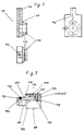
- FIG. 4 shows an exemplary embodiment with a valve hose 66 leading through the inflow line 11.
- the pressure limiting valve 6 and the valve hose 66 are shown enlarged. In fact, the diameter of the valve hose 66 is so small that there is no noticeable flow restriction.
- the pressure relief valve 6 is soldered into the opening 1 in the wall 2 of the inner container 3 .
- the wall 2 of the inner container 3 is designed as a tube sheet 14 , in which the ends of three flat tubes 15 are indicated.
- the valve hose 66 is pushed onto the end of the pressure-limiting valve 6 which projects into the collecting space 8 and has a ring 20 , which enters the inlet line 11 through the opening and extends therein to outside the latent heat store.
- a hose clamp 21 is provided to additionally secure the valve hose 66 on the pressure relief valve 6 .
- the inflow line 11 leaves the latent heat storage through an opening in the outer container 5 and is of course firmly and sealed soldered.
- the opposite end of the pressure relief valve 6 is located in the expansion space 7 , in the uppermost point of the inner container 3 .
- the valve hose 66 emerges outside the latent heat store, for example through a wall breakthrough, to the atmosphere, which was not shown separately in the picture.
- reference numerals that start at 100 were used in the following exemplary embodiment, in which the pressure-limiting valve 106 was not inserted directly into an opening 101 in the wall 102 but instead is seated in an adapter 100 .
- the same elements have reference numbers increased by 100.
- FIG. 5 also shows the side view of the latent heat store, in which the insulation space and the outer container 105 are not shown. Furthermore, the cover that closes the collecting space 108 is missing, so that there is a clear view of the tube sheet 104 , which, as part of the inner container 103 , has the cross-sectional shape of the latent heat store. The lower converging area of the latent heat store or the tube sheet 104 was cut off. The cover, not shown, is connected to the erected edge 109 of the tube sheet 104 over the entire circumference by a solder connection. In the tube sheet 104 there are a large number of elongated openings 110 which have an edge 111 which is solid towards the view side. This edge 111 is used for the soldering connection of the flat tubes, not shown, in the openings 110 .
- the heat transfer medium flows through these flat tubes.
- the flat tubes are inserted with their opposite ends in the same way in the openings 110 in the other tube sheet 104 .
- the storage material a suitable one, is located between the flat tubes Salt that transfers heat to the heat transfer medium or absorbs and stores heat by changing its physical state from solid to liquid and vice versa. Since the latent heat store in the exemplary embodiment shown has an installation position of approximately 55 °, the adapter 100 was inserted at the top with this angle 112 in an opening 101 in the wall 102 of the inner container 103 or the tube sheet 104 .
- the adapter 100 is located on the inside of the container, which is why its outer contours are shown in dashed lines.
- One end 114 of the adapter 100 with the bore 113 is in the uppermost point in the installed position of the inner container 103 , the expansion space 107 .
- the adapter 100 has a laterally molded socket 115 , with which it is soldered into the opening 101 of the tube sheet 104 .
- the details of the adapter 100 are shown in FIG. 6.
- the bore 113 opens into the interior of the bush 115 .
- the bushing 115 receives the pressure limiting valve 106 , which has a connecting piece 121 with a through-bore 120 , as will be described further below, as a result of which the hydraulic connection from the inner container 103 into the collecting space 108 is ensured for the purpose of pressure relief.
- the socket 115 also has a shoulder 116 on the circumference and a circumferential groove 117 , which serves for correct positioning and sealing soldering.
- the details of the pressure relief valve 106 are shown in FIG. 7.
- the pressure relief valve 106 has a valve body 131 which has on one side a connector 121 with a circumferential groove 122 and a sealing ring 123 , with which the valve 106 can be inserted into the socket 115 of the adapter 100 .
- a central through bore 120 passes through the valve body 131 and opens at the other end 125, on which a circumferential projecting edge 130 is incorporated.
- This end 125 of the valve body 131 is enclosed by a valve cap 126 made of rubber-elastic material.
- the valve cap 126 consists of a bottom part 132 and a jacket part 133 , so that an approximately pot-like configuration is produced.
- valve cap 126 On the inside 134 of the valve cap 126 there are channels 135 which extend up to the annular bead 136 which closes off the outer surface 133 . This configuration ensures that the annular bead 136 lifts off the valve body 131 at a fixed opening pressure and the pressure is released. Adhesive forces between valve cap 126 and valve body 131 , which influence the opening security, are almost eliminated.
- valve cap 126 is enclosed by a valve cover 127 of the same shape.
- the valve cover 127 is fixed with the edge 137 of its lateral surface 138 to the collar 124 of the valve body 131 . This connection can be made by pointwise Press on.
- the outer surface 138 also has radial bores 128 which serve for the passage of the outflowing medium.
Landscapes
- Engineering & Computer Science (AREA)
- Physics & Mathematics (AREA)
- Thermal Sciences (AREA)
- Mechanical Engineering (AREA)
- General Engineering & Computer Science (AREA)
- Safety Valves (AREA)
- Central Heating Systems (AREA)
- Filling Or Discharging Of Gas Storage Vessels (AREA)
- Heat-Pump Type And Storage Water Heaters (AREA)
- Quick-Acting Or Multi-Walled Pipe Joints (AREA)
Applications Claiming Priority (4)
| Application Number | Priority Date | Filing Date | Title |
|---|---|---|---|
| DE19540015A DE19540015C2 (de) | 1995-10-27 | 1995-10-27 | Latentwärmespeicher, insbesondere zur Verwendung in einem Kraftfahrzeug |
| DE19540015 | 1995-10-27 | ||
| DE19547619 | 1995-12-20 | ||
| DE19547619A DE19547619C2 (de) | 1995-10-27 | 1995-12-20 | Latentwärmespeicher |
Publications (3)
| Publication Number | Publication Date |
|---|---|
| EP0770844A2 true EP0770844A2 (fr) | 1997-05-02 |
| EP0770844A3 EP0770844A3 (fr) | 1998-03-18 |
| EP0770844B1 EP0770844B1 (fr) | 2001-11-07 |
Family
ID=26019834
Family Applications (1)
| Application Number | Title | Priority Date | Filing Date |
|---|---|---|---|
| EP96117140A Expired - Lifetime EP0770844B1 (fr) | 1995-10-27 | 1996-10-25 | Accumulateur à chaleur latente |
Country Status (4)
| Country | Link |
|---|---|
| EP (1) | EP0770844B1 (fr) |
| AT (1) | ATE208485T1 (fr) |
| DE (3) | DE19540015C2 (fr) |
| DK (1) | DK0770844T3 (fr) |
Cited By (1)
| Publication number | Priority date | Publication date | Assignee | Title |
|---|---|---|---|---|
| EP0916918A2 (fr) | 1997-11-12 | 1999-05-19 | Modine Manufacturing Company | Accumulateur de chaleur |
Citations (3)
| Publication number | Priority date | Publication date | Assignee | Title |
|---|---|---|---|---|
| DD249326A1 (de) | 1986-05-21 | 1987-09-02 | Ba D Ddr Inst F Heizung Lueftu | Vorrichtung zur druckentlastung dynamischer latentwaermespeicher |
| DD269209A1 (de) | 1987-12-21 | 1989-06-21 | Bauakademie Ddr | Vorrichtung zur drucksicherung dynamischer latentwaermespeicher |
| DE4020860A1 (de) | 1990-06-29 | 1993-06-24 | Schatz Oskar | Verfahren zur herstellung eines waermespeichers |
Family Cites Families (4)
| Publication number | Priority date | Publication date | Assignee | Title |
|---|---|---|---|---|
| GB375521A (en) * | 1931-06-05 | 1932-06-30 | Ralph Summerfield Ferguson | Improvements in chemical heating appliances |
| DE2551379A1 (de) * | 1974-11-21 | 1976-05-26 | Winfried Josef Werding | Waermespeicher und seine verwendung |
| DE3031947A1 (de) * | 1980-08-25 | 1982-04-08 | Walter 3549 Wolfhagen Kuntschar | Waermespeicher |
| DD249236A1 (de) * | 1986-05-22 | 1987-09-02 | Boxberg Kraftwerk Veb | Anordnung zum abzug von rohbraunkohle aus einem kesselbunker |
-
1995
- 1995-10-27 DE DE19540015A patent/DE19540015C2/de not_active Expired - Fee Related
- 1995-12-20 DE DE19547619A patent/DE19547619C2/de not_active Expired - Fee Related
-
1996
- 1996-10-25 DE DE59608131T patent/DE59608131D1/de not_active Expired - Fee Related
- 1996-10-25 AT AT96117140T patent/ATE208485T1/de not_active IP Right Cessation
- 1996-10-25 EP EP96117140A patent/EP0770844B1/fr not_active Expired - Lifetime
- 1996-10-25 DK DK96117140T patent/DK0770844T3/da active
Patent Citations (3)
| Publication number | Priority date | Publication date | Assignee | Title |
|---|---|---|---|---|
| DD249326A1 (de) | 1986-05-21 | 1987-09-02 | Ba D Ddr Inst F Heizung Lueftu | Vorrichtung zur druckentlastung dynamischer latentwaermespeicher |
| DD269209A1 (de) | 1987-12-21 | 1989-06-21 | Bauakademie Ddr | Vorrichtung zur drucksicherung dynamischer latentwaermespeicher |
| DE4020860A1 (de) | 1990-06-29 | 1993-06-24 | Schatz Oskar | Verfahren zur herstellung eines waermespeichers |
Cited By (2)
| Publication number | Priority date | Publication date | Assignee | Title |
|---|---|---|---|---|
| EP0916918A2 (fr) | 1997-11-12 | 1999-05-19 | Modine Manufacturing Company | Accumulateur de chaleur |
| EP0916918A3 (fr) * | 1997-11-12 | 2000-05-24 | Modine Manufacturing Company | Accumulateur de chaleur |
Also Published As
| Publication number | Publication date |
|---|---|
| DE19540015A1 (de) | 1997-04-30 |
| DE59608131D1 (de) | 2001-12-13 |
| DE19540015C2 (de) | 1998-03-12 |
| ATE208485T1 (de) | 2001-11-15 |
| DK0770844T3 (da) | 2002-02-25 |
| DE19547619C2 (de) | 1999-02-18 |
| DE19547619A1 (de) | 1997-07-03 |
| EP0770844B1 (fr) | 2001-11-07 |
| EP0770844A3 (fr) | 1998-03-18 |
Similar Documents
| Publication | Publication Date | Title |
|---|---|---|
| DE19750814C5 (de) | Wärmetauscher, insbesondere Ölkühler | |
| EP0370234B2 (fr) | Gorge de remplissage de radiateur avec bouchon | |
| DE2750188A1 (de) | Zurueckziehbarer hydraulischer teleskopischer stossdaempfer | |
| DE19620441A1 (de) | Motor-Aufwärmvorrichtung für ein Fahrzeug und Wärmeisoliereinrichtung | |
| DE102007010393B4 (de) | Wärmeübertrager | |
| DE3203356A1 (de) | Waermeaustauscher | |
| DE2851070B2 (de) | Vorrichtung zum Entlasten des Dichtungspaketes einer Kolbenstange eines hydraulischen Teleskopstoßdämpfers | |
| DE2733057A1 (de) | Vorrichtung zum waermetausch bei salzschmelzenreaktor | |
| DE1912905C3 (de) | Korrosionsbeständiger Kegelhahn | |
| DE3919208C1 (fr) | ||
| DE2248156A1 (de) | Dichtungseinrichtung | |
| EP0770844B1 (fr) | Accumulateur à chaleur latente | |
| DE1188392B (de) | Wellendichtung fuer eine im wesentlichen senkrecht angeordnete Welle | |
| DE3214185A1 (de) | Pumpe, insbesondere fasspumpe | |
| DE1632269B1 (de) | Dichtungsanordnung mit einer dichtungsbuchse fuer die rotor welle einer kontinuierlich arbeitenden zentrifuge | |
| DE2252750A1 (de) | Kuehlerdeckel | |
| DE3017952C2 (de) | Durch periodische Druckspitzen belastetes Lager | |
| DE19548471C1 (de) | Umwälzpumpenaggregat | |
| DE3149688C2 (fr) | ||
| DE2631198C3 (de) | ölfilter mit Filterelement und zwei gleich ausgebildeten Stirnkappen | |
| DE3306553A1 (de) | Oelfilter | |
| EP0260612B1 (fr) | Bouchon pour un réservoir essentiellement rempli d'un liquide | |
| EP0401323B1 (fr) | Palier-guide pour l'enveloppe d'un cylindre de pression | |
| DE10357419B3 (de) | Innengekühlte Stütz- oder Transportrolle | |
| DE1916993A1 (de) | Zahnstangenlenkung fuer Kraftfahrzeuge mit hydraulischer Stossdaempfereinrichtung |
Legal Events
| Date | Code | Title | Description |
|---|---|---|---|
| PUAI | Public reference made under article 153(3) epc to a published international application that has entered the european phase |
Free format text: ORIGINAL CODE: 0009012 |
|
| AK | Designated contracting states |
Kind code of ref document: A2 Designated state(s): AT CH DE DK FR GB IT LI NL SE |
|
| RAP1 | Party data changed (applicant data changed or rights of an application transferred) |
Owner name: LAENGERER & REICH GMBH |
|
| 17P | Request for examination filed |
Effective date: 19971008 |
|
| PUAL | Search report despatched |
Free format text: ORIGINAL CODE: 0009013 |
|
| AK | Designated contracting states |
Kind code of ref document: A3 Designated state(s): AT CH DE DK FR GB IT LI NL SE |
|
| RAP1 | Party data changed (applicant data changed or rights of an application transferred) |
Owner name: MODINE MANUFACTURING COMPANY |
|
| 17Q | First examination report despatched |
Effective date: 20000728 |
|
| GRAG | Despatch of communication of intention to grant |
Free format text: ORIGINAL CODE: EPIDOS AGRA |
|
| GRAG | Despatch of communication of intention to grant |
Free format text: ORIGINAL CODE: EPIDOS AGRA |
|
| GRAG | Despatch of communication of intention to grant |
Free format text: ORIGINAL CODE: EPIDOS AGRA |
|
| GRAH | Despatch of communication of intention to grant a patent |
Free format text: ORIGINAL CODE: EPIDOS IGRA |
|
| GRAH | Despatch of communication of intention to grant a patent |
Free format text: ORIGINAL CODE: EPIDOS IGRA |
|
| GRAA | (expected) grant |
Free format text: ORIGINAL CODE: 0009210 |
|
| AK | Designated contracting states |
Kind code of ref document: B1 Designated state(s): AT CH DE DK FR GB IT LI NL SE |
|
| REF | Corresponds to: |
Ref document number: 208485 Country of ref document: AT Date of ref document: 20011115 Kind code of ref document: T |
|
| REG | Reference to a national code |
Ref country code: CH Ref legal event code: EP |
|
| REF | Corresponds to: |
Ref document number: 59608131 Country of ref document: DE Date of ref document: 20011213 |
|
| REG | Reference to a national code |
Ref country code: GB Ref legal event code: IF02 |
|
| GBT | Gb: translation of ep patent filed (gb section 77(6)(a)/1977) |
Effective date: 20020110 |
|
| REG | Reference to a national code |
Ref country code: DK Ref legal event code: T3 |
|
| PLBE | No opposition filed within time limit |
Free format text: ORIGINAL CODE: 0009261 |
|
| STAA | Information on the status of an ep patent application or granted ep patent |
Free format text: STATUS: NO OPPOSITION FILED WITHIN TIME LIMIT |
|
| PGFP | Annual fee paid to national office [announced via postgrant information from national office to epo] |
Ref country code: GB Payment date: 20021002 Year of fee payment: 7 |
|
| PGFP | Annual fee paid to national office [announced via postgrant information from national office to epo] |
Ref country code: FR Payment date: 20021017 Year of fee payment: 7 |
|
| PGFP | Annual fee paid to national office [announced via postgrant information from national office to epo] |
Ref country code: AT Payment date: 20021018 Year of fee payment: 7 |
|
| PGFP | Annual fee paid to national office [announced via postgrant information from national office to epo] |
Ref country code: SE Payment date: 20021021 Year of fee payment: 7 Ref country code: NL Payment date: 20021021 Year of fee payment: 7 Ref country code: DK Payment date: 20021021 Year of fee payment: 7 |
|
| PGFP | Annual fee paid to national office [announced via postgrant information from national office to epo] |
Ref country code: DE Payment date: 20021029 Year of fee payment: 7 Ref country code: CH Payment date: 20021029 Year of fee payment: 7 |
|
| 26N | No opposition filed | ||
| PG25 | Lapsed in a contracting state [announced via postgrant information from national office to epo] |
Ref country code: GB Free format text: LAPSE BECAUSE OF NON-PAYMENT OF DUE FEES Effective date: 20031025 Ref country code: AT Free format text: LAPSE BECAUSE OF NON-PAYMENT OF DUE FEES Effective date: 20031025 |
|
| PG25 | Lapsed in a contracting state [announced via postgrant information from national office to epo] |
Ref country code: SE Free format text: LAPSE BECAUSE OF NON-PAYMENT OF DUE FEES Effective date: 20031026 |
|
| PG25 | Lapsed in a contracting state [announced via postgrant information from national office to epo] |
Ref country code: LI Free format text: LAPSE BECAUSE OF NON-PAYMENT OF DUE FEES Effective date: 20031031 Ref country code: DK Free format text: LAPSE BECAUSE OF NON-PAYMENT OF DUE FEES Effective date: 20031031 Ref country code: CH Free format text: LAPSE BECAUSE OF NON-PAYMENT OF DUE FEES Effective date: 20031031 |
|
| PG25 | Lapsed in a contracting state [announced via postgrant information from national office to epo] |
Ref country code: NL Free format text: LAPSE BECAUSE OF NON-PAYMENT OF DUE FEES Effective date: 20040501 Ref country code: DE Free format text: LAPSE BECAUSE OF NON-PAYMENT OF DUE FEES Effective date: 20040501 |
|
| EUG | Se: european patent has lapsed | ||
| REG | Reference to a national code |
Ref country code: DK Ref legal event code: EBP |
|
| REG | Reference to a national code |
Ref country code: CH Ref legal event code: PL |
|
| GBPC | Gb: european patent ceased through non-payment of renewal fee |
Effective date: 20031025 |
|
| PG25 | Lapsed in a contracting state [announced via postgrant information from national office to epo] |
Ref country code: FR Free format text: LAPSE BECAUSE OF NON-PAYMENT OF DUE FEES Effective date: 20040630 |
|
| NLV4 | Nl: lapsed or anulled due to non-payment of the annual fee |
Effective date: 20040501 |
|
| REG | Reference to a national code |
Ref country code: FR Ref legal event code: ST |
|
| PG25 | Lapsed in a contracting state [announced via postgrant information from national office to epo] |
Ref country code: IT Free format text: LAPSE BECAUSE OF NON-PAYMENT OF DUE FEES Effective date: 20051025 |