EP0770844A2 - Latent heat storage - Google Patents
Latent heat storage Download PDFInfo
- Publication number
- EP0770844A2 EP0770844A2 EP96117140A EP96117140A EP0770844A2 EP 0770844 A2 EP0770844 A2 EP 0770844A2 EP 96117140 A EP96117140 A EP 96117140A EP 96117140 A EP96117140 A EP 96117140A EP 0770844 A2 EP0770844 A2 EP 0770844A2
- Authority
- EP
- European Patent Office
- Prior art keywords
- valve
- latent heat
- inner container
- bore
- opening
- Prior art date
- Legal status (The legal status is an assumption and is not a legal conclusion. Google has not performed a legal analysis and makes no representation as to the accuracy of the status listed.)
- Granted
Links
Images


Classifications
-
- B—PERFORMING OPERATIONS; TRANSPORTING
- B60—VEHICLES IN GENERAL
- B60H—ARRANGEMENTS OF HEATING, COOLING, VENTILATING OR OTHER AIR-TREATING DEVICES SPECIALLY ADAPTED FOR PASSENGER OR GOODS SPACES OF VEHICLES
- B60H1/00—Heating, cooling or ventilating [HVAC] devices
- B60H1/00492—Heating, cooling or ventilating [HVAC] devices comprising regenerative heating or cooling means, e.g. heat accumulators
-
- F—MECHANICAL ENGINEERING; LIGHTING; HEATING; WEAPONS; BLASTING
- F28—HEAT EXCHANGE IN GENERAL
- F28D—HEAT-EXCHANGE APPARATUS, NOT PROVIDED FOR IN ANOTHER SUBCLASS, IN WHICH THE HEAT-EXCHANGE MEDIA DO NOT COME INTO DIRECT CONTACT
- F28D20/00—Heat storage plants or apparatus in general; Regenerative heat-exchange apparatus not covered by groups F28D17/00 or F28D19/00
- F28D20/02—Heat storage plants or apparatus in general; Regenerative heat-exchange apparatus not covered by groups F28D17/00 or F28D19/00 using latent heat
- F28D20/021—Heat storage plants or apparatus in general; Regenerative heat-exchange apparatus not covered by groups F28D17/00 or F28D19/00 using latent heat the latent heat storage material and the heat-exchanging means being enclosed in one container
-
- F—MECHANICAL ENGINEERING; LIGHTING; HEATING; WEAPONS; BLASTING
- F01—MACHINES OR ENGINES IN GENERAL; ENGINE PLANTS IN GENERAL; STEAM ENGINES
- F01P—COOLING OF MACHINES OR ENGINES IN GENERAL; COOLING OF INTERNAL-COMBUSTION ENGINES
- F01P11/00—Component parts, details, or accessories not provided for in, or of interest apart from, groups F01P1/00 - F01P9/00
- F01P11/14—Indicating devices; Other safety devices
- F01P2011/205—Indicating devices; Other safety devices using heat-accumulators
-
- Y—GENERAL TAGGING OF NEW TECHNOLOGICAL DEVELOPMENTS; GENERAL TAGGING OF CROSS-SECTIONAL TECHNOLOGIES SPANNING OVER SEVERAL SECTIONS OF THE IPC; TECHNICAL SUBJECTS COVERED BY FORMER USPC CROSS-REFERENCE ART COLLECTIONS [XRACs] AND DIGESTS
- Y02—TECHNOLOGIES OR APPLICATIONS FOR MITIGATION OR ADAPTATION AGAINST CLIMATE CHANGE
- Y02E—REDUCTION OF GREENHOUSE GAS [GHG] EMISSIONS, RELATED TO ENERGY GENERATION, TRANSMISSION OR DISTRIBUTION
- Y02E60/00—Enabling technologies; Technologies with a potential or indirect contribution to GHG emissions mitigation
- Y02E60/14—Thermal energy storage
Definitions
- the invention relates to a latent heat store, preferably for use in a motor vehicle, with the features of the preamble of claim 1.
- the latent heat accumulator equipped with the features of the preamble is known from DE-PS 40 20 860.
- the latent heat accumulator known from DD-PS 249 326 has an expandable area in its inner container which can absorb the increasing pressures.
- the solution known from DD-PS 269 209 is a latent heat storage device with direct contact between the storage material and the heat transfer medium.
- a pressure pipe is led through the insulation from the expansion space and is connected outside the latent heat store to one or more pressure relief valves and a collecting vessel for the escaping storage material.
- This construction significantly increases the cost of the latent heat storage and, for certain applications, for example in the motor vehicle sector, has intolerable disadvantages with regard to the quality of the thermal insulation.
- the heat loss caused by the pressure pipe enhances the high-quality properties, for example vacuum insulation, almost on. Furthermore, there is no space in motor vehicles for accommodating the collecting vessel with the associated equipment. Overall, there are a large number of proposed solutions in this area.
- the object of the invention is to provide an additional variant for pressure relief in latent heat stores with simple and inexpensive means, which also opens up the possibility of no longer having to build latent heat stores with such high pressure stability and which is significantly improved with regard to the limitation of heat losses .
- a pressure relief valve is directly sealed in an opening in the wall of the inner container so that one end of the pressure relief valve projects into the expansion space of the inner container and the other end opens into the collecting space of the heat transfer medium.
- the pressure relief valve protects the inner container and thus the entire latent heat accumulator from excessively high pressures which may destroy the latent heat accumulator.
- the pressure stability of the latent heat storage device may be lower in the future, which makes cheaper designs possible.
- the amount of the substance released into the heat transfer medium is so small that there is no need to fear a harmful, for example corrosive, effect.
- the pressure reduction takes place in a collecting space of the heat transfer medium.
- a pressure relief valve is used, which works in principle like a hose valve, which, although it allows the outflow from the inner container when a certain pressure value is exceeded, certainly prevents the heat transfer medium from entering the storage space or coming into contact with the storage material. (Claim 3) It goes without saying that the elasticity and preload of the hose section determine the pressure value at which the valve opens.
- the pressure relief valve is preferably soldered directly into the opening in the wall of the inner container.
- the end of the pressure relief valve with the central bore is in the expansion chamber, in the uppermost point of the inner container in the installed position and the opposite end of the pressure relief valve protrudes into the collecting area of the heat transfer medium.
- the tube piece is pushed over the valve body and covers the radial bore adjoining the axial bore.
- the sliding down of the hose section can also be prevented by the end of the hose section abutting, for example, a wall of the latent heat store.
- the special arrangement of the pressure relief valve should be done in such a way that it can be prevented with certainty that storage material itself can get into the valve, which could impair the function. It has been found that an arrangement inclined both to the horizontal and to the vertical with an angle of approximately 30 ° best meets this requirement.
- the bore diameter of approximately 2 mm leads on the one hand to very good valve action and on the other hand prevents the ingress of storage material into the valve.
- an angled valve body can also be used, the end of which extends into the expansion space and protrudes as far as possible in the installed position.
- Claim 7 contains another variant, according to which it is provided to bring about the pressure reduction to the atmosphere in which the inlet or the outlet line is used to derive the pressure.
- This has the advantage that no additional measures to avoid thermal bridges within the insulation are necessary.
- the pressure relief valve placed in the opening in the wall of the inner container carries a valve hose on the end projecting into the collecting space, said valve hose being guided practically coaxially through the inlet or outlet line to outside of the latent heat store.
- the valve hose is connected to the atmosphere, for example, by a further breakthrough in the wall of the line.
- the valve hose is a hose of small diameter, which does not constitute a flow restriction worth mentioning for the heat transfer medium.
- Claim 8 contains a further alternative to claims 1 to 7. Thereafter, the pressure is also released to the atmosphere, but in that at least one further opening is provided in the outer container.
- the pressure relief valve in this case is in the opening in the outer container.
- Claims 9 to 13 relate to a next independent variant, which also improves the manufacturability and the reliable functioning of the latent heat store.
- the pressure relief valve is not inserted directly into the opening in the wall, but instead a receiving part called adapter is interposed, the bore in the adapter being in hydraulic connection with the through bore of the pressure relief valve.
- the adapter does not have to be installed, particularly soldered, directly in the radius of the wall of the inner container, but sits in the still flat section, one end protruding with the bore into the expansion space. In terms of production technology, this is not only easier to do, but also improves the soldering quality.
- the manufacturing process is also considerably simplified by the fact that the pressure relief valve is no longer firmly soldered in, but is only sealed by means of a seal in the side-mounted socket of the adapter.
- the laterally arranged socket ensures that the adapter can be optimally arranged and soldered in such a way that its one end with the bore reaches the top point in the expansion space without the soldering position deteriorating.
- the hole extends from this uppermost point to the inside of the bush.
- the through bore through the valve body is in hydraulic connection with the aforementioned bore, since the nozzle of the valve body is located in the socket of the adapter.
- the design of the pressure relief valve itself, according to claims 11 to 13 also leads to greater reliability of operation, in particular because the contact area between the valve cap and the valve body has been significantly reduced, which leads to lower adhesive forces between the valve cap and the valve body and thus to a greater opening security in the event of overpressure.
- the valve cover attached to the collar of the valve body preferably by pressing or prying, has a protective function against lifting or slipping off the valve cap, in the event of unforeseen high pressure.
- Fig. 1 shows the latent heat storage, which is provided for installation in a motor vehicle and in which the cooling water of the engine is used as a heat transfer medium.
- the latent heat store consists of an outer container 5 , which includes the inner container 3 .
- the space between the inner container 3 and the outer container 5 is a vacuum insulation space which is filled with a suitable insulation powder, for which the filling opening 9 is used, which is then closed.
- the latent heat store is drawn with the cover 10 still open, on which the inflow and outflow lines 11 ; 12 are arranged.
- the open lid 10 gives a clear view of the wall 2 of the inner container 3 , from which the end 62 of the pressure relief valve 6 projects into the collecting space 8 of the cooling water.
- the wall 2 of the inner container 3 is designed as a tube sheet 14 which has a plurality of elongated openings in which the ends of the flat tubes 15 are soldered firmly and sealingly.
- the same design is present at the other end of the latent heat storage, not shown.
- the hot cooling water flows through the inflow line 11 into the collecting space 8 in order to be distributed there over the flat tubes 15 .
- the cooling water flows through the flat tubes 15 passing through the inner container 3 in the direction of the other end of the latent heat store, is deflected by a partition wall 16 in the cover 17 and flows back. Since there is also a partition 16 in the cover 10 , a meandering flow through the latent heat store can take place, which ensures good heat absorption or heat dissipation.
- the cooling water flows back into the cooling circuit via the drain line 12 .
- the inadmissibly high pressure that builds up during operation of the latent heat store is reduced by the pressure relief valve 6 and discharged into the collecting space 8 of the cooling water.
- Fig. 2 shows the soldered pressure relief valve 6 in the wall 2 , which is represented by the tube sheet 14 .
- the outer container 5 and the isolation space have been omitted for simplification.
- the arrangement is provided at the highest point of the inner container 3 and is designed such that the end 61 of the pressure relief valve 6 with the central bore 64 projects into the expansion space 7 of the inner container 3 . This is sufficiently above the level of the storage material.
- the pressure relief valve 6 is installed inclined at approximately 30 ° to the horizontal.
- the other end 62 of the pressure relief valve 6 is located in the collecting space 8 of the cooling water.
- FIG. 2 also shows that a radial bore 65 is introduced approximately at the end of the central 2 mm bore 64 , which leads to the circumference of the metal cylinder 63 .
- a piece of hose 66 is pushed over the circumference of the metal cylinder 63 , whereby the functioning of a hose valve is achieved.
- the elasticity of the hose section 66 determines the pressure at which the pressure reduction begins. Obviously, this is already the case at such a pressure, in which no harmful effects yet occur on the inner container 3 or the latent heat store.
- the hose section 66 prevents the cooling water from entering the inner container 3 .
- any axial migration of the tube piece 66 on the metal cylinder 63 is prevented by the special installation position shown, because the tube piece 66 abuts a wall of the latent heat store.
- a ring could also be provided on the metal cylinder 63 , over which the tube piece 66 is pushed.
- an opening 1 is in both the wall 2 of the inner container 3 and in the wall of the outer container 5 ; 4 provided.
- the insulation space is bridged by means of a short pipeline 18 , which is sealingly fastened in the opening 1 .
- the pressure relief valve 6 is firmly soldered into the opening 4 in the wall of the outer container 5 .
- the pipeline 18 opens into the pressure relief valve 6 .
- the pressure relief valve 6 can be identical to the valve already described.
- a collar 19 can be provided on the metal cylinder 63 , which allows a better solder connection.
- FIG. 4 shows an exemplary embodiment with a valve hose 66 leading through the inflow line 11.
- the pressure limiting valve 6 and the valve hose 66 are shown enlarged. In fact, the diameter of the valve hose 66 is so small that there is no noticeable flow restriction.
- the pressure relief valve 6 is soldered into the opening 1 in the wall 2 of the inner container 3 .
- the wall 2 of the inner container 3 is designed as a tube sheet 14 , in which the ends of three flat tubes 15 are indicated.
- the valve hose 66 is pushed onto the end of the pressure-limiting valve 6 which projects into the collecting space 8 and has a ring 20 , which enters the inlet line 11 through the opening and extends therein to outside the latent heat store.
- a hose clamp 21 is provided to additionally secure the valve hose 66 on the pressure relief valve 6 .
- the inflow line 11 leaves the latent heat storage through an opening in the outer container 5 and is of course firmly and sealed soldered.
- the opposite end of the pressure relief valve 6 is located in the expansion space 7 , in the uppermost point of the inner container 3 .
- the valve hose 66 emerges outside the latent heat store, for example through a wall breakthrough, to the atmosphere, which was not shown separately in the picture.
- reference numerals that start at 100 were used in the following exemplary embodiment, in which the pressure-limiting valve 106 was not inserted directly into an opening 101 in the wall 102 but instead is seated in an adapter 100 .
- the same elements have reference numbers increased by 100.
- FIG. 5 also shows the side view of the latent heat store, in which the insulation space and the outer container 105 are not shown. Furthermore, the cover that closes the collecting space 108 is missing, so that there is a clear view of the tube sheet 104 , which, as part of the inner container 103 , has the cross-sectional shape of the latent heat store. The lower converging area of the latent heat store or the tube sheet 104 was cut off. The cover, not shown, is connected to the erected edge 109 of the tube sheet 104 over the entire circumference by a solder connection. In the tube sheet 104 there are a large number of elongated openings 110 which have an edge 111 which is solid towards the view side. This edge 111 is used for the soldering connection of the flat tubes, not shown, in the openings 110 .
- the heat transfer medium flows through these flat tubes.
- the flat tubes are inserted with their opposite ends in the same way in the openings 110 in the other tube sheet 104 .
- the storage material a suitable one, is located between the flat tubes Salt that transfers heat to the heat transfer medium or absorbs and stores heat by changing its physical state from solid to liquid and vice versa. Since the latent heat store in the exemplary embodiment shown has an installation position of approximately 55 °, the adapter 100 was inserted at the top with this angle 112 in an opening 101 in the wall 102 of the inner container 103 or the tube sheet 104 .
- the adapter 100 is located on the inside of the container, which is why its outer contours are shown in dashed lines.
- One end 114 of the adapter 100 with the bore 113 is in the uppermost point in the installed position of the inner container 103 , the expansion space 107 .
- the adapter 100 has a laterally molded socket 115 , with which it is soldered into the opening 101 of the tube sheet 104 .
- the details of the adapter 100 are shown in FIG. 6.
- the bore 113 opens into the interior of the bush 115 .
- the bushing 115 receives the pressure limiting valve 106 , which has a connecting piece 121 with a through-bore 120 , as will be described further below, as a result of which the hydraulic connection from the inner container 103 into the collecting space 108 is ensured for the purpose of pressure relief.
- the socket 115 also has a shoulder 116 on the circumference and a circumferential groove 117 , which serves for correct positioning and sealing soldering.
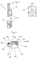
- the details of the pressure relief valve 106 are shown in FIG. 7.
- the pressure relief valve 106 has a valve body 131 which has on one side a connector 121 with a circumferential groove 122 and a sealing ring 123 , with which the valve 106 can be inserted into the socket 115 of the adapter 100 .
- a central through bore 120 passes through the valve body 131 and opens at the other end 125, on which a circumferential projecting edge 130 is incorporated.
- This end 125 of the valve body 131 is enclosed by a valve cap 126 made of rubber-elastic material.
- the valve cap 126 consists of a bottom part 132 and a jacket part 133 , so that an approximately pot-like configuration is produced.
- valve cap 126 On the inside 134 of the valve cap 126 there are channels 135 which extend up to the annular bead 136 which closes off the outer surface 133 . This configuration ensures that the annular bead 136 lifts off the valve body 131 at a fixed opening pressure and the pressure is released. Adhesive forces between valve cap 126 and valve body 131 , which influence the opening security, are almost eliminated.
- valve cap 126 is enclosed by a valve cover 127 of the same shape.
- the valve cover 127 is fixed with the edge 137 of its lateral surface 138 to the collar 124 of the valve body 131 . This connection can be made by pointwise Press on.
- the outer surface 138 also has radial bores 128 which serve for the passage of the outflowing medium.
Landscapes
- Engineering & Computer Science (AREA)
- Physics & Mathematics (AREA)
- Thermal Sciences (AREA)
- Mechanical Engineering (AREA)
- General Engineering & Computer Science (AREA)
- Central Heating Systems (AREA)
- Safety Valves (AREA)
- Filling Or Discharging Of Gas Storage Vessels (AREA)
- Heat-Pump Type And Storage Water Heaters (AREA)
- Quick-Acting Or Multi-Walled Pipe Joints (AREA)
Abstract
Description
Die Erfindung betrifft einen Latentwärmespeicher, vorzugsweise zur Verwendung in einem Kraftfahrzeug, mit den Merkmalen des Oberbegriffes des Anspruches 1.The invention relates to a latent heat store, preferably for use in a motor vehicle, with the features of the preamble of
Der mit den Merkmalen des Oberbegriffes ausgestattete Latentwärmespeicher ist aus der DE-PS 40 20 860 bekannt.The latent heat accumulator equipped with the features of the preamble is known from DE-PS 40 20 860.
Bei Latentwärmespeichern hat es sich neuerdings herausgestellt, daß sich während des Betriebes im Innenbehälter, bedingt durch die ständigen Ladungswechsel, die mit Verflüssigung und Verfestigung des Speichermaterials einhergehen, Drucke entwickeln, die sich im Laufe der Zeit bis in unzulässige Bereiche akkumulieren können.With latent heat storage, it has recently been found that during operation in the inner container, due to the constant charge changes associated with liquefaction and solidification of the storage material, pressures develop which can accumulate over the course of time into impermissible areas.
Das an sich bekannte Problem des sich durch die Volumenvergrößerung aufbauenden Druckes, hat man bisher auf unterschiedliche Art gelöst. Beispielsweise hat der aus der DD-PS 249 326 bekanntgewordene Latentwärmespeicher in seinem Innenbehälter einen dehnbaren Bereich, der die wachsenden Drücke aufnehmen kann.The problem known per se of the pressure building up as a result of the increase in volume has hitherto been solved in different ways. For example, the latent heat accumulator known from DD-PS 249 326 has an expandable area in its inner container which can absorb the increasing pressures.
Andere Lösungen sind mit einem sehr stabilen Innenbehälter ausgerüstet, der hohe Drücke kompensieren kann. Dies führt allerdings zu hohem Gewicht und zu höheren Kosten. Zusätzlich wird die einzufüllende Menge des Speichermaterials so bemessen, daß ein Expansionsraum im Innenbehälter frei bleibt, der dann zur Druckentlastung beiträgt. Es ist auch bekannt, das Speichermaterial mit einer solch hohen Temperatur einzufüllen, die im Betrieb nicht mehr erreicht wird, so daß ebenfalls ein Expansionsraum verbleibt. Dies ist jedoch fertigungstechnisch nicht immer von Vorteil und es ist nicht ausgeschlossen, daß durch Störungen die erwartete Höchsttemperatur doch überschritten wird.Other solutions are equipped with a very stable inner container that can compensate for high pressures. However, this leads to high weight and higher costs. In addition, the amount of storage material to be filled is dimensioned so that an expansion space in the inner container remains free, which then contributes to pressure relief. It is also known to fill the storage material with such a high temperature that is no longer reached during operation, so that an expansion space also remains. However, this is not always advantageous from a manufacturing point of view and it cannot be ruled out that the expected maximum temperature may be exceeded due to malfunctions.
Man hat auch einzelne flexible Hüllen vorgeschlagen, in die das Speichermaterial eingefüllt wird, um das Druckproblem zu lösen.Individual flexible sleeves have also been proposed, into which the storage material is filled in order to solve the printing problem.
Schließlich hat man auch schon bei Latentwärmespeichern das Druckproblem durch das Vorsehen von Überdruckventilen zu bekämpfen versucht. Bei der aus der DD-PS 269 209 bekannten Lösung handelt es sich um einen Latentwärmespeicher, mit direktem Kontakt zwischen dem Speichermaterial und dem Wärmeträgermedium. Es ist ein Druckrohr vom Expansionsraum ausgehend durch die Isolation geführt und außerhalb des Latentwärmespeichers mit einem oder mehreren Überdruckventilen sowie einem Auffanggefäß für das entweichende Speichermaterial verbunden. Diese Konstruktion verteuert den Latentwärmespeicher wesentlich und hat für bestimmte Anwendungsfälle, beispielsweise im Kraftfahrzeugbereich, untragbare Nachteile, hinsichtlich der Qualität der Wärmeisolation. Der durch das Druckrohr verursachte Wärmeverlust hebt die hochwertigen Eigenschaften, beispielsweise einer Vakuumisolation, nahezu auf. Ferner ist in Kraftfahrzeugen kein Raum zur Unterbringung des Auffanggefäßes mit den dazugehörigen Apparaturen vorhanden. Insgesamt gibt es auf diesem Gebiet eine Vielzahl von Lösungsvorschlägen.After all, attempts have already been made to combat the pressure problem in the case of latent heat stores by providing pressure relief valves. The solution known from DD-PS 269 209 is a latent heat storage device with direct contact between the storage material and the heat transfer medium. A pressure pipe is led through the insulation from the expansion space and is connected outside the latent heat store to one or more pressure relief valves and a collecting vessel for the escaping storage material. This construction significantly increases the cost of the latent heat storage and, for certain applications, for example in the motor vehicle sector, has intolerable disadvantages with regard to the quality of the thermal insulation. The heat loss caused by the pressure pipe enhances the high-quality properties, for example vacuum insulation, almost on. Furthermore, there is no space in motor vehicles for accommodating the collecting vessel with the associated equipment. Overall, there are a large number of proposed solutions in this area.
Die Aufgabe der Erfindung besteht darin, mit einfachen und kostengünstigen Mitteln eine zusätzliche Variante zur Druckentlastung in Latentwärmespeichern zur Verfügung zu stellen, die auch die Möglichkeit eröffnet, Latentwärmespeicher nicht mehr mit solch hoher Druckstabilität bauen zu müssen und die hinsichtlich der Begrenzung von Wärmeverlusten wesentlich verbessert ist.The object of the invention is to provide an additional variant for pressure relief in latent heat stores with simple and inexpensive means, which also opens up the possibility of no longer having to build latent heat stores with such high pressure stability and which is significantly improved with regard to the limitation of heat losses .
Diese Aufgabe wird in Verbindung mit den Merkmalen des Oberbegriffes erfindungsgemäß überraschend einfach in einer ersten Variante dadurch gelöst, daß ein Druckbegrenzungsventil unmittelbar in einem Durchbruch in der Wandung des Innenbehälters abdichtend befestigt ist, so daß das eine Ende des Druckbegrenzungsventils in den Expansionsraum des Innenbehälters ragt und das andere Ende im Sammelraum des Wärmeträgermediums mündet. Das Druckbegrenzungsventil schützt den Innenbehälter und damit den gesamten Latentwärmespeicher vor zu hohen und gegebenenfalls den Latentwärmespeicher zerstörenden Drucken. Die Druckstabilität des Latentwärmespeichers kann zukünftig geringer sein, wodurch billigere Bauweisen möglich werden.This object is achieved in connection with the features of the preamble surprisingly simply according to the invention in a first variant in that a pressure relief valve is directly sealed in an opening in the wall of the inner container so that one end of the pressure relief valve projects into the expansion space of the inner container and the other end opens into the collecting space of the heat transfer medium. The pressure relief valve protects the inner container and thus the entire latent heat accumulator from excessively high pressures which may destroy the latent heat accumulator. The pressure stability of the latent heat storage device may be lower in the future, which makes cheaper designs possible.
Sämtliche weitere in den Patentansprüchen enthaltenen Merkmale sollen als an dieser Stelle ausdrücklich erwähnt gelten und könnten sich als erfindungswesentlich herausstellen. Nach der Variante der Ansprüche 1 bis 6 erfolgt der Druckabbau dadurch, daß bei Überschreitung des zulässigen Druckes der Druckabbau in das Wärmeträgermedium erfolgt.All other features contained in the claims are to be expressly mentioned at this point and could prove to be essential to the invention. According to the variant of
Dabei hat sich herausgestellt, daß die Menge des in das Wärmeträgermedium abgegebenen Stoffes so gering ist, daß eine schädliche, etwa korrosive Wirkung nicht befürchtet werden muß. Der Druckabbau erfolgt in einen Sammelraum des Wärmeträgermediums. Dazu ist ein Druckbegrenzungsventil eingesetzt, daß prinzipiell wie ein Schlauchventil arbeitet, das zwar das Ausströmen aus dem Innenbehälter bei Überschreitung eines bestimmten Druckwertes gestattet, aber mit Sicherheit verhindert, daß das Wärmeträgermedium in den Speicherraum gelangt, bzw. in Kontakt mit dem Speichermaterial kommt. (Anspruch 3) Dabei versteht sich, daß die Elastizität und Vorspannung des Schlauchstückes bestimmen, bei welchem Druckwert das Ventil öffnet.It has been found that the amount of the substance released into the heat transfer medium is so small that there is no need to fear a harmful, for example corrosive, effect. The pressure reduction takes place in a collecting space of the heat transfer medium. For this purpose, a pressure relief valve is used, which works in principle like a hose valve, which, although it allows the outflow from the inner container when a certain pressure value is exceeded, certainly prevents the heat transfer medium from entering the storage space or coming into contact with the storage material. (Claim 3) It goes without saying that the elasticity and preload of the hose section determine the pressure value at which the valve opens.
Gemäß Anspruch 2 ist das Druckbegrenzungsventil vorzugsweise direkt in dem Durchbruch der Wandung des Innenbehälters eingelötet. Dabei befindet sich das Ende des Druckbegrenzungsventils mit der zentrischen Bohrung im Expansionsraum, im in Einbaulage obersten Punkt des Innenbehälters und das entgegengesetzte Ende des Druckbegrenzungsventils ragt in den Sammelraum des Wärmeträgermediums. An diesem Ende ist das Schlauchstück über den Ventilkörper geschoben und deckt die an die axiale Bohrung anschließende radiale Bohrung ab. Ein besonderer Vorteil dieser Ventilkonstruktion besteht darin, daß mit einer ausreichend groß gewählten Länge des Schlauchstückes (Abdichtlänge) eine hohe Sicherheit gegen Leckagen erzielt werden kann. Ferner kann durch das Vorsehen einer oder mehrerer Ringe um den Ventilkörper erreicht werden, daß das Schlauchstück im Betrieb nicht vom Ventilkörper herunterrutscht. Je nach den speziellen örtlichen Einbauverhältnissen, kann das Herunterrutschen des Schlauchstückes auch dadurch verhindert werden, daß das Ende des Schlauchstückes beispielsweise an eine Wand des Latentwärmespeichers anstößt. Die spezielle Anordnung des Druckbegrenzungsventils sollte so erfolgen, daß mit einiger Sicherheit verhindert wird, daß Speichermaterial selbst in das Ventil gelangen kann, wodurch die Funktion beeinträchtigt werden könnte. Dazu hat sich herausgestellt, daß eine sowohl zur Horizontalen als auch zur Vertikalen mit einem Winkel von etwa 30° geneigte Anordnung dieser Forderung am besten Rechnung trägt.According to
Darüber hinaus hat es sich gezeigt, daß der Bohrungsdurchmesser von etwa 2 mm einerseits zu sehr guter Ventilwirkung führt und andererseits das Eindringen von Speichermaterial in das Ventil verhindert. Außerdem kann auch ein abgewinkelter Ventilkörper eingesetzt werden, dessen in den Expansionsraum reichendes Ende in Einbaulage möglichst weit nach oben ragt.In addition, it has been shown that the bore diameter of approximately 2 mm leads on the one hand to very good valve action and on the other hand prevents the ingress of storage material into the valve. In addition, an angled valve body can also be used, the end of which extends into the expansion space and protrudes as far as possible in the installed position.
Anspruch 7 enthält eine andere Variante, wonach vorgesehen ist, den Druckabbau an die Atmosphäre zu bewerkstelligen, in dem die Zu-oder die Abflußleitung zur Ableitung des Druckes verwendet wird. Das hat den Vorteil, daß keine zusätzlichen Maßnahmen zur Vermeidung von Wärmebrücken innerhalb der Isolation notwendig sind. Erreicht wird das dadurch, daß das im Durchbruch der Wandung des Innenbehälters placierte Druckbegrenzungsventil auf dem in den Sammelraum ragendem Ende einen Ventilschlauch trägt, der praktisch koaxial durch die Zu-oder die Abflußleitung bis nach außerhalb des Latentwärmespeichers geführt ist. Dort ist der Ventilschlauch beispielsweise durch einen weiteren Durchbruch in der Wandung der Leitung in Verbindung zur Atmosphäre. Bei dem Ventilschlauch handelt es sich um einen Schlauch geringen Durchmessers, der keine erwähnenswerte Strömungsbehinderung für das Wärmeträgermedium darstellt.
Eine weitere Alternative zu den Ansprüchen 1 bis 7 enthält der Anspruch 8. Danach wird der Druck ebenfalls an die Atmosphäre abgeführt, jedoch dadurch, daß mindestens ein weiterer Durchbruch in dem Außenbehälter vorgesehen ist. Das Druckbegrerzungsventil befindet sich in diesem Fall in dem Durchbruch im Außenbehälter. Es ist selbstverständlich, daß durch den Einsatz von Werkstoffen geringer Wärmeleitfähigkeit dafür Sorge getragen wird, daß sich möglichst keine oder nur geringe Wärmebrücken bilden, die die Isolationswirkung beeinträchtigen könnten. Bezüglich der Begrenzung der Wärmeverluste durch Wärmeleitung stellt die Alternative gemäß Anspruch 8 die etwas schlechtere Alternative dar. Sie hat jedoch Vorteile aus fertigungstechnischer Sicht.
Die Ansprüche 9 bis 13 betreffen eine nächste eigenständige Variante, die darüber hinaus die Herstellbarkeit und die zuverlässige Funktionsweise des Latentwärmespeichers verbessert.Claims 9 to 13 relate to a next independent variant, which also improves the manufacturability and the reliable functioning of the latent heat store.
Dies geschieht dadurch, daß das Druckbegrenzungsventil nicht direkt in dem Durchbruch der Wandung eingesetzt ist, sondern ein als Adapter bezeichnetes Aufnahmeteil zwischengefügt wurde, wobei die Bohrung im Adapter mit der Durchgangsbohrung des Druckbegrenzungsventils in hydraulischer Verbindung ist. Der Adapter muß nicht unmittelbar im Radius der Wandung des Innenbehälters eingebaut, insbesondere eingelötet werden, sondern sitzt im noch ebenen Abschnitt, wobei das eine Ende mit der Bohrung in den Expansionsraum ragt. Das ist fertigungstechnisch nicht nur einfacher zu bewerkstelligen sondern verbessert auch die Lötqualität. Wesentlich vereinfacht wird der Fertigungsprozeß auch dadurch, daß das Druckbegrenzungsventil nicht mehr fest eingelötet ist sondern nur mittels einer Dichtung abgedichtet in der seitlich angeordneten Buchse des Adapters steckt. Die seitlich angeordnete Buchse gewährleistet, daß der Adapter optimal so angeordnet und eingelötet werden kann, daß sein eines Ende mit der Bohrung den obersten Punkt im Expansionsraum erreicht, ohne daß sich die Lötposition verschlechtert. Die Bohrung erstreckt sich von diesem obersten Punkt bis in das Innere der Buchse. Die Durchgangsbohrung durch den Ventilkörper ist mit der zuvor genannten Bohrung in hydraulischer Verbindung, da der Stutzen des Ventilkörpers sich in der Buchse des Adapters befindet.
Die Ausbildung des Druckbegrenzungsventils selbst, gemäß den Ansprüchen 11 bis 13, führt ebenfalls zu höherer Zuverlässigkeit der Funktionsweise, insbesondere deshalb, weil die Kontaktfläche zwischen der Ventilkappe und dem Ventilkörper wesentlich reduziert wurde, was zu geringeren Adhäsionskräften zwischen Ventilkappe und Ventilkörper führt und damit zu einer größeren Öffnungssicherheit bei Überdruck. Der am Bund des Ventilkörpers, vorzugsweise durch Anpressen oder Anstemmen, befestigte Ventildeckel hat eine Schutzfünktion gegen Abheben oder Abrutschen der Ventilkappe, im Fall von unvorhergesehen hohem Druck.This is done in that the pressure relief valve is not inserted directly into the opening in the wall, but instead a receiving part called adapter is interposed, the bore in the adapter being in hydraulic connection with the through bore of the pressure relief valve. The adapter does not have to be installed, particularly soldered, directly in the radius of the wall of the inner container, but sits in the still flat section, one end protruding with the bore into the expansion space. In terms of production technology, this is not only easier to do, but also improves the soldering quality. The manufacturing process is also considerably simplified by the fact that the pressure relief valve is no longer firmly soldered in, but is only sealed by means of a seal in the side-mounted socket of the adapter. The laterally arranged socket ensures that the adapter can be optimally arranged and soldered in such a way that its one end with the bore reaches the top point in the expansion space without the soldering position deteriorating. The hole extends from this uppermost point to the inside of the bush. The through bore through the valve body is in hydraulic connection with the aforementioned bore, since the nozzle of the valve body is located in the socket of the adapter.
The design of the pressure relief valve itself, according to
Nachfolgend wird die Erfindung in Ausführungsbeispielen erläutert, wozu auf die Zeichnungen Bezug genommen wird.The invention is explained below in exemplary embodiments, for which reference is made to the drawings.
Es zeigen
- Fig. 1
- Prinzipdarstellung des Latentwärmespeichers mit Druckbegrenzungsventil
- Fig. 2
- Ausschnitt, der das Druckbegrenzungsventil zwischen Expansionsraum des Innenbehälters und Sammelraum des Wärmeträgermediums zeigt.
- Fig.3
- Ausführungsvariante mit Druckabbau in die Atmosphäre über einen zweiten Durchbruch im Außenbehälter
- Fig. 4
- Ausführungsvariante mit einem Ventilschlauch in der Zu-oder Abflußleitung
- Fig. 5
- Rohrboden eines Latentwärmespeichers mit eingebautem Adapter
- Fig. 6
- Adapter als Einzelteil in mehreren Ansichten
- Fig. 7
- Druckbegrenzungsventil der Adapter-Variante im Teilschnitt
- Fig. 1
- Schematic diagram of the latent heat storage with pressure relief valve
- Fig. 2
- Detail showing the pressure relief valve between the expansion space of the inner container and the collection space of the heat transfer medium.
- Fig. 3
- Design variant with pressure relief into the atmosphere via a second opening in the outer container
- Fig. 4
- Design variant with a valve hose in the inflow or outflow line
- Fig. 5
- Tube plate of a latent heat storage with built-in adapter
- Fig. 6
- Adapter as a single part in several views
- Fig. 7
- Pressure relief valve of the adapter variant in partial section
Die Fig. 1 zeigt den Latentwärmespeicher, der zum Einbau in ein Kraftfahrzeug vorgesehen ist und bei dem das Kühlwasser des Motors als Wärmeträgermedium verwendet wird. Der Latentwärmespeicher besteht aus einem Außenbehälter 5, der den Innenbehälter 3 einschließt. Der Raum zwischen dem Innenbehälter 3 und dem Außenbehälter 5 ist ein Vakuumisolationsraum, der mit einem geeigneten Isolationspulver befüllt ist, wozu die Befüllöffnung 9 dient, die danach verschlossen wird. Der Latentwärmespeicher ist mit noch geöffnetem Deckel 10 gezeichnet, an dem die Zu - und Abflußleitungen 11;12 angeordnet sind. Durch den geöffneten Deckel 10 ist der Blick frei, auf die Wandung 2 des Innenbehälters 3, aus der oben das Ende 62 des Druckbegrenzungsventils 6 in den Sammelraum 8 des Kühlwassers ragt. Die Wandung 2 des Innenbehälters 3 ist als Rohrboden 14 ausgeführt, der eine Vielzahl länglicher Öffnungen aufweist, in denen die Enden der Flachrohre 15 fest und abdichtend eingelötet sind. Die gleiche Gestaltung ist am anderen nicht gezeichneten Ende des Latentwärmespeichers vorhanden. Bei der Beladung des Latentwärmespeichers strömt das heiße Kühlwasser durch die Zuflußleitung 11 in den Sammelraum 8, um sich dort auf die Flachrohre 15 zu verteilen. Das Kühlwasser durchströmt die den Innenbehälter 3 durchsetzenden Flachrohre 15 in Richtung auf das andere Ende des Latentwärmespeichers, wird durch eine Trennwand 16 im Deckel 17 umgelenkt und strömt zurück. Da sich im Deckel 10 ebenfalls eine Trennwand 16 befindet, kann eine mäanderartige Durchströmung des Latentwärmespeichers erfolgen, die eine gute Wärmeaufnahme bzw. Wärmeabgabe gewährleistet. Über die Abflußleitung 12 strömt das Kühlwasser zurück in den Kühlkreislauf.Fig. 1 shows the latent heat storage, which is provided for installation in a motor vehicle and in which the cooling water of the engine is used as a heat transfer medium. The latent heat store consists of an
Der sich beim Betrieb des Latentwärmespeichers aufbauende unzulässig hohe Druck wird durch das Druckbegrenzungsventil 6 abgebaut und in den Sammelraum 8 des Kühlwassers abgeleitet.The inadmissibly high pressure that builds up during operation of the latent heat store is reduced by the
Die Fig. 2 zeigt das eingelötete Druckbegrenzungsventil 6 in der Wandung 2, die durch den Rohrboden 14 dargestellt ist. In dieser Darstellung wurde zur Vereinfachung der Außenbehälter 5 und der Isolationsraum weggelassen. Die Anordnung ist im höchsten Punkt des Innenbehälters 3 vorgesehen und ist so ausgeführt, daß das Ende 61 des Druckbegrenzungsventils 6 mit der zentrischen Bohrung 64 in den Expansionsraum 7 des Innenbehälters 3 ragt. Dieser befindet sich ausreichend oberhalb des Niveaus des Speichermaterials.Fig. 2 shows the soldered
Das Druckbegrenzungsventil 6 ist mit etwa 30° geneigt zur Horizontalen eingebaut. Das andere Ende 62 des Druckbegrenzungsventils 6 befindet sich im Sammelraum 8 des Kühlwassers. Die Fig. 2 zeigt ferner, daß etwa am Ende der zentrischen 2 mm - Bohrung 64 eine radiale Bohrung 65 eingebracht ist, die zum Umfang des Metallzylinders 63 führt.The
Von diesem Ende 62 des Druckbegrenzungsventils 6 ist ein Schlauchstück 66 über den Umfang des Metallzylinders 63 geschoben, wodurch die Funktionsweise eines Schlauchventiles erreicht ist. Die Elastizität des Schlauchstückes 66 bestimmt, bei welchem Druck der Druckabbau beginnt. Dies ist einleuchtend bereits bei einem derartigen Druck der Fall, bei dem noch keine schädlichen Wirkungen auf den Innenbehälter 3 oder den Latentwärmespeicher auftreten. Außerdem verhindert das Schlauchstück 66, daß das Kühlwasser in den Innenbehälter 3 eindringen kann. In diesem Ausführungsbeispiel wird eventuell auftretendes axiales Wandern des Schlauchstückes 66 auf dem Metallzylinder 63 durch die gezeigte spezielle Einbaulage verhindert, weil das Schlauchstück 66 an eine Wand des Latentwärmespeichers anstößt. Als Alternative hierzu könnte auch ein Ring auf dem Metallzylinder 63 vorgesehen werden, über den das Schlauchstück 66 geschoben wird.From this
Die Fig. 3 zeigt eine von mehreren möglichen Varianten, bei der der Druckabbau an die Atmosphäre erfolgt. Dazu ist sowohl in der Wandung 2 des Innenbehälters 3 als auch in der Wandung des Außenbehälters 5 ein Durchbruch 1 ; 4 vorgesehen. Mittels einer kurzen Rohrleitung 18, die abdichtend in dem Durchbruch 1 befestigt ist, wird der Isolationsraum überbrückt. Das Druckbegrenzungsventil 6 befindet sich fest eingelötet in dem Durchbruch 4 in der Wandung des Außenbehälters 5. Die Rohrleitung 18 mündet in dem Druckbegrenzungsventil 6. Das Druckbegrenzungsventil 6 kann identisch mit dem bereits beschriebenen Ventil ausgeführt sein. Zusätzlich kann ein Bund 19 am Metallzylinder 63 vorhanden sein, der eine bessere Lötverbindung erlaubt.3 shows one of several possible variants in which the pressure is released to the atmosphere. For this purpose, an
Die Fig. 4 stellt ein Ausführungsbeispiel mit einem durch die Zuflußleitung 11 führenden Ventilschlauch 66 dar. Das Druckbegrenzungsventil 6 und der Ventilschlauch 66 sind vergrößert dargestellt. Tatsächlich ist der Durchmesser des Ventilschlauches 66 so gering, daß keine bemerkbare Strömungsbehinderung eintritt. Das Druckbegrenzungsventil 6 ist in dem Durchbruch 1 der Wandung 2 des Innenbehälters 3 eingelötet. Die Wandung 2 des Innenbehälters 3 ist als Rohrboden 14 ausgebildet, in dem die Enden von drei Flachrohren 15 angedeutet sind. Auf das in den Sammelraum 8 ragende mit einem Ring 20 versehene Ende des Druckbegrenzungsventils 6 ist der Ventilschlauch 66 geschoben, der durch die Öffnung in der Zuflußleitung 11 in dieselbe eintritt und sich darin bis nach außerhalb des Latentwärmespeichers erstreckt. Zur zusätzlichen Sicherung des Ventilschlauches 66 auf dem Druckbegrenzungsventil 6 ist eine Schlauchschelle 21 vorgesehen.FIG. 4 shows an exemplary embodiment with a
Die Zuflußleitung 11 verläßt den Latentwärmespeicher durch einen Durchbruch im Außenbehälter 5 und ist selbstverständlich fest und abdichtend eingelötet. Das entgegengesetzte Ende des Druckbegrenzungsventils 6 befindet sich im Expansionsraum 7, im obersten Punkt des Innenbehälters 3. Der Ventilschlauch 66 tritt außerhalb des Latentwärmespeichers, beispielsweise durch einen Wandungsdurchbruch, an die Atmosphäre, was im Bild nicht extra dargestellt wurde.The
Zur besseren Unterscheidung wurden bei dem nachfolgenden Ausführungsbeispiel, bei dem das Druckbegrenzungsventil 106 nicht direkt in einem Durchbruch 101 der Wandung 102 eingesetzt wurde sondern in einem Adapter 100 sitzt, Bezugszeichen verwendet, die bei 100 beginnen. Die gleichen Elemente haben dabei um 100 erhöhte Bezugszeichen.For better differentiation, reference numerals that start at 100 were used in the following exemplary embodiment, in which the pressure-limiting valve 106 was not inserted directly into an
Die Fig. 5 stellt auch die Seitenansicht des Latentwärmespeichers dar, bei dem der Isolationsraum und der Außenbehälter 105 nicht gezeichnet ist. Ferner fehlt der den Sammelraum 108 abschließende Deckel, so daß der Blick frei ist, auf den Rohrboden 104, der, als Teil des Innenbehälters 103, die Querschnittsform des Latentwärmespeichers aufweist. Der untere zusammenlaufende Bereich des Latentwärmespeichers beziehungsweise des Rohrbodens 104 wurde abgeschnitten. Der nicht gezeichnete Deckel ist mit dem aufgerichteten Rand 109 des Rohrbodens 104 über den gesamten Umfang durch Lötverbindung verbunden. In dem Rohrboden 104 befinden sich eine Vielzahl länglicher Öffnungen 110, die einen zur Ansichtsseite hin durchgezogenen Rand 111 aufweiseen. Dieser Rand 111 dient der löttechnischen Verbindung der nicht gezeichneten Flachrohre in den Öffnungen 110.5 also shows the side view of the latent heat store, in which the insulation space and the outer container 105 are not shown. Furthermore, the cover that closes the collecting
Durch diese Flachrohre strömt das Wärmeträgermedium. Die Flachrohre sind mit ihrem entgegengesetzten Ende auf gleicher Weise in den Öffnungen 110 des anderen Rohrbodens 104 eingesetzt. Zwischen den Flachrohren befindet sich das Speichermaterial, ein geignetes Salz, das durch Wechsel seines Aggregatzustandes von fest nach flüssig und umgekehrt, Wärme an das Wärmeträgermedium abgibt oder Wärme aufnimmt und speichert. Da der Latentwärmespeicher im gezeigten Ausführungsbeispiel eine Einbaulage von etwa 55° besitzt, wurde der Adapter 100 oben mit diesem Winkel 112 in einer Öffnung 101 der Wandung 102 des Innenbehälters 103 beziehungsweise des Rohrbodens 104 eingesetzt.The heat transfer medium flows through these flat tubes. The flat tubes are inserted with their opposite ends in the same way in the
Der Adapter 100 befindet sich auf der Behälterinnenseite, weshalb seine Außenkonturen gestrichelt eingezeichnet sind. Das eine Ende 114 des Adapters 100 mit der Bohrung 113 befindet sich im in Einbaulage obersten Punkt des Innenbehälters 103, dem Expansionsraum 107. Der Adapter 100 weist eine seitlich angeformte Buchse 115 auf, mit der dieser in der Öffnung 101 des Rohrbodens 104 eingelötet ist.The
Die Einzelheiten des Adapters 100 gehen aus der Fig. 6 hervor. Die Bohrung 113 mündet im Inneren der Buchse 115. Die Buchse 115 nimmt das einen Stutzen 121 mit einer Durchgangsbohrung 120 aufweisende Druckbegrenzungsventil 106 auf, wie weiter unten noch beschrieben ist, wodurch die hydraulische Verbindung vom Innenbehälter 103 in den Sammelraum 108 zum Zweck der Druckentlastung sichergestellt ist. Die Buchse 115 besitzt ferner am Umfang einen Absatz 116 und eine umlaufende Nut 117, was der korrekten Positionierung und dem abdichtenden Löten dient.The details of the
Die Einzelheiten des Druckbegrenzungsventils 106 sind in Fig. 7 abgebildet. Das Druckbegrenzungsventil 106 weist einen Ventilkörper 131 auf, der an einer Seite einen Stutzen 121 mit einer umlaufenden Nut 122 und einen Dichtring 123 besitzt, womit das Ventil 106 in die Buchse 115 des Adapters 100 einsetzbar ist. Eine zentrische Durchgangsbohrung 120 durchsetzt den Ventilkörper 131 und mündet am anderen Ende 125 an dem ein umlaufender überstehender Rand 130 eingearbeitet ist. Dieses Ende 125 des Ventilkörpers 131 ist von einer Ventilkappe 126 aus gummielastischem Werkstoff eingeschlossen. Die Ventilkappe 126 besteht aus einem Bodenteil 132 und einem Mantelteil 133, so daß eine etwa topfähnliche Konfiguration entsteht. Auf der Innenseite 134 der Ventilkappe 126 befinden sich Kanäle 135, die sich bis zu dem die Mantelfläche 133 abschließenden Ringwulst 136 erstrecken. Durch diese Ausbildung ist gewähleistet, daß bei einem festgelegten Öffnungsdruck der Ringwulst 136 von dem Ventilkörper 131 abhebt und die Druckentlastung erfolgt. Adhäsionskräfte zwischen Ventilkappe 126 und Ventilkörper 131, die die Öffnungssicherheit beeinflussen, sind nahezu ausgeschaltet.The details of the pressure relief valve 106 are shown in FIG. 7. The pressure relief valve 106 has a valve body 131 which has on one side a
Die Ventilkappe 126 wird von einem gleiche Form aufweisenden Ventildeckel 127 eingeschlossen. Der Ventildeckel 127 ist mit dem Rand 137 seiner Mantelfläche 138 an dem Bund 124 des Ventilkörpers 131 festgelegt. Diese Verbindung kann durch punktweises Anpressen erfolgen. Die Mantelfläche 138 besitzt ferner radiale Bohrungen 128, die dem Durchtritt des ausströmenden Mediums dienen.The
- 11
- Durchbruch, Bohrung in Wandung InnenbehälterBreakthrough, hole in the wall of the inner container
- 22nd
- Wandung des InnenbehältersWall of the inner container
- 33rd
- InnenbehälterInner container
- 44th
- Durchbruch im AußenbehälterBreakthrough in the outer container
- 55
- AußenbehälterOuter container
- 66
- DruckbegrenzungsventilPressure relief valve
- 77
- ExpansionsraumExpansion room
- 88th
- SammelraumGathering room
- 99
- 1010th
- Deckelcover
- 1111
- ZuflußleitungInflow pipe
- 1212th
- AbflußleitungDrain pipe
- 1313
- 1414
- RohrbodenTube sheet
- 1515
- FlachrohreFlat tubes
- 1616
- Trennwandpartition wall
- 1717th
- Deckel (andere Seite)Cover (other side)
- 1818th
- RohrleitungPipeline
- 1919th
- BundFederation
- 2020th
- Ringring
- 2121
- SchlauchschelleHose clamp
- 6161
-
Ende des Druckbegrenzungsventils 6End of
pressure relief valve 6 - 6262
- anderes Ende von 6other end of 6
- 6363
- MetallzylinderMetal cylinder
- 6464
- Bohrungdrilling
- 6565
- radiale Bohrungradial bore
- 6666
- Schlauchstück; VentilschlauchHose piece; Valve hose
- 100100
- Adapteradapter
- 101101
- Durchbruch; Bohrung in Wandung InnenbehälterBreakthrough; Hole in the wall of the inner container
- 102102
- Wandung des InnenbehältersWall of the inner container
- 103103
- InnenbehälterInner container
- 104104
- RohrbodenTube sheet
- 105105
- AußenbehälterOuter container
- 106106
- DruckbegrenzungsventilPressure relief valve
- 107107
- ExpansionsraumExpansion room
- 108108
- SammelraumGathering room
- 109109
- Rand, RohrbodenEdge, tube plate
- 110110
- Öffnungen für FlachrohreOpenings for flat tubes
- 111111
-
Rand um Öffnungen 10Border around
openings 10 - 112112
- EinbauwinkelInstallation angle
- 113113
- Bohrung im AdapterHole in the adapter
- 114114
- Ende des Adapters im ExpansionsraumEnd of the adapter in the expansion room
- 115115
- Buchse am AdapterSocket on the adapter
- 116116
- Absatz an BuchseHeel to socket
- 117117
- Nut in BuchseGroove in socket
- 120120
- Durchgangsbohrung in Ventil 106Through hole in valve 106
- 121121
- StutzenSupport
- 122122
- NutGroove
- 123123
- RunddichtringO-ring
- 124124
- BundFederation
- 125125
- Ende des Ventilkörpers im SammelraumEnd of the valve body in the collecting room
- 126126
- Ventilkappe, GummiValve cap, rubber
- 127127
- Ventildeckel MetallValve cover metal
- 128128
-
Bohrungen im Ventildeckel 127Holes in the
valve cover 127 - 129129
- Boden, VentildeckelBottom, valve cover
- 130130
-
Rand am Ende 125Edge at the
end 125 - 131131
- VentilkörperValve body
- 132132
-
Boden, Ventilkappe 126Bottom,
valve cap 126 - 133133
- Mantel, VentilkappeJacket, valve cap
- 134134
- Innenseite VentilkappeInside valve cap
- 135135
- Kanäle VentilkappeChannels valve cap
- 136136
- Ringwulst VentilkappeRing bead valve cap
- 137137
- Rand VentildeckelEdge of valve cover
- 138138
- Mantel VentildeckelSheath valve cover
Claims (13)
ein Druckbegrenzungsventil (6) unmittelbar in einem Durchbruch (1) der Wandung (2) des Innenbehälters (3) abdichtend befestigt ist, so daß das eine Ende (61) des Druckbegrenzungsventils (6) in den Expansionsraum (7) des Innenbehälters (3) ragt und das andere Ende (62) im Sammelraum (8) des Wärmeträgermediums mündet.Latent heat store, consisting of an inner container in which the storage material is located and which is flowed through by the heat transfer medium without coming into direct contact with the storage material, preferably in such a way that the heat transfer medium flows through a number of tubes passing through the inner container, preferably on both ends each lead into a collecting space and with an outer container enclosing the inner container to form an insulation space, characterized in that
a pressure limiting valve (6) is sealingly fastened directly in an opening (1) in the wall (2) of the inner container (3), so that one end (61) of the pressure limiting valve (6) into the expansion space (7) of the inner container (3) protrudes and the other end (62) opens into the collecting space (8) of the heat transfer medium.
dadurch gekennzeichnet, daß
ein Durchbruch (1) im Innenbehälter (3) und ein weiterer Durchbruch (4) im Außenbehälter (5) vorgesehen und durch eine Leitung (18) verbunden sind, wobei ein Druckbegrenzungsventil (6) unmittelbar in dem Durchbruch (4) eingelötet ist, so daß der Abbau des Druckes an die Atmosphäre durchführbar ist.Latent heat storage consisting of an inner container in which the storage material is located and which is flowed through by the heat transfer medium without coming into direct contact with the storage material, preferably such that the heat transfer medium flows through a number of tubes passing through the inner container, which preferably in both ends in each lead to a collecting space and an outer container enclosing the inner container to form an insulation space,
characterized in that
an opening (1) in the inner container (3) and a further opening (4) in the outer container (5) are provided and are connected by a line (18), a pressure relief valve (6) being soldered directly into the opening (4), so that the pressure can be released to the atmosphere.
dadurch gekennzeichnet, daß
in dem Durchbruch (101) der Wandung (102) des Innenbehälters (103) ein eine Bohrung (113) aufweisender Adapter (100) fügetechnisch und abdichtend eingesetzt ist, der den eine Durchgangsbohrung (120) aufweisenden Stutzen (121) des Druckbegrenzungsventils (106) abdichtend aufnimmt, so daß die Durchgangsbohrung (120) und die Bohrung (113) hydraulisch verbindbar sind.Latent heat storage device, consisting of an inner container in which the storage material is located and which is flowed through by the heat transfer medium without coming into direct contact with the storage material, preferably in such a way that the heat transfer medium flows through a number of tubes passing through the inner container, which preferably end on both ends in each lead to a collecting space and an outer container enclosing the inner container to form an insulation space,
characterized in that
In the opening (101) of the wall (102) of the inner container (103), an adapter (100), which has a bore (113), is inserted and sealed, which adapts the connecting piece (121) of the pressure limiting valve (106), which has a through bore (120). sealingly receives, so that the through bore (120) and the bore (113) can be hydraulically connected.
Applications Claiming Priority (4)
| Application Number | Priority Date | Filing Date | Title |
|---|---|---|---|
| DE19540015 | 1995-10-27 | ||
| DE19540015A DE19540015C2 (en) | 1995-10-27 | 1995-10-27 | Latent heat storage, in particular for use in a motor vehicle |
| DE19547619 | 1995-12-20 | ||
| DE19547619A DE19547619C2 (en) | 1995-10-27 | 1995-12-20 | Latent heat storage |
Publications (3)
| Publication Number | Publication Date |
|---|---|
| EP0770844A2 true EP0770844A2 (en) | 1997-05-02 |
| EP0770844A3 EP0770844A3 (en) | 1998-03-18 |
| EP0770844B1 EP0770844B1 (en) | 2001-11-07 |
Family
ID=26019834
Family Applications (1)
| Application Number | Title | Priority Date | Filing Date |
|---|---|---|---|
| EP96117140A Expired - Lifetime EP0770844B1 (en) | 1995-10-27 | 1996-10-25 | Latent heat storage |
Country Status (4)
| Country | Link |
|---|---|
| EP (1) | EP0770844B1 (en) |
| AT (1) | ATE208485T1 (en) |
| DE (3) | DE19540015C2 (en) |
| DK (1) | DK0770844T3 (en) |
Cited By (1)
| Publication number | Priority date | Publication date | Assignee | Title |
|---|---|---|---|---|
| EP0916918A2 (en) | 1997-11-12 | 1999-05-19 | Modine Manufacturing Company | Heat battery |
Citations (3)
| Publication number | Priority date | Publication date | Assignee | Title |
|---|---|---|---|---|
| DD249326A1 (en) | 1986-05-21 | 1987-09-02 | Ba D Ddr Inst F Heizung Lueftu | DEVICE FOR PRESSURE RELIEF OF DYNAMIC LATENT WASTE MEMORY |
| DD269209A1 (en) | 1987-12-21 | 1989-06-21 | Bauakademie Ddr | DEVICE FOR PRESERVING DYNAMIC LATENT WASTE MEMORY |
| DE4020860A1 (en) | 1990-06-29 | 1993-06-24 | Schatz Oskar | METHOD FOR PRODUCING A HEAT STORAGE |
Family Cites Families (4)
| Publication number | Priority date | Publication date | Assignee | Title |
|---|---|---|---|---|
| GB375521A (en) * | 1931-06-05 | 1932-06-30 | Ralph Summerfield Ferguson | Improvements in chemical heating appliances |
| DE2551379A1 (en) * | 1974-11-21 | 1976-05-26 | Winfried Josef Werding | Heat storage using latent heat storage mass - devices control volume or pressure changes within storage and circulate heat |
| DE3031947A1 (en) * | 1980-08-25 | 1982-04-08 | Walter 3549 Wolfhagen Kuntschar | Heat accumulator for washing water - has heat-exchanger formed by parallel vertical pipes joined by horizontal fins |
| DD249236A1 (en) * | 1986-05-22 | 1987-09-02 | Boxberg Kraftwerk Veb | ARRANGEMENT FOR REMOVING RAW BROWN COAL FROM A BOILER BUNKER |
-
1995
- 1995-10-27 DE DE19540015A patent/DE19540015C2/en not_active Expired - Fee Related
- 1995-12-20 DE DE19547619A patent/DE19547619C2/en not_active Expired - Fee Related
-
1996
- 1996-10-25 DK DK96117140T patent/DK0770844T3/en active
- 1996-10-25 AT AT96117140T patent/ATE208485T1/en not_active IP Right Cessation
- 1996-10-25 DE DE59608131T patent/DE59608131D1/en not_active Expired - Fee Related
- 1996-10-25 EP EP96117140A patent/EP0770844B1/en not_active Expired - Lifetime
Patent Citations (3)
| Publication number | Priority date | Publication date | Assignee | Title |
|---|---|---|---|---|
| DD249326A1 (en) | 1986-05-21 | 1987-09-02 | Ba D Ddr Inst F Heizung Lueftu | DEVICE FOR PRESSURE RELIEF OF DYNAMIC LATENT WASTE MEMORY |
| DD269209A1 (en) | 1987-12-21 | 1989-06-21 | Bauakademie Ddr | DEVICE FOR PRESERVING DYNAMIC LATENT WASTE MEMORY |
| DE4020860A1 (en) | 1990-06-29 | 1993-06-24 | Schatz Oskar | METHOD FOR PRODUCING A HEAT STORAGE |
Cited By (2)
| Publication number | Priority date | Publication date | Assignee | Title |
|---|---|---|---|---|
| EP0916918A2 (en) | 1997-11-12 | 1999-05-19 | Modine Manufacturing Company | Heat battery |
| EP0916918A3 (en) * | 1997-11-12 | 2000-05-24 | Modine Manufacturing Company | Heat battery |
Also Published As
| Publication number | Publication date |
|---|---|
| EP0770844A3 (en) | 1998-03-18 |
| DE19547619C2 (en) | 1999-02-18 |
| DE19547619A1 (en) | 1997-07-03 |
| DK0770844T3 (en) | 2002-02-25 |
| DE59608131D1 (en) | 2001-12-13 |
| ATE208485T1 (en) | 2001-11-15 |
| EP0770844B1 (en) | 2001-11-07 |
| DE19540015C2 (en) | 1998-03-12 |
| DE19540015A1 (en) | 1997-04-30 |
Similar Documents
| Publication | Publication Date | Title |
|---|---|---|
| DE19750814C5 (en) | Heat exchangers, in particular oil coolers | |
| DE20007554U1 (en) | Motor pump unit | |
| DE2750188A1 (en) | RETRACTABLE HYDRAULIC TELESCOPIC SHOCK ABSORBER | |
| DE19620441A1 (en) | Motor vehicle engine pre-heating device facilitating cold-starting | |
| EP1288606B1 (en) | Transmission oil cooler | |
| DE102007010393B4 (en) | Heat exchanger | |
| DE3203356A1 (en) | Heat exchanger | |
| DE2851070B2 (en) | Device for relieving the seal package of a piston rod of a hydraulic telescopic shock absorber | |
| DE2410703C2 (en) | Arrangement for the vertical storage of a tubular base having nuclear reactor fuel elements | |
| DE2733057A1 (en) | DEVICE FOR HEAT EXCHANGE IN THE MELTING SALT REACTOR | |
| DE3919208C1 (en) | ||
| DE3214185A1 (en) | PUMP, IN PARTICULAR DRUM PUMP | |
| DE2248156A1 (en) | SEALING DEVICE | |
| EP0770844B1 (en) | Latent heat storage | |
| DE1188392B (en) | Shaft seal for an essentially vertically arranged shaft | |
| DE1632269B1 (en) | SEALING ARRANGEMENT WITH A SEALING BUSHING FOR THE ROTOR SHAFT OF A CONTINUOUSLY OPERATING CENTRIFUGE | |
| DE2252750A1 (en) | RADIATOR COVER | |
| DE3017952C2 (en) | Bearing loaded by periodic pressure peaks | |
| DE19548471C1 (en) | Circulation pump system e.g. for wet-running motor | |
| DE3149688C2 (en) | ||
| DE3306553A1 (en) | OIL FILTER | |
| EP0260612B1 (en) | Plug for an essentially liquid-filled container | |
| EP0401323B1 (en) | Guide mounting for a pressure-roller shell | |
| DE10357419B3 (en) | Transport roller for hot extruded steel billets has end caps covering water collection chambers to link cooling passages | |
| DE1916993A1 (en) | Rack and pinion steering for motor vehicles with hydraulic shock absorber device |
Legal Events
| Date | Code | Title | Description |
|---|---|---|---|
| PUAI | Public reference made under article 153(3) epc to a published international application that has entered the european phase |
Free format text: ORIGINAL CODE: 0009012 |
|
| AK | Designated contracting states |
Kind code of ref document: A2 Designated state(s): AT CH DE DK FR GB IT LI NL SE |
|
| RAP1 | Party data changed (applicant data changed or rights of an application transferred) |
Owner name: LAENGERER & REICH GMBH |
|
| 17P | Request for examination filed |
Effective date: 19971008 |
|
| PUAL | Search report despatched |
Free format text: ORIGINAL CODE: 0009013 |
|
| AK | Designated contracting states |
Kind code of ref document: A3 Designated state(s): AT CH DE DK FR GB IT LI NL SE |
|
| RAP1 | Party data changed (applicant data changed or rights of an application transferred) |
Owner name: MODINE MANUFACTURING COMPANY |
|
| 17Q | First examination report despatched |
Effective date: 20000728 |
|
| GRAG | Despatch of communication of intention to grant |
Free format text: ORIGINAL CODE: EPIDOS AGRA |
|
| GRAG | Despatch of communication of intention to grant |
Free format text: ORIGINAL CODE: EPIDOS AGRA |
|
| GRAG | Despatch of communication of intention to grant |
Free format text: ORIGINAL CODE: EPIDOS AGRA |
|
| GRAH | Despatch of communication of intention to grant a patent |
Free format text: ORIGINAL CODE: EPIDOS IGRA |
|
| GRAH | Despatch of communication of intention to grant a patent |
Free format text: ORIGINAL CODE: EPIDOS IGRA |
|
| GRAA | (expected) grant |
Free format text: ORIGINAL CODE: 0009210 |
|
| AK | Designated contracting states |
Kind code of ref document: B1 Designated state(s): AT CH DE DK FR GB IT LI NL SE |
|
| REF | Corresponds to: |
Ref document number: 208485 Country of ref document: AT Date of ref document: 20011115 Kind code of ref document: T |
|
| REG | Reference to a national code |
Ref country code: CH Ref legal event code: EP |
|
| REF | Corresponds to: |
Ref document number: 59608131 Country of ref document: DE Date of ref document: 20011213 |
|
| REG | Reference to a national code |
Ref country code: GB Ref legal event code: IF02 |
|
| GBT | Gb: translation of ep patent filed (gb section 77(6)(a)/1977) |
Effective date: 20020110 |
|
| REG | Reference to a national code |
Ref country code: DK Ref legal event code: T3 |
|
| PLBE | No opposition filed within time limit |
Free format text: ORIGINAL CODE: 0009261 |
|
| STAA | Information on the status of an ep patent application or granted ep patent |
Free format text: STATUS: NO OPPOSITION FILED WITHIN TIME LIMIT |
|
| PGFP | Annual fee paid to national office [announced via postgrant information from national office to epo] |
Ref country code: GB Payment date: 20021002 Year of fee payment: 7 |
|
| PGFP | Annual fee paid to national office [announced via postgrant information from national office to epo] |
Ref country code: FR Payment date: 20021017 Year of fee payment: 7 |
|
| PGFP | Annual fee paid to national office [announced via postgrant information from national office to epo] |
Ref country code: AT Payment date: 20021018 Year of fee payment: 7 |
|
| PGFP | Annual fee paid to national office [announced via postgrant information from national office to epo] |
Ref country code: SE Payment date: 20021021 Year of fee payment: 7 Ref country code: NL Payment date: 20021021 Year of fee payment: 7 Ref country code: DK Payment date: 20021021 Year of fee payment: 7 |
|
| PGFP | Annual fee paid to national office [announced via postgrant information from national office to epo] |
Ref country code: DE Payment date: 20021029 Year of fee payment: 7 Ref country code: CH Payment date: 20021029 Year of fee payment: 7 |
|
| 26N | No opposition filed | ||
| PG25 | Lapsed in a contracting state [announced via postgrant information from national office to epo] |
Ref country code: GB Free format text: LAPSE BECAUSE OF NON-PAYMENT OF DUE FEES Effective date: 20031025 Ref country code: AT Free format text: LAPSE BECAUSE OF NON-PAYMENT OF DUE FEES Effective date: 20031025 |
|
| PG25 | Lapsed in a contracting state [announced via postgrant information from national office to epo] |
Ref country code: SE Free format text: LAPSE BECAUSE OF NON-PAYMENT OF DUE FEES Effective date: 20031026 |
|
| PG25 | Lapsed in a contracting state [announced via postgrant information from national office to epo] |
Ref country code: LI Free format text: LAPSE BECAUSE OF NON-PAYMENT OF DUE FEES Effective date: 20031031 Ref country code: DK Free format text: LAPSE BECAUSE OF NON-PAYMENT OF DUE FEES Effective date: 20031031 Ref country code: CH Free format text: LAPSE BECAUSE OF NON-PAYMENT OF DUE FEES Effective date: 20031031 |
|
| PG25 | Lapsed in a contracting state [announced via postgrant information from national office to epo] |
Ref country code: NL Free format text: LAPSE BECAUSE OF NON-PAYMENT OF DUE FEES Effective date: 20040501 Ref country code: DE Free format text: LAPSE BECAUSE OF NON-PAYMENT OF DUE FEES Effective date: 20040501 |
|
| EUG | Se: european patent has lapsed | ||
| REG | Reference to a national code |
Ref country code: DK Ref legal event code: EBP |
|
| REG | Reference to a national code |
Ref country code: CH Ref legal event code: PL |
|
| GBPC | Gb: european patent ceased through non-payment of renewal fee |
Effective date: 20031025 |
|
| PG25 | Lapsed in a contracting state [announced via postgrant information from national office to epo] |
Ref country code: FR Free format text: LAPSE BECAUSE OF NON-PAYMENT OF DUE FEES Effective date: 20040630 |
|
| NLV4 | Nl: lapsed or anulled due to non-payment of the annual fee |
Effective date: 20040501 |
|
| REG | Reference to a national code |
Ref country code: FR Ref legal event code: ST |
|
| PG25 | Lapsed in a contracting state [announced via postgrant information from national office to epo] |
Ref country code: IT Free format text: LAPSE BECAUSE OF NON-PAYMENT OF DUE FEES Effective date: 20051025 |