EP0769669A1 - Echangeur de chaleur - Google Patents
Echangeur de chaleur Download PDFInfo
- Publication number
- EP0769669A1 EP0769669A1 EP95202797A EP95202797A EP0769669A1 EP 0769669 A1 EP0769669 A1 EP 0769669A1 EP 95202797 A EP95202797 A EP 95202797A EP 95202797 A EP95202797 A EP 95202797A EP 0769669 A1 EP0769669 A1 EP 0769669A1
- Authority
- EP
- European Patent Office
- Prior art keywords
- tube
- heat exchanger
- strips
- strip
- holes
- Prior art date
- Legal status (The legal status is an assumption and is not a legal conclusion. Google has not performed a legal analysis and makes no representation as to the accuracy of the status listed.)
- Withdrawn
Links
- 239000012530 fluid Substances 0.000 claims abstract description 7
- 230000000063 preceeding effect Effects 0.000 claims 2
- 238000001125 extrusion Methods 0.000 description 3
- 238000010276 construction Methods 0.000 description 2
- 238000001816 cooling Methods 0.000 description 2
- 238000004519 manufacturing process Methods 0.000 description 2
- 238000000034 method Methods 0.000 description 2
- 229910000838 Al alloy Inorganic materials 0.000 description 1
- WYTGDNHDOZPMIW-RCBQFDQVSA-N alstonine Natural products C1=CC2=C3C=CC=CC3=NC2=C2N1C[C@H]1[C@H](C)OC=C(C(=O)OC)[C@H]1C2 WYTGDNHDOZPMIW-RCBQFDQVSA-N 0.000 description 1
- XAGFODPZIPBFFR-UHFFFAOYSA-N aluminium Chemical compound [Al] XAGFODPZIPBFFR-UHFFFAOYSA-N 0.000 description 1
- 229910052782 aluminium Inorganic materials 0.000 description 1
- 239000004411 aluminium Substances 0.000 description 1
- 230000008878 coupling Effects 0.000 description 1
- 238000010168 coupling process Methods 0.000 description 1
- 238000005859 coupling reaction Methods 0.000 description 1
- 239000007788 liquid Substances 0.000 description 1
- 239000000463 material Substances 0.000 description 1
Images


Classifications
-
- F—MECHANICAL ENGINEERING; LIGHTING; HEATING; WEAPONS; BLASTING
- F28—HEAT EXCHANGE IN GENERAL
- F28F—DETAILS OF HEAT-EXCHANGE AND HEAT-TRANSFER APPARATUS, OF GENERAL APPLICATION
- F28F1/00—Tubular elements; Assemblies of tubular elements
- F28F1/10—Tubular elements and assemblies thereof with means for increasing heat-transfer area, e.g. with fins, with projections, with recesses
- F28F1/12—Tubular elements and assemblies thereof with means for increasing heat-transfer area, e.g. with fins, with projections, with recesses the means being only outside the tubular element
- F28F1/24—Tubular elements and assemblies thereof with means for increasing heat-transfer area, e.g. with fins, with projections, with recesses the means being only outside the tubular element and extending transversely
- F28F1/32—Tubular elements and assemblies thereof with means for increasing heat-transfer area, e.g. with fins, with projections, with recesses the means being only outside the tubular element and extending transversely the means having portions engaging further tubular elements
-
- F—MECHANICAL ENGINEERING; LIGHTING; HEATING; WEAPONS; BLASTING
- F28—HEAT EXCHANGE IN GENERAL
- F28D—HEAT-EXCHANGE APPARATUS, NOT PROVIDED FOR IN ANOTHER SUBCLASS, IN WHICH THE HEAT-EXCHANGE MEDIA DO NOT COME INTO DIRECT CONTACT
- F28D1/00—Heat-exchange apparatus having stationary conduit assemblies for one heat-exchange medium only, the media being in contact with different sides of the conduit wall, in which the other heat-exchange medium is a large body of fluid, e.g. domestic or motor car radiators
- F28D1/02—Heat-exchange apparatus having stationary conduit assemblies for one heat-exchange medium only, the media being in contact with different sides of the conduit wall, in which the other heat-exchange medium is a large body of fluid, e.g. domestic or motor car radiators with heat-exchange conduits immersed in the body of fluid
- F28D1/04—Heat-exchange apparatus having stationary conduit assemblies for one heat-exchange medium only, the media being in contact with different sides of the conduit wall, in which the other heat-exchange medium is a large body of fluid, e.g. domestic or motor car radiators with heat-exchange conduits immersed in the body of fluid with tubular conduits
- F28D1/047—Heat-exchange apparatus having stationary conduit assemblies for one heat-exchange medium only, the media being in contact with different sides of the conduit wall, in which the other heat-exchange medium is a large body of fluid, e.g. domestic or motor car radiators with heat-exchange conduits immersed in the body of fluid with tubular conduits the conduits being bent, e.g. in a serpentine or zig-zag
- F28D1/0477—Heat-exchange apparatus having stationary conduit assemblies for one heat-exchange medium only, the media being in contact with different sides of the conduit wall, in which the other heat-exchange medium is a large body of fluid, e.g. domestic or motor car radiators with heat-exchange conduits immersed in the body of fluid with tubular conduits the conduits being bent, e.g. in a serpentine or zig-zag the conduits being bent in a serpentine or zig-zag
- F28D1/0478—Heat-exchange apparatus having stationary conduit assemblies for one heat-exchange medium only, the media being in contact with different sides of the conduit wall, in which the other heat-exchange medium is a large body of fluid, e.g. domestic or motor car radiators with heat-exchange conduits immersed in the body of fluid with tubular conduits the conduits being bent, e.g. in a serpentine or zig-zag the conduits being bent in a serpentine or zig-zag the conduits having a non-circular cross-section
-
- F—MECHANICAL ENGINEERING; LIGHTING; HEATING; WEAPONS; BLASTING
- F28—HEAT EXCHANGE IN GENERAL
- F28F—DETAILS OF HEAT-EXCHANGE AND HEAT-TRANSFER APPARATUS, OF GENERAL APPLICATION
- F28F1/00—Tubular elements; Assemblies of tubular elements
- F28F1/02—Tubular elements of cross-section which is non-circular
- F28F1/022—Tubular elements of cross-section which is non-circular with multiple channels
-
- F—MECHANICAL ENGINEERING; LIGHTING; HEATING; WEAPONS; BLASTING
- F28—HEAT EXCHANGE IN GENERAL
- F28F—DETAILS OF HEAT-EXCHANGE AND HEAT-TRANSFER APPARATUS, OF GENERAL APPLICATION
- F28F2215/00—Fins
- F28F2215/12—Fins with U-shaped slots for laterally inserting conduits
Definitions
- the invention relates to a heat exchanger including a number of strips stacked adjacent one another in parallel relationship to provide air passages, and at least one flat tube for carrying a fluid, said tube or tubes passing through holes in the strips and being fitted in the holes in heat exchange relationship with the strips.
- a heat exchanger is known from US - A - 4 428 419.
- a number of flat tubes is passing through a number of holes provided in the strips. Each tube being fitted within one hole and being completely surrounded by the edges of that hole.
- the tubes can be used for a fluid flow passing in parallel through all the tubes at the same time. Otherwise it is possible to make the right connections between the ends of the individual tubes in order to provide one or more flows in series.
- each end of each tube independent of the flow system to be used, has to be provided with a coupling system in order to provide the tube with an inlet and an outlet for a fluid.
- This is a labour intensive product which is highly susceptible for leakages.
- each tube is zigzag folded so as to have a number of rectilinear sections interconnected by bent portions.
- each strip is provided with holes with such dimension that each opening fits around two sections of the same tube. In this way assembling is easy as the tube may be inserted in the hole by introducing the bent portion interconnecting the two sections into the hole. Otherwise the contact area between the strips and the tube is still high in order to have a good heat exchanger contact.
- each strip is provided with elongated holes with such dimension that each hole fits around one section of the tube.
- each elongated hole has a slot-like shape with an open end at one end of the strip.
- each tube comprising rectilinear sections and bent portions can easily be fitted to the strips by inserting the same through the open ends of the slot-like holes.
- the heat exchanger 1 comprises a number of strips 2, which in the embodiment shown each consists of a rectangular plate made of a material with good heat conducting properties such as aluminium or aluminium alloys.
- the strips 2 are positioned in a parallel way with respect to each other thereby forming a cooling pack.
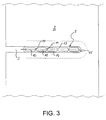
- Each strip 2 is provided with a number of openings or holes 3 which in the embodiment shown have an elongated form, and are open ended to one side so as to firm cut-outs in the strip 2, as shown in Figs 1 and 3.
- a flat tube 4 is inserted in the openings 3 of the cooling pack, the flat tube 4 being bent in a serpentine way and as such is composed of a number of rectilinear sections 5 and bent portions 6.
- the flat tube is preferably of the type obtained by multiple port extrusion, i.e. a flat tube having a number of parallel internal flowing channels 10 (see Fig.
- Such a tube may be produced by a single step extrusion process by using especially adapted extrusion dies.
- the main advantage of such flat tubes is that the heat exchange surface is much greater compared with traditional round tubes, so that heat exchangers based upon this type of tubes are more effective.
- the rectilinear portions are parallel to each other and the distance between the facing outer walls of two adjacent rectilinear portions is equal to the smallest distance between two adjacent openings 3 in the strips 2.
- the heat exchanger of the embodiment shown has parallel rectilinear sections of tubes it is possible, according to the invention, to use non-parallel rectilinear sections.
- the strips are to be provided with openings which are not located on the same place in each strip, but the position of the opening is gradually changing from one strip to another.
- each strip 3 is provided with a number of substantially rectangular openings 24 with four rounded corners 25.
- One dimension of the opening 24 corresponds to the width of the flat tube 4 to be used in connection with this strip 2.
- the other dimension is substantially bigger than the height of the tube 5.
- dimension is substantially equal to the distance between two non-facing walls of two adjacent rectilinear portions of the tube as shown in Fig. 4.
- the heat exchanger is obtained in that the tube is shaped in accordance with Fig. 4.
- the tube 4 is with the bent portion 6 first introduced in the openings 24 of the stack of strips 3. In this way a heat exchanger almost identical to the heat exchanger shown in the figures 1 and 2 can be obtained.
Landscapes
- Engineering & Computer Science (AREA)
- Physics & Mathematics (AREA)
- Thermal Sciences (AREA)
- Mechanical Engineering (AREA)
- General Engineering & Computer Science (AREA)
- Geometry (AREA)
- Heat-Exchange Devices With Radiators And Conduit Assemblies (AREA)
Priority Applications (3)
| Application Number | Priority Date | Filing Date | Title |
|---|---|---|---|
| EP95202797A EP0769669A1 (fr) | 1995-10-17 | 1995-10-17 | Echangeur de chaleur |
| AU72937/96A AU7293796A (en) | 1995-10-17 | 1996-10-16 | Heat exchanger |
| PCT/EP1996/004490 WO1997014927A1 (fr) | 1995-10-17 | 1996-10-16 | Echangeur de chaleur |
Applications Claiming Priority (1)
| Application Number | Priority Date | Filing Date | Title |
|---|---|---|---|
| EP95202797A EP0769669A1 (fr) | 1995-10-17 | 1995-10-17 | Echangeur de chaleur |
Publications (1)
| Publication Number | Publication Date |
|---|---|
| EP0769669A1 true EP0769669A1 (fr) | 1997-04-23 |
Family
ID=8220725
Family Applications (1)
| Application Number | Title | Priority Date | Filing Date |
|---|---|---|---|
| EP95202797A Withdrawn EP0769669A1 (fr) | 1995-10-17 | 1995-10-17 | Echangeur de chaleur |
Country Status (3)
| Country | Link |
|---|---|
| EP (1) | EP0769669A1 (fr) |
| AU (1) | AU7293796A (fr) |
| WO (1) | WO1997014927A1 (fr) |
Cited By (6)
| Publication number | Priority date | Publication date | Assignee | Title |
|---|---|---|---|---|
| WO2000019162A1 (fr) * | 1998-09-30 | 2000-04-06 | Norsk Hydro Asa | Ailette d'echangeur de chaleur |
| DE102006037302A1 (de) * | 2006-08-08 | 2008-02-14 | Behr Gmbh & Co. Kg | Wärmetauscher, insbesondere für eine Kraftfahrzeug-Klimaanlage |
| WO2010003938A1 (fr) * | 2008-07-07 | 2010-01-14 | Arcelik Anonim Sirketi | Evaporateur |
| US20130299152A1 (en) * | 2011-01-21 | 2013-11-14 | Daikin Industries, Ltd. | Heat exchanger and air conditioner |
| US20130299141A1 (en) * | 2011-01-21 | 2013-11-14 | Daikin Industries, Ltd. | Heat exchanger and air conditioner |
| EP3922104A1 (fr) | 2020-06-11 | 2021-12-15 | Calopor | Appareil de réfrigération avec dispositif de retrait de chaleur statique monobloc |
Families Citing this family (1)
| Publication number | Priority date | Publication date | Assignee | Title |
|---|---|---|---|---|
| WO2015040746A1 (fr) * | 2013-09-20 | 2015-03-26 | 三菱電機株式会社 | Échangeur de chaleur ainsi que procédé de fabrication de celui-ci, et dispositif de conditionnement d'air équipé de celui-ci |
Citations (7)
| Publication number | Priority date | Publication date | Assignee | Title |
|---|---|---|---|---|
| US2532301A (en) * | 1945-11-29 | 1950-12-05 | Mccord Corp | Condenser |
| FR1022039A (fr) * | 1950-07-13 | 1953-02-26 | Leon Daum & Cie | Formes d'ailettes pour condenseurs et procédés de mise en place |
| DE2605262A1 (de) * | 1976-02-11 | 1977-08-18 | Benteler Werke Ag | Lamellenwaermetauscher aus durchgehendem metallband |
| US4428419A (en) | 1980-01-28 | 1984-01-31 | Dubrovsky Evgeny V | Tube-and-fin heat exchanger |
| JPS62166294A (ja) * | 1986-01-16 | 1987-07-22 | Nippon Denso Co Ltd | 熱交換器 |
| US4842185A (en) * | 1986-04-25 | 1989-06-27 | Mitsubishi Aluminum Co., Ltd. | Method of brazing a heat exchanger using a reaction flux |
| JPH02154987A (ja) * | 1988-12-06 | 1990-06-14 | Matsushita Refrig Co Ltd | フィン付熱交換器 |
Family Cites Families (1)
| Publication number | Priority date | Publication date | Assignee | Title |
|---|---|---|---|---|
| JPH04177091A (ja) * | 1990-11-08 | 1992-06-24 | Toshiba Corp | 熱交換器 |
-
1995
- 1995-10-17 EP EP95202797A patent/EP0769669A1/fr not_active Withdrawn
-
1996
- 1996-10-16 WO PCT/EP1996/004490 patent/WO1997014927A1/fr active Application Filing
- 1996-10-16 AU AU72937/96A patent/AU7293796A/en not_active Abandoned
Patent Citations (7)
| Publication number | Priority date | Publication date | Assignee | Title |
|---|---|---|---|---|
| US2532301A (en) * | 1945-11-29 | 1950-12-05 | Mccord Corp | Condenser |
| FR1022039A (fr) * | 1950-07-13 | 1953-02-26 | Leon Daum & Cie | Formes d'ailettes pour condenseurs et procédés de mise en place |
| DE2605262A1 (de) * | 1976-02-11 | 1977-08-18 | Benteler Werke Ag | Lamellenwaermetauscher aus durchgehendem metallband |
| US4428419A (en) | 1980-01-28 | 1984-01-31 | Dubrovsky Evgeny V | Tube-and-fin heat exchanger |
| JPS62166294A (ja) * | 1986-01-16 | 1987-07-22 | Nippon Denso Co Ltd | 熱交換器 |
| US4842185A (en) * | 1986-04-25 | 1989-06-27 | Mitsubishi Aluminum Co., Ltd. | Method of brazing a heat exchanger using a reaction flux |
| JPH02154987A (ja) * | 1988-12-06 | 1990-06-14 | Matsushita Refrig Co Ltd | フィン付熱交換器 |
Non-Patent Citations (2)
| Title |
|---|
| PATENT ABSTRACTS OF JAPAN vol. 012, no. 001 (M - 656) 6 January 1988 (1988-01-06) * |
| PATENT ABSTRACTS OF JAPAN vol. 14, no. 404 (M - 1018)<4347> 31 August 1990 (1990-08-31) * |
Cited By (9)
| Publication number | Priority date | Publication date | Assignee | Title |
|---|---|---|---|---|
| WO2000019162A1 (fr) * | 1998-09-30 | 2000-04-06 | Norsk Hydro Asa | Ailette d'echangeur de chaleur |
| DE102006037302A1 (de) * | 2006-08-08 | 2008-02-14 | Behr Gmbh & Co. Kg | Wärmetauscher, insbesondere für eine Kraftfahrzeug-Klimaanlage |
| WO2010003938A1 (fr) * | 2008-07-07 | 2010-01-14 | Arcelik Anonim Sirketi | Evaporateur |
| CN102089602B (zh) * | 2008-07-07 | 2012-12-05 | 阿塞里克股份有限公司 | 蒸发器 |
| US20130299152A1 (en) * | 2011-01-21 | 2013-11-14 | Daikin Industries, Ltd. | Heat exchanger and air conditioner |
| US20130299141A1 (en) * | 2011-01-21 | 2013-11-14 | Daikin Industries, Ltd. | Heat exchanger and air conditioner |
| US9328973B2 (en) | 2011-01-21 | 2016-05-03 | Daikin Industries, Ltd. | Heat exchanger and air conditioner |
| EP3922104A1 (fr) | 2020-06-11 | 2021-12-15 | Calopor | Appareil de réfrigération avec dispositif de retrait de chaleur statique monobloc |
| FR3111417A1 (fr) | 2020-06-11 | 2021-12-17 | Calopor | Appareil de réfrigération avec dispositif de retrait de chaleur statique monobloc |
Also Published As
| Publication number | Publication date |
|---|---|
| AU7293796A (en) | 1997-05-07 |
| WO1997014927A1 (fr) | 1997-04-24 |
Similar Documents
| Publication | Publication Date | Title |
|---|---|---|
| EP0271319B1 (fr) | Procédé de fabrication d'un ensemble échangeur de chaleur avec éléments d'ailettes intégrés | |
| US5036911A (en) | Embossed plate oil cooler | |
| US4815534A (en) | Plate type heat exchanger | |
| US6155340A (en) | Heat exchanger | |
| US5168925A (en) | Heat exchanger | |
| JP3043050B2 (ja) | 熱交換器 | |
| EP0976999B1 (fr) | Echangeur de chaleur | |
| US6070428A (en) | Stack type evaporator | |
| JP2002521644A (ja) | 熱交換器のチューブ・ブロック及びこの目的に使用出来る複室フラット・チューブ | |
| US6892803B2 (en) | High pressure heat exchanger | |
| US7044209B2 (en) | High pressure manifold | |
| JP2002071283A (ja) | 熱交換器 | |
| EP0415584B1 (fr) | Evaporateur de type empilé | |
| KR100826042B1 (ko) | 열 교환기용 편평 튜브의 내측 핀 및 증발기 | |
| US4881311A (en) | Heat exchanger assembly with integral fin unit | |
| EP0769669A1 (fr) | Echangeur de chaleur | |
| EP0448183A2 (fr) | Condenseur | |
| JPH10213382A (ja) | 複合熱交換器 | |
| RU2194926C2 (ru) | Пластинчатый теплообменник с рифлеными пластинами | |
| EP0183211A2 (fr) | Modules d'échange de chaleur et méthode pour leur fabrication | |
| JP2984480B2 (ja) | 積層型熱交換器 | |
| JP2891486B2 (ja) | 熱交換器 | |
| JP2984481B2 (ja) | 積層型熱交換器 | |
| JP2000161888A (ja) | 熱交換器 | |
| JP3108913B2 (ja) | アフタークーラ並設オイルクーラ |
Legal Events
| Date | Code | Title | Description |
|---|---|---|---|
| PUAI | Public reference made under article 153(3) epc to a published international application that has entered the european phase |
Free format text: ORIGINAL CODE: 0009012 |
|
| AK | Designated contracting states |
Kind code of ref document: A1 Designated state(s): DK |
|
| AX | Request for extension of the european patent |
Free format text: SI |
|
| STAA | Information on the status of an ep patent application or granted ep patent |
Free format text: STATUS: THE APPLICATION IS DEEMED TO BE WITHDRAWN |
|
| 18D | Application deemed to be withdrawn |
Effective date: 19971024 |