EP0769586A2 - Verfahren und Vorrichtung zur Verbesserung der Blattbildungsqualität von Papier oder Karton - Google Patents
Verfahren und Vorrichtung zur Verbesserung der Blattbildungsqualität von Papier oder Karton Download PDFInfo
- Publication number
- EP0769586A2 EP0769586A2 EP96103662A EP96103662A EP0769586A2 EP 0769586 A2 EP0769586 A2 EP 0769586A2 EP 96103662 A EP96103662 A EP 96103662A EP 96103662 A EP96103662 A EP 96103662A EP 0769586 A2 EP0769586 A2 EP 0769586A2
- Authority
- EP
- European Patent Office
- Prior art keywords
- jets
- stock
- generating
- nozzle chamber
- recited
- Prior art date
- Legal status (The legal status is an assumption and is not a legal conclusion. Google has not performed a legal analysis and makes no representation as to the accuracy of the status listed.)
- Granted
Links
- 238000000034 method Methods 0.000 title claims abstract description 18
- 239000000835 fiber Substances 0.000 claims abstract description 58
- 230000001737 promoting effect Effects 0.000 claims abstract description 16
- 239000011159 matrix material Substances 0.000 claims description 12
- 238000007599 discharging Methods 0.000 claims description 8
- 230000008878 coupling Effects 0.000 claims description 7
- 238000010168 coupling process Methods 0.000 claims description 7
- 238000005859 coupling reaction Methods 0.000 claims description 7
- 239000012530 fluid Substances 0.000 abstract description 21
- 230000001965 increasing effect Effects 0.000 abstract description 8
- 238000004581 coalescence Methods 0.000 abstract description 3
- 239000000945 filler Substances 0.000 description 6
- 230000015572 biosynthetic process Effects 0.000 description 5
- 239000006185 dispersion Substances 0.000 description 5
- 238000009826 distribution Methods 0.000 description 4
- 230000007246 mechanism Effects 0.000 description 4
- 230000000694 effects Effects 0.000 description 3
- 230000002708 enhancing effect Effects 0.000 description 3
- 239000007788 liquid Substances 0.000 description 3
- 230000004048 modification Effects 0.000 description 3
- 238000012986 modification Methods 0.000 description 3
- 238000004519 manufacturing process Methods 0.000 description 2
- 230000000737 periodic effect Effects 0.000 description 2
- 230000000704 physical effect Effects 0.000 description 2
- 239000013055 pulp slurry Substances 0.000 description 2
- 230000003252 repetitive effect Effects 0.000 description 2
- 230000004075 alteration Effects 0.000 description 1
- 230000001413 cellular effect Effects 0.000 description 1
- 239000000919 ceramic Substances 0.000 description 1
- 230000008859 change Effects 0.000 description 1
- 239000002131 composite material Substances 0.000 description 1
- 230000003247 decreasing effect Effects 0.000 description 1
- 238000013461 design Methods 0.000 description 1
- 238000001035 drying Methods 0.000 description 1
- 238000002474 experimental method Methods 0.000 description 1
- 230000006872 improvement Effects 0.000 description 1
- 238000003780 insertion Methods 0.000 description 1
- 230000037431 insertion Effects 0.000 description 1
- 239000002184 metal Substances 0.000 description 1
- 238000005457 optimization Methods 0.000 description 1
- 239000002245 particle Substances 0.000 description 1
- 239000004033 plastic Substances 0.000 description 1
- 230000003134 recirculating effect Effects 0.000 description 1
- 238000000926 separation method Methods 0.000 description 1
- 238000012546 transfer Methods 0.000 description 1
- XLYOFNOQVPJJNP-UHFFFAOYSA-N water Substances O XLYOFNOQVPJJNP-UHFFFAOYSA-N 0.000 description 1
Images


Classifications
-
- D—TEXTILES; PAPER
- D21—PAPER-MAKING; PRODUCTION OF CELLULOSE
- D21F—PAPER-MAKING MACHINES; METHODS OF PRODUCING PAPER THEREON
- D21F1/00—Wet end of machines for making continuous webs of paper
- D21F1/02—Head boxes of Fourdrinier machines
- D21F1/026—Details of the turbulence section
-
- D—TEXTILES; PAPER
- D21—PAPER-MAKING; PRODUCTION OF CELLULOSE
- D21F—PAPER-MAKING MACHINES; METHODS OF PRODUCING PAPER THEREON
- D21F1/00—Wet end of machines for making continuous webs of paper
- D21F1/02—Head boxes of Fourdrinier machines
-
- D—TEXTILES; PAPER
- D21—PAPER-MAKING; PRODUCTION OF CELLULOSE
- D21F—PAPER-MAKING MACHINES; METHODS OF PRODUCING PAPER THEREON
- D21F1/00—Wet end of machines for making continuous webs of paper
- D21F1/02—Head boxes of Fourdrinier machines
- D21F1/028—Details of the nozzle section
Definitions
- the present invention relates generally to increased productivity and formation quality in paper forming machine headbox components by hydrodynamic optimization of paper and board forming. More particularly, the invention relates to the generation of defined vortices in jets of paper fiber stock enhancing the mixing of the stock as jets of paper fiber stock emanate from a diffuser block for coupling a distributor to a nozzle chamber in a paper forming machine headbox for discharging paper fiber stock upon a wire component promoting uniform flow of the stock from the diffuser block or insert tubes.
- the generation of small scale turbulent flows with the defined vortices of the jets avoids large scale hydrodynamic problems of secondary flows, flow instabilities, boundary-layer separation and other hydrodynamically-induced non-uniformities in the forming section nozzle chamber of the paper forming machine headbox component, avoiding the problems of: twist/warp in board grades; non-uniform basis-weight; non-uniform fiber orientation; non-uniform moisture profile; cockling and diagonal curl in printing paper; and streaking (jagged) dry line on the forming table or wire component.
- the quality of paper and the board forming, in manufacture depends significantly upon the uniformity of the rectangular jet generated by a paper forming machine headbox component for discharging paper fiber stock upon the wire component of the paper forming machine.
- Attempts to establish uniform paper stock flow in the headbox component, particularly the nozzle chamber, and to improve paper fiber orientation at the slice output of the headbox have involved using a diffuser installed between the headbox distributor (inlet) and the headbox nozzle chamber (outlet).
- the diffuser block enhances the supply of a uniform flow of paper stock across the width of the headbox in the machine direction (MD).
- Such a diffuser box typically includes multiple conduits or tubular elements between the distributor and the nozzle chamber which may include step widening or abrupt opening changes to create turbulent flows for defloculation or disintegration of the paper fiber stock to ensure better consistency of the stock.
- High quality typically means good formation, uniform basis weight profiles, uniform sheet structure and high sheet strength properties. These parameters are affected to various degrees by paper fiber distributions, fiber orientations, fiber density and the distributions of fines and fillers. Optimum fiber orientations in the XY plane of the paper and board webs which influences MD/CD elastic stiffness ratios across the width is of significant importance in converting operations and end uses for certain paper grades.
- Conventional paper forming apparatus used primarily in the paper and board industry consists of a unit which is used to transform paper fiber stock, a dilute pulp slurry (i.e., fiber suspended in water at about .5 to 1 percent by weight) into a rectangular jet and to deliver this jet on top of a moving screen (referred to as wire in the paper industry).
- the liquid drains or is sucked under pressure through the screen as it moves forward leaving a mat of web fiber (e.g., about 5 to 7 percent concentration by weight).
- the wet mat of fiber is transferred onto a rotating roll, referred to as a couch roll, transporting the mat into the press section for additional dewatering and drying processes.
- the device which forms the rectangular jet is referred to as a headbox.
- headboxes used in the industry. However, there are some features that are common among all of these devices.
- the pulp slurry (referred to as stock) is transferred through a pipe into a tapered section, the manifold, where the flow is almost uniformly distributed through the width of the box.
- the pipe enters the manifold from the side and therefore, there must be a mechanism to redirect the flow in the machine direction. This is done by a series of circular tubes which are placed in front of the manifold before the converging zone or nozzle chamber of the headbox.
- This section is referred to as the tube bundle, the tube bank or the diffuser block of the headbox.
- These tubes are either aligned on top of each other or are placed in a staggered pattern. There are anywhere from a few hundred to several thousand tubes in a headbox.
- the tubes in current headboxes have a smooth surface starting from a circular shape in the manifold side and going through one or two step changes to larger diameter circular sections. Some tubes converge into a rectangular outlet (some with rounded edges) at the other end opening to the converging zone of the headbox. Analysis relating to the present invention shows that the flow entering the tube may start to recirculate generating vorticity in the machine direction. The sign of the vorticity vector depends on the location of the tube. Very often, there is a pattern that develops as a natural outcome of the tube pattern structure and the structure of the headbox. In current machines, there is no control on the direction or strength of the vortices in the tubes.
- the tubes all have flat smooth internal surface and the flow pattern and secondary flow inside the tubes is governed by the inlet and outlet conditions. The machine direction vorticity could be positive or negative depending on the inlet and outlet conditions which in turn depend on the location of the tube in the tube bank.
- a new concept in accordance with the invention is to control the formation of secondary flow in the tubes in order to achieve a superior flow field inside the converging zone of the headbox.
- Any mechanism used to control or enhance the secondary flow inside the tubes and in the tube bank region to achieve a certain flow property in the converging zone of the headbox is part of this concept.
- the concept relates to the modification of the flow inside the tube bank by altering the internal surface geometry of current tubes or tube inserts.
- the internal surfaces of all of the current tubes or tube inserts are either circular and therefore axisymmetric (type I), or, they start from a circular inlet and eventually converge into a rectangular outlet (type II) with a four fold symmetry (i.e., the entire tube can be divided into symmetric regions by two diagonal cross-sectional planes, one vertical cross-sectional plane and one horizontal cross-sectional plane.
- the new concept is to modify the geometry of the type I and/or inserts such that the internal surface is no longer axisymmetric or non-axisymmetric, and to modify the internal geometry of the type II tubes such that the internal geometry of the tube or the insert is no longer four fold symmetric.
- One described embodiment modifies the internal geometry of each tube in order to generate machine-direction (MD) vorticity and subsequently to arrange the tube or the insert in such a manner so that all the jets in each row of the tube bundle form with the same sign of MD vorticity vector and the jets in each column form with alternating sign of the MD vorticity.
- MD machine-direction
- This generates shear layers which would result in cross-machine orientation of fibers and therefore would increase the strength and other physical properties in the CD while providing effective mixing and turbulent generation between tubes adjacent to each other in each row.
- Another described embodiment modifies the internal geometry of each tube insert or tube in order to generate machine-direction (MD) vorticity and subsequently to arrange the tubes or the inserts in such a manner so that all the jets in each row and column of the tube bundle form with the same sign of MD vorticity vector. This results in strong mixing and dispersion of the fibers and fillers and therefore better uniformity in fiber and filler distribution in the sheet.
- MD machine-direction
- Another mechanism to generate axial vorticity inside the tubes of a headbox is to have a device, a tube insert, wherein a flat section at the manifold side is followed by a converging curved section, followed by a straight tube section, and where, one or more inclined fins or grooves are placed on the flat section or on the flat and the converging curved section of the headbox tube or insert nozzle of the headbox tube.
- the purpose of inclined fins or grooves is to control the defined direction or orientation of the axial vortices generated inside the tubes.
- the converging section of the insert nozzle or tube will accelerate the fluid and increase the angular velocity of the fluid, consequently, increasing the strength of the vortex as the fluid moves toward the straight (constant diameter) section of the tube.
- the present invention relates to methods and apparatus to enhance paper and board forming qualities with insert tubes and/or a diffuser block in the paper forming machine headbox component which generates vorticity in the machine direction (MD) which is superimposed on the streamwise flow to generate a swirling or helical flow through the tubes of the diffuser block.
- Tubes of the diffuser block are designed such that the direction of the swirl or fluid rotation of the paper fiber stock may be controlled and the direction thereof is controlled in such a way to provide effective mixing, coalescence and merging of the jets of fluid emanating from the tubes into the converging section, i.e., nozzle chamber of the headbox.
- Vortex forming means are disclosed for a plurality of tubular elements in the diffuser box for generating controlled axial vortices in the machine direction promoting mixing of the jets of paper stock from the tubular elements as the jets flow into the nozzle chamber to a uniform flow field of stock at the slice opening for the rectangular jet.
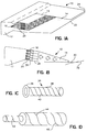
- FIG. 1A illustrates an embodiment of a paper forming machine headbox component 10 for receiving a paper fiber stock and generating a rectangular jet therefrom for discharge upon a wire component moving in a machine direction (MD).
- a distributor 12 is provided for distributing the paper fiber stock flowing into the headbox component 10 in a cross-machine direction (CD) which would be generally perpendicular to the machine direction of the wire component in a conventional hydraulic headbox.
- CD cross-machine direction
- the present invention may also be embodied in a conventional air-cushioned headbox as well as the hydraulic headbox.
- the distributor 12 is provided to supply a flow of paper fiber stock across the width of the headbox 10 in the machine direction.
- a nozzle chamber 14 is shown having an upper surface and a lower surface converging to form a rectangular output lip defining a slice 22 opening for the rectangular jet at opening 24.
- the paper fiber stock flows as indicated by the arrows in the nozzle chamber 14 to output the rectangular jet 30 upon the wire 32 partially shown in FIG. 1B.
- a diffuser block 16 is provided to couple the distributor 12 to the nozzle chamber 14.
- the diffuser block 16 includes a multiplicity of individual tubular elements 18 disposed between the distributor 12 and the nozzle chamber 14, and in accordance with the invention, the presently described embodiment includes vortex forming means 20 provided for a plurality of the tubular elements 18.
- the vortex forming means 20 embodied herein may be provided for a subset or a plurality of the multiple tubular elements 18 for generating controlled axial vortices in the machine direction promoting mixing of the jets of the stock from the tubular elements 18, as the jets flow into the nozzle chamber to a uniform flow field of stock at the slice opening 22 for the rectangular jet 30 from the rectangular opening 24 at the slice 22.
- steps 26 and 28 as might be found in a conventional diffuser block for the purpose of breaking up defloculating or disintegrating the paper fiber stock to enhance the uniformity thereof.
- a step diffuser block is generally provided in conventional headboxes, and the present invention may or may not require the use of such a step diffuser, but for the purpose of the described embodiment, the step diffuser is provided as shown.
- FIG. 1C shows an insert tube 34 which is insertable in a diffuser block for coupling the distributor to the nozzle chamber in a paper forming machine headbox for discharging paper fiber stock upon a wire component moving in a machine direction.
- the diffuser block in conventional machines includes a multiplicity of individual tubular elements as already discussed and also provide for the ability for such inserts, typically smooth cylindrical tubular inserts for varying diameter of the individual tubular elements.
- the inserts of the described embodiment and shown herein are typically used to generate vortices within such tubes and thus, asymmetric or non-axisymmetric surface with ridges or fins or grooves as opposed to smooth axisymmetric inner surfaces are employed.
- the tubular elements and the insert tubes are oriented axially in the machine direction and arranged as a matrix of rows and columns for generating multiple jets of paper fiber stock flowing into the nozzle chamber 14.
- the insert tube 34 includes a flat section inlet 36 for receiving the stock from the distributor, which also serves as a shoulder or rim for securing the insert tube 34 in the diffuser block 16.
- the insert tube 34 embodiment also includes an elongated section outlet 38 connected to the flat section inlet 36 for directing the jets of the paper fiber stock through the tubular elements of the diffuser block 16 as the jets flow towards the nozzle chamber 14.
- vortex forming means 40 are provided for the insert tube 34 for generating the controlled axial vortices in the machine direction to promote mixing of the jets from the elongated section outlet as the jets flow toward the nozzle chamber 14.
- the vortex forming means include an asymmetric interior surface as shown in FIG. 1C within the elongated section outlet 38 for generating the controlled axial vortex therein. More specifically, the asymmetric interior surface has a spiral pitch defining a helical path as shown within the tubular elements to generate the controlled axial vortices as the stock travels along the helical path in the elongated section outlet 38.
- the insert tube 34 may be constructed of plastic, metal, ceramic or composite inserts with the spiral-shaped grooves, fins, ridges or guides of various form at the inner surface.
- One such feature is to form spiral-shaped grooves or patterns through the inner surface of the insert as shown.
- These inserts can be easily placed inside the tubes to generate the desired machine-direction vorticity in the tube.
- the inserts such as tube insert 34 may be placed inside the tubes at the distributor or manifold side of a headbox 10. The initial section of the insert at the inlet may start with a smooth surface before the vortex generating means, discussed above.
- the tubes have the feature of directing the flow in a manner to generate machine direction vorticity in a specific direction (i.e., with a specific vorticity vector sign, defined as positive (+) or negative (-) based on a right-hand rule).
- a specific vorticity vector sign defined as positive (+) or negative (-) based on a right-hand rule.
- the sign of the secondary flow of the vorticity inside the tube is controlled by the spiral-shaped grooves, fins, ridges or guides of various form in the inner surface or such means for generating the vorticity.
- One such feature is to form spiral-shaped grooves or patterns through the inner surfaces of the tubes as shown in FIG. 1D, in a step diffuser box.
- the spiral grooves direct the flow in a recirculating manner generating or increasing the controlled vorticity in the machine direction.
- the grooves have increasing or decreasing pitch depending on the type of tube and the headbox design.
- the pitch of the spiral-shaped grooves may gradually change through the step diffuser tube as indicated by reference numerals 42, 44 and 46; note particularly the increased pitch between the groove 44 and the groove 46.
- the pitch of the grooves depends on the average MD velocity through the tube. If the MD velocity is very large, then the pitch may be considerably smaller than shown in the figure.
- the spiral-shaped grooves, fins or guides allow the fluid to gradually flow in the spiral-shaped pattern of the tube surface.
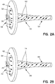
- FIGS. 2A and 2B additional tube insert embodiments are shown including vortex forming means as an inclined fin or groove 56 and 70 on flat section inlets 48 and 62 respectively.
- vortex forming means as an inclined fin or groove 56 and 70 on flat section inlets 48 and 62 respectively.
- Such incline fins or grooves facilitate the generation of the controlled axial vorticity as the stock flows toward the elongated section outlet from the distributor 12 of the headbox 10.
- the mechanism of FIGS. 2A and 2B generate axial vorticity inside the tubes of the headbox wherein the flat section at the manifold or distributor side is followed by a converging curved section, herein curved sections 50 and 64 and converging portions 52 and 66 are provided as portions of the elongated section out let connecting to elongated sections 54 and 68 respectively, in the two embodiments of FIGS.
- the purpose of the inclined fin or groove is to control the direction of the vortex generated inside the tube as shown wherein inlet flow 58 is directed as a vortical flow pattern indicated by reference numeral 60 in FIG. 2A; and incoming flow 72 is directed as vortical flow 74 in the embodiment of FIG. 2B.
- FIG. 2 shows the groove 56 as residing within the elongated outlet portion of the tube as well as on the flat section 48; while FIG. 2B provides the groove or fin 70 as residing solely on the flat surface 62. It should be noted that while a single fin or groove is shown on the tubes more fins may be desirable for creating the axial vorticity within the tubes as well as for ease of placement, orientation independence and the like for fitting such tubes into the diffuser block of conventional headboxes.
- the curved sections 50 and 64 may be incorporated into the elongated section and disposed between the flat section 48 and converging section 52 in FIG. 2A to facilitate the axial vorticity, and as such, provide additional vortex forming means as a curved section included along a portion of the converging section near the flat section for generating the controlled axial vortices as the paper fiber stock flows in the elongated section outlet.
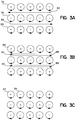
- FIGS. 3A, 3B and 3C illustrate various methods of mixing jets of paper fiber stock emanating from a multiplicity of axially aligned tubes arranged as a matrix of rows and columns in a diffuser block coupled to a nozzle chamber in a paper forming machine headbox for discharging a uniform flow field of stock upon the wire component moving in the machine direction.
- the MD components of vortices of the jets emanating from the tubes are indicated as positive defined or negative defined axial vortices in accordance with the convention of the right-hand rule and where here we use the convention that positive MD points into the surface of the figures. One could also use the convention that MD is the negative direction.
- Positive or negative jets refer to jets with positive or negative MD vorticity, respectively.
- a method in accordance with the invention provides for the generation of positive jets of paper fiber stock emanating from the diffuser block in controlled axial vortices in the machine direction for a first plurality of the tubes, the direction of the vortex being directed in a first positive-defined direction about the axes of each of the first plurality of tubes and positioning at least one of the positive jets adjacent another one of the positive jets promoting mixing as the jets flow into the nozzle chamber. This is illustrated in FIG. 3A where the first row 76 of FIG. 3A and the bottom row 80 of FIG.
- FIG. 3A whereby small scale turbulence is introduced between the individual positively oriented jets of rows 76 and 80 as the fluid flow emanates from the tubes promoting mixing thereof. Small scale turbulence is also introduced between the individual negatively oriented jets of row 78 in FIG. 3A.
- the configuration of FIG. 3A also generates shear layers which would result in cross-machine orientation of fibers and therefore, would increase the strength and other physical properties in the cross-machine direction, as indicated by shear layers in between 82 and 84 with the inner-posed layer of negative defined rows of vorticity as indicated by reference numeral 78.
- the jet orientation of row 78 is provided according to the method by generating negative jets of paper fiber stock emanating from the diffuser block in controlled axial vortices in the machine direction for a second plurality of tubes, the direction of each vortex being directed in a second negative-defined direction about the axes of each of said second plurality of tubes and positioning at least one of the negative jets adjacent another one of the negative jets promoting mixing as the jets flow into the nozzle chamber, herein row 78.
- FIG. 3A illustrates desired flows for enhancing the strength of paper or board because the shear layers in the CD provide CD strength by the alternating MD vorticity direction of the secondary flow of the jets from the tubes in each row of tubes resulting in shear layers which align more fibers in CD.
- FIG. 3B An alternate concept of modifying the internal geometry of each tube in order to generate machine direction vorticity and subsequently arrange the tubes or inserts in a manner such that all the jets of each row and column of the tube bundle form the same sign of MD vorticity vector is shown in FIG. 3B.
- all of the rows and columns have the orientation same indicated by reference numeral 86, namely a positively defined orientation of vorticity which results in turbulent shears as indicated by reference numeral 88 and 90.
- FIG. 3B shows an orientation best for mixing where uniform dispersion is a criteria having emphasis over strength; such as in tissue or light-weight paper applications.
- FIG. 3C illustrates alternating sign vorticity 92 and 94 throughout the rows and columns of the tube bank which provides the configuration of Case 2 discussed below in connection with FIGS. 5A-5H wherein the described counter-rotating pattern of adjacent jets provides better mixing over jets lacking vorticity discussed further below.
- Computer analysis for headboxes employing the configuration of FIG. 3C shows the ability to achieve more uniform flow of the paper fiber stock within the nozzle chamber making secondary jets at the slice weaker and thus noticeable improvement in uniformity.
- FIGS. 3D, 3E and 3F show additional patterns of the tubes for generating vortices of defined orientation, herein the matrix of rows and columns in the diffuser block being either vertical or inclined columns and introducing the vortex patterns in staggered tube arrangements.
- FIGS. 3D, 3E and 3F respectively provide patterns similar to those discussed above in connection with FIGS. 3A, 3B and 3C, wherein the individual secondary vorticity of the jets emanating from the tubes is provided in a staggered pattern in FIGS. 3D-3F.
- the alternating MD vorticity direction of the secondary flow of the jets from the staggered tubes results in shear layers which would align more fibers in the CD.
- FIG. 3D the alternating MD vorticity direction of the secondary flow of the jets from the staggered tubes results in shear layers which would align more fibers in the CD.
- the MD vorticity direction of the secondary flow of the jets from the staggered tubes results in enhanced fiber dispersion and mixing of the fillers in the paper fiber stock.
- the alternating checkerboard MD vorticity direction of the secondary flow of the jets from the staggered tubes results in effective mixing and fiber dispersion.
- FIG. 3G illustrates plural row pairs of common secondary vorticity of the jets from the tubes in a staggered pattern, herein a pair of negatively oriented rows 96 being provided above a pair of positively oriented rows 97 in a repetitive pattern. Accordingly, the alternating MD vorticity direction of the secondary flow of the jets from the staggered tubes in FIG. 3G results in shear layers which would align more fibers in the CD. From the foregoing, it is appreciated to those skilled in the art that the tubes arranged as a matrix of rows and columns in the diffuser block are provided either vertically or inclined and the rows or columns may be provided as staggered for enhancing fiber alignment.
- FIG. 3H similarly shows a repetitive pair vorticity pattern illustrating, e.g., negatively oriented rows 98 and positively oriented rows 99.
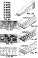
- FIGS. 4A-4H and FIGS. 5A-5H the effect of vorticity in the tubes of the headbox 10 on the flow is illustrated for the slice and the nozzle chamber 14.
- analysis shows the effect of vorticity in the jets leaving the tubes in the tube bank and entering the converging zone of the headbox.
- the purpose of this study is to investigate the effect of vorticity at the tube bank on the free surface rectangular jet 30 at the slice 22. Two cases have been considered, case one with no vorticity and the second case with axial vorticity. These cases are shown in FIGS. 4A and 5A, respectively.
- case #1 (FIGS. 4A-4H) and case #2 (FIGS. 5A-5H) are arranged in vertical columns, as shown in FIGS. 4A and 5A, respectively.
- the flow through the tube in case 1 has velocity component only in the machine direction.
- case 2 the flow in the tube has an axial vorticity imposed on the streamwise flow.
- the imposed secondary flows are counter-rotating axial vortices, that is the direction of rotation is clockwise and counter-clockwise in a checkerboard pattern.
- the cross machine direction, y, and the vertical z, components of the velocity at the tube outlet and the converging zone inlet are given respectively by: and
- Equation (1a, 1b) w and v are the vertical (Z) and transverse (CD) components of velocity, A is the magnitude of the secondary flow at the inlet, ⁇ y and ⁇ z are the horizontal and vertical dimensions of the tube outlet, respectively.
- the magnitude A, of the super-imposed secondary eddy in this study is 1.5% of the average streamwise component.
- the secondary velocity profile at the inlet to the converging zone is defined by a 4th order function of the y and z coordinates.
- the flow is periodic with a wavelength of one-third of the width of the computation domain.
- the vertical component of the flow plays an important role in transferring fluid of high streamwise momentum towards the bottom wall of the headbox. Due to the periodicity of the flow, this momentum transfer varies significantly in the CD direction. Where the vertical velocity towards the wall is larger, the faster moving fluid carried from the middle of the slice to the wall forms a liquid jet. Where the vertical velocity is relatively smaller, a streamwise velocity jet of lower speed appears.
- FIGS. 4D, 4F and 4H where the contour plot of the three velocity components for this case are plotted along a horizontal cross-sectional plane near the lower lip of the slice.
- FIGS. 4G, 4E and 4C show that the flow at the slice has a periodic structure similar to that in Case 1 (i.e., FIGS. 5G, 5E and 5C).
- the deviation of the actual vertical velocity from the average vertical velocity is smaller. Consequently, less fluid with high streamwise momentum is transferred towards the bottom surface of the headbox. Also, less fluid with low streamwise momentum is lifted from the lower surface towards the middle of the slice.
- the secondary jets at the slice for Case 2 are weaker and less noticeable.
- the secondary fluid flow cells created in this case are further away from the bottom and the CD velocity components are smaller than those of the first case.
- the counter-rotating pattern of adjacent jets is perhaps not the most effective pattern for mixing of the fluid and suspended particles in jets from adjacent tubes.
- a more effective method for mixing is to force the jets from the tubes to rotate in the same direction.
- the rotational pattern of the jets should be accordingly controlled using the special tubes outlined above and the specific pattern arrangement of FIGS. 3A, 3B or 3C, as appropriate.
Landscapes
- Paper (AREA)
- Diaphragms For Electromechanical Transducers (AREA)
Applications Claiming Priority (2)
| Application Number | Priority Date | Filing Date | Title |
|---|---|---|---|
| US08/546,548 US5792321A (en) | 1995-10-20 | 1995-10-20 | Methods and apparatus to enhance paper and board forming qualities |
| US546548 | 1995-10-20 |
Publications (3)
| Publication Number | Publication Date |
|---|---|
| EP0769586A2 true EP0769586A2 (de) | 1997-04-23 |
| EP0769586A3 EP0769586A3 (de) | 1998-01-14 |
| EP0769586B1 EP0769586B1 (de) | 2002-10-30 |
Family
ID=24180917
Family Applications (1)
| Application Number | Title | Priority Date | Filing Date |
|---|---|---|---|
| EP96103662A Expired - Lifetime EP0769586B1 (de) | 1995-10-20 | 1996-03-08 | Verfahren und Vorrichtung zur Verbesserung der Blattbildungsqualität von Papier oder Karton |
Country Status (6)
| Country | Link |
|---|---|
| US (2) | US5792321A (de) |
| EP (1) | EP0769586B1 (de) |
| JP (1) | JPH09119087A (de) |
| AT (1) | ATE226987T1 (de) |
| DE (1) | DE69624544T2 (de) |
| PT (1) | PT769586E (de) |
Cited By (4)
| Publication number | Priority date | Publication date | Assignee | Title |
|---|---|---|---|---|
| WO1999057366A3 (de) * | 1998-04-30 | 1999-12-29 | Voith Sulzer Papiertech Patent | Stoffauflauf mit turbulenzkanälen |
| DE19917053A1 (de) * | 1999-04-15 | 2000-11-02 | Deutsch Zentr Luft & Raumfahrt | Verfahren und Vorrichtung zur Herstellung von Papier, wobei eine Fasersuspension als Freistrahl ausgebracht wird |
| EP1403423A1 (de) * | 2002-09-27 | 2004-03-31 | Voith Paper Patent GmbH | Stoffauflauf mit Drallerzeuger |
| US10385996B2 (en) | 2014-09-10 | 2019-08-20 | International Business Machines Corporation | Tapering couplers for connecting fluid flow components |
Families Citing this family (16)
| Publication number | Priority date | Publication date | Assignee | Title |
|---|---|---|---|---|
| US6406595B1 (en) | 1995-10-20 | 2002-06-18 | Institute Of Paper Science And Technology, Inc. | Methods and apparatus to enhance paper and board forming qualities |
| US6425984B2 (en) | 1995-10-20 | 2002-07-30 | Institute Of Paper Science And Technology, Inc. | Layered fiber structure in paper products |
| US6153057A (en) * | 1995-10-20 | 2000-11-28 | Institute Of Paper Science And Technology, Inc. | Methods and apparatus to enhance paper and board forming qualities |
| US6368460B1 (en) | 1995-10-20 | 2002-04-09 | Institute Of Paper Science And Technology, Inc. | Method and apparatus to enhance paper and board forming qualities |
| DE19936330A1 (de) * | 1999-08-02 | 2001-02-08 | Voith Paper Patent Gmbh | Stoffauflauf |
| FI114030B (fi) * | 1999-10-12 | 2004-07-30 | Metso Paper Inc | Menetelmä ja sovitelma paperinvalmistuksen massakomponenttien sekoittamiseksi |
| DE10102198A1 (de) * | 2001-01-18 | 2002-08-22 | Voith Paper Patent Gmbh | Former sowie Stoffauflauf für einen solchen Former |
| DE10140416A1 (de) * | 2001-08-17 | 2003-02-27 | Voith Paper Patent Gmbh | Stoffauflauf |
| US20030145980A1 (en) * | 2002-02-04 | 2003-08-07 | Sinha Sumon Kumar | System and method for using a flexible composite surface for pressure-drop free heat transfer enhancement and flow drag reduction |
| EP1556544A2 (de) * | 2002-11-01 | 2005-07-27 | International Paper Company | Verfahren zur herstellung von mehrschichtigem papier |
| US7401998B2 (en) * | 2004-09-16 | 2008-07-22 | David M. Wahl | Construction of a foamed polymeric manhole chimney |
| US8795473B2 (en) * | 2007-12-11 | 2014-08-05 | Paperchine Inc. | Tube bank apparatus for distributing stock |
| US7955474B2 (en) * | 2007-12-11 | 2011-06-07 | Paperchine Inc. | Tube bank apparatus for distributing stock |
| DE102009045221A1 (de) * | 2009-09-30 | 2011-03-31 | Voith Patent Gmbh | Turbulenzerzeuger für einen Stoffauflauf, Stoffauflauf und Verfahren zur Herstellung des Turbulenzerzeugers |
| CN102154914B (zh) * | 2011-02-24 | 2013-03-20 | 钟洲 | 制备芳纶纸的方法及由该方法获得的芳纶纸 |
| US10876258B2 (en) * | 2018-11-27 | 2020-12-29 | Solenis Technologies, L.P. | Method for improving filler and fiber retention in paper making processes |
Family Cites Families (20)
| Publication number | Priority date | Publication date | Assignee | Title |
|---|---|---|---|---|
| US3846229A (en) * | 1972-01-28 | 1974-11-05 | Lodding Engineering Corp | Flow systems for inducing fine-scale turbulence |
| CH608049A5 (de) * | 1976-01-23 | 1978-12-15 | Escher Wyss Gmbh | |
| US4179222A (en) * | 1978-01-11 | 1979-12-18 | Systematix Controls, Inc. | Flow turbulence generating and mixing device |
| FI66931C (fi) * | 1983-01-04 | 1984-12-10 | Tampella Oy Ab | Haolskiva foer en inloppslaoda foer en pappersmaskin |
| US4604164A (en) * | 1985-01-30 | 1986-08-05 | Mitsubishi Jukogyo Kabushiki Kaisha | Flow restraining elements in the headbox of a paper machine |
| JPH06102879B2 (ja) * | 1985-07-30 | 1994-12-14 | 石川島播磨重工業株式会社 | 抄紙機のヘツドボツクス |
| US4643584A (en) * | 1985-09-11 | 1987-02-17 | Koch Engineering Company, Inc. | Motionless mixer |
| DE3628699A1 (de) * | 1986-08-23 | 1988-03-03 | Voith Gmbh J M | Stoffauflauf |
| DE3715220A1 (de) * | 1987-05-07 | 1988-11-17 | Gruenzweig Hartmann Glasfaser | Fassadenbekleidung |
| SU1490205A1 (ru) * | 1987-11-17 | 1989-06-30 | Хабаровский политехнический институт | Напорный щик бумагоделательной машины |
| US5000227A (en) * | 1988-02-01 | 1991-03-19 | Westvaco Corporation | Pressurized fluid carrier conduit connection |
| US4936689A (en) * | 1988-07-11 | 1990-06-26 | Koflo Corporation | Static material mixing apparatus |
| CA1320860C (en) * | 1988-10-12 | 1993-08-03 | Luc Y. Fortier | Headbox |
| US5019215A (en) * | 1988-10-17 | 1991-05-28 | Groupe Laperrier & Verreault, Inc. | Headbox with conduits having multiply connected domains |
| FI82085C (fi) * | 1989-06-02 | 1991-01-10 | Valmet Paper Machinery Inc | Turbulensgenerator i inloppslaodan av en pappersmaskin. |
| DE4019235A1 (de) * | 1990-06-15 | 1991-12-19 | Voith Gmbh J M | Stoffauflauf |
| US5183537A (en) * | 1991-10-07 | 1993-02-02 | Beloit Technologies, Inc. | Headbox tube bank apparatus and method of directing flow therethrough |
| US5196091A (en) * | 1991-10-29 | 1993-03-23 | Beloit Technologies, Inc. | Headbox apparatus with stock dilution conduits for basis weight control |
| DE9304736U1 (de) * | 1993-03-30 | 1993-05-19 | Sulzer-Escher Wyss GmbH, 7980 Ravensburg | Turbulenzerzeuger für einen Stoffauflauf einer Papiermaschine |
| US5484203A (en) * | 1994-10-07 | 1996-01-16 | Komax Systems Inc. | Mixing device |
-
1995
- 1995-10-20 US US08/546,548 patent/US5792321A/en not_active Expired - Fee Related
-
1996
- 1996-03-08 PT PT96103662T patent/PT769586E/pt unknown
- 1996-03-08 AT AT96103662T patent/ATE226987T1/de not_active IP Right Cessation
- 1996-03-08 DE DE69624544T patent/DE69624544T2/de not_active Expired - Fee Related
- 1996-03-08 EP EP96103662A patent/EP0769586B1/de not_active Expired - Lifetime
- 1996-03-28 JP JP8073480A patent/JPH09119087A/ja active Pending
-
1997
- 1997-08-29 US US08/920,415 patent/US5876564A/en not_active Expired - Fee Related
Cited By (5)
| Publication number | Priority date | Publication date | Assignee | Title |
|---|---|---|---|---|
| WO1999057366A3 (de) * | 1998-04-30 | 1999-12-29 | Voith Sulzer Papiertech Patent | Stoffauflauf mit turbulenzkanälen |
| DE19917053A1 (de) * | 1999-04-15 | 2000-11-02 | Deutsch Zentr Luft & Raumfahrt | Verfahren und Vorrichtung zur Herstellung von Papier, wobei eine Fasersuspension als Freistrahl ausgebracht wird |
| EP1403423A1 (de) * | 2002-09-27 | 2004-03-31 | Voith Paper Patent GmbH | Stoffauflauf mit Drallerzeuger |
| US10385996B2 (en) | 2014-09-10 | 2019-08-20 | International Business Machines Corporation | Tapering couplers for connecting fluid flow components |
| US10422451B2 (en) | 2014-09-10 | 2019-09-24 | International Business Machines Corporation | Tapering couplers for connecting fluid flow components |
Also Published As
| Publication number | Publication date |
|---|---|
| DE69624544T2 (de) | 2003-06-26 |
| DE69624544D1 (de) | 2002-12-05 |
| US5876564A (en) | 1999-03-02 |
| JPH09119087A (ja) | 1997-05-06 |
| EP0769586B1 (de) | 2002-10-30 |
| EP0769586A3 (de) | 1998-01-14 |
| ATE226987T1 (de) | 2002-11-15 |
| US5792321A (en) | 1998-08-11 |
| PT769586E (pt) | 2003-03-31 |
Similar Documents
| Publication | Publication Date | Title |
|---|---|---|
| US5792321A (en) | Methods and apparatus to enhance paper and board forming qualities | |
| US3846229A (en) | Flow systems for inducing fine-scale turbulence | |
| Lundell et al. | Fluid mechanics of papermaking | |
| US3514372A (en) | Headbox method and means for blending of multiple jets | |
| US6425984B2 (en) | Layered fiber structure in paper products | |
| US8303774B2 (en) | Headbox for a machine for producing a fibrous web | |
| US3328236A (en) | Bunched tube approach to a headbox of a papermaking machine | |
| US6153057A (en) | Methods and apparatus to enhance paper and board forming qualities | |
| CA1271354A (en) | Headbox for paper machine | |
| US7067040B2 (en) | Headbox of paper machine or such | |
| US5124002A (en) | Headbox with turbulence generator pipe layers of different cross sections | |
| US3652392A (en) | Contracting pre-slice flow distributor for papermaking machine headbox | |
| US6406595B1 (en) | Methods and apparatus to enhance paper and board forming qualities | |
| US6368460B1 (en) | Method and apparatus to enhance paper and board forming qualities | |
| US7955474B2 (en) | Tube bank apparatus for distributing stock | |
| US6562197B2 (en) | Drainage hydrofoil blade | |
| EP1290273B1 (de) | Stoffauflauf einer papiermaschine | |
| US3092540A (en) | Method and apparatus for distributing particle suspensions | |
| US3471368A (en) | Headbox for papermaking machine | |
| US8075737B2 (en) | Headbox apparatus for a papermaking machine | |
| US3887428A (en) | Manufacture of continuous material webs of fibrous particles at high consistencies by passing particles through a series of constrictions | |
| US9422665B2 (en) | Headbox apparatus | |
| JPH07279079A (ja) | 抄紙機用ヘッドボックス | |
| EP1195463B1 (de) | Stoffauflauf für eine Papiermaschine | |
| US8795473B2 (en) | Tube bank apparatus for distributing stock |
Legal Events
| Date | Code | Title | Description |
|---|---|---|---|
| PUAI | Public reference made under article 153(3) epc to a published international application that has entered the european phase |
Free format text: ORIGINAL CODE: 0009012 |
|
| AK | Designated contracting states |
Kind code of ref document: A2 Designated state(s): AT BE CH DE DK ES FI FR GB GR IE IT LI LU MC NL PT SE |
|
| PUAL | Search report despatched |
Free format text: ORIGINAL CODE: 0009013 |
|
| AK | Designated contracting states |
Kind code of ref document: A3 Designated state(s): AT BE CH DE DK ES FI FR GB GR IE IT LI LU MC NL PT SE |
|
| 17P | Request for examination filed |
Effective date: 19980511 |
|
| 17Q | First examination report despatched |
Effective date: 20000309 |
|
| GRAG | Despatch of communication of intention to grant |
Free format text: ORIGINAL CODE: EPIDOS AGRA |
|
| GRAG | Despatch of communication of intention to grant |
Free format text: ORIGINAL CODE: EPIDOS AGRA |
|
| GRAG | Despatch of communication of intention to grant |
Free format text: ORIGINAL CODE: EPIDOS AGRA |
|
| GRAH | Despatch of communication of intention to grant a patent |
Free format text: ORIGINAL CODE: EPIDOS IGRA |
|
| GRAH | Despatch of communication of intention to grant a patent |
Free format text: ORIGINAL CODE: EPIDOS IGRA |
|
| GRAA | (expected) grant |
Free format text: ORIGINAL CODE: 0009210 |
|
| AK | Designated contracting states |
Kind code of ref document: B1 Designated state(s): AT BE CH DE DK ES FI FR GB GR IE IT LI LU MC NL PT SE |
|
| PG25 | Lapsed in a contracting state [announced via postgrant information from national office to epo] |
Ref country code: NL Free format text: LAPSE BECAUSE OF FAILURE TO SUBMIT A TRANSLATION OF THE DESCRIPTION OR TO PAY THE FEE WITHIN THE PRESCRIBED TIME-LIMIT Effective date: 20021030 Ref country code: LI Free format text: LAPSE BECAUSE OF FAILURE TO SUBMIT A TRANSLATION OF THE DESCRIPTION OR TO PAY THE FEE WITHIN THE PRESCRIBED TIME-LIMIT Effective date: 20021030 Ref country code: GR Free format text: LAPSE BECAUSE OF FAILURE TO SUBMIT A TRANSLATION OF THE DESCRIPTION OR TO PAY THE FEE WITHIN THE PRESCRIBED TIME-LIMIT Effective date: 20021030 Ref country code: CH Free format text: LAPSE BECAUSE OF FAILURE TO SUBMIT A TRANSLATION OF THE DESCRIPTION OR TO PAY THE FEE WITHIN THE PRESCRIBED TIME-LIMIT Effective date: 20021030 Ref country code: BE Free format text: LAPSE BECAUSE OF FAILURE TO SUBMIT A TRANSLATION OF THE DESCRIPTION OR TO PAY THE FEE WITHIN THE PRESCRIBED TIME-LIMIT Effective date: 20021030 |
|
| REF | Corresponds to: |
Ref document number: 226987 Country of ref document: AT Date of ref document: 20021115 Kind code of ref document: T |
|
| REG | Reference to a national code |
Ref country code: GB Ref legal event code: FG4D |
|
| REG | Reference to a national code |
Ref country code: CH Ref legal event code: EP |
|
| REG | Reference to a national code |
Ref country code: IE Ref legal event code: FG4D |
|
| REF | Corresponds to: |
Ref document number: 69624544 Country of ref document: DE Date of ref document: 20021205 |
|
| PG25 | Lapsed in a contracting state [announced via postgrant information from national office to epo] |
Ref country code: DK Free format text: LAPSE BECAUSE OF FAILURE TO SUBMIT A TRANSLATION OF THE DESCRIPTION OR TO PAY THE FEE WITHIN THE PRESCRIBED TIME-LIMIT Effective date: 20030130 |
|
| PG25 | Lapsed in a contracting state [announced via postgrant information from national office to epo] |
Ref country code: LU Free format text: LAPSE BECAUSE OF NON-PAYMENT OF DUE FEES Effective date: 20030308 |
|
| PG25 | Lapsed in a contracting state [announced via postgrant information from national office to epo] |
Ref country code: MC Free format text: LAPSE BECAUSE OF NON-PAYMENT OF DUE FEES Effective date: 20030331 |
|
| REG | Reference to a national code |
Ref country code: PT Ref legal event code: SC4A Free format text: AVAILABILITY OF NATIONAL TRANSLATION Effective date: 20030120 |
|
| NLV1 | Nl: lapsed or annulled due to failure to fulfill the requirements of art. 29p and 29m of the patents act | ||
| PG25 | Lapsed in a contracting state [announced via postgrant information from national office to epo] |
Ref country code: ES Free format text: LAPSE BECAUSE OF FAILURE TO SUBMIT A TRANSLATION OF THE DESCRIPTION OR TO PAY THE FEE WITHIN THE PRESCRIBED TIME-LIMIT Effective date: 20030429 |
|
| REG | Reference to a national code |
Ref country code: CH Ref legal event code: PL |
|
| ET | Fr: translation filed | ||
| PLBE | No opposition filed within time limit |
Free format text: ORIGINAL CODE: 0009261 |
|
| STAA | Information on the status of an ep patent application or granted ep patent |
Free format text: STATUS: NO OPPOSITION FILED WITHIN TIME LIMIT |
|
| 26N | No opposition filed |
Effective date: 20030731 |
|
| PGFP | Annual fee paid to national office [announced via postgrant information from national office to epo] |
Ref country code: PT Payment date: 20040309 Year of fee payment: 9 Ref country code: GB Payment date: 20040309 Year of fee payment: 9 |
|
| PGFP | Annual fee paid to national office [announced via postgrant information from national office to epo] |
Ref country code: IE Payment date: 20040315 Year of fee payment: 9 |
|
| PGFP | Annual fee paid to national office [announced via postgrant information from national office to epo] |
Ref country code: FR Payment date: 20040318 Year of fee payment: 9 |
|
| PGFP | Annual fee paid to national office [announced via postgrant information from national office to epo] |
Ref country code: SE Payment date: 20040326 Year of fee payment: 9 |
|
| PG25 | Lapsed in a contracting state [announced via postgrant information from national office to epo] |
Ref country code: IE Free format text: LAPSE BECAUSE OF NON-PAYMENT OF DUE FEES Effective date: 20050308 Ref country code: GB Free format text: LAPSE BECAUSE OF NON-PAYMENT OF DUE FEES Effective date: 20050308 |
|
| PG25 | Lapsed in a contracting state [announced via postgrant information from national office to epo] |
Ref country code: SE Free format text: LAPSE BECAUSE OF NON-PAYMENT OF DUE FEES Effective date: 20050309 |
|
| PGFP | Annual fee paid to national office [announced via postgrant information from national office to epo] |
Ref country code: DE Payment date: 20050526 Year of fee payment: 10 |
|
| PGFP | Annual fee paid to national office [announced via postgrant information from national office to epo] |
Ref country code: FI Payment date: 20050527 Year of fee payment: 10 Ref country code: AT Payment date: 20050527 Year of fee payment: 10 |
|
| PG25 | Lapsed in a contracting state [announced via postgrant information from national office to epo] |
Ref country code: PT Free format text: LAPSE BECAUSE OF NON-PAYMENT OF DUE FEES Effective date: 20050908 |
|
| REG | Reference to a national code |
Ref country code: PT Ref legal event code: MM4A Effective date: 20050908 |
|
| EUG | Se: european patent has lapsed | ||
| GBPC | Gb: european patent ceased through non-payment of renewal fee |
Effective date: 20050308 |
|
| PG25 | Lapsed in a contracting state [announced via postgrant information from national office to epo] |
Ref country code: FR Free format text: LAPSE BECAUSE OF NON-PAYMENT OF DUE FEES Effective date: 20051130 |
|
| REG | Reference to a national code |
Ref country code: IE Ref legal event code: MM4A |
|
| REG | Reference to a national code |
Ref country code: FR Ref legal event code: ST Effective date: 20051130 |
|
| PG25 | Lapsed in a contracting state [announced via postgrant information from national office to epo] |
Ref country code: FI Free format text: LAPSE BECAUSE OF NON-PAYMENT OF DUE FEES Effective date: 20060308 Ref country code: AT Free format text: LAPSE BECAUSE OF NON-PAYMENT OF DUE FEES Effective date: 20060308 |
|
| PGFP | Annual fee paid to national office [announced via postgrant information from national office to epo] |
Ref country code: IT Payment date: 20060331 Year of fee payment: 11 |
|
| PG25 | Lapsed in a contracting state [announced via postgrant information from national office to epo] |
Ref country code: DE Free format text: LAPSE BECAUSE OF NON-PAYMENT OF DUE FEES Effective date: 20061003 |
|
| PG25 | Lapsed in a contracting state [announced via postgrant information from national office to epo] |
Ref country code: IT Free format text: LAPSE BECAUSE OF NON-PAYMENT OF DUE FEES Effective date: 20070308 |